Page is loading ...

STEREO-DJ-MISCHPULT
STEREO DJ MIXER
TABLE DE MIXAGE DJ STEREO
MIXER DJ STEREO
MPX-44 Best.-Nr. 20.2060
BEDIENUNGSANLEITUNG • INSTRUCTION MANUAL • MODE D’EMPLOI • ISTRUZIONI PER L’USO
GEBRUIKSAANWIJZING • MANUAL DE INSTRUCCIONES • INSTRUKCJA OBSŁUGI
SIKKERHEDSOPLYSNINGER • SÄKERHETSFÖRESKRIFTER • TURVALLISUUDESTA

2
Bevor Sie einschalten ...
Wir wünschen Ihnen viel Spaß mit Ihrem neuen Gerät von
„img Stage Line“. Dabei soll Ihnen diese Bedienungsan-
leitung helfen, alle Funktionsmöglichkeiten kennen zu ler-
nen. Die Beachtung der Anleitung vermeidet außerdem
Fehlbedienungen und schützt Sie und Ihr Gerät vor even-
tuellen Schäden durch unsachgemäßen Gebrauch.
Den deutschen Text finden Sie auf den Seiten 4–7.
Before you switch on ...
We wish you much pleasure with your new “img Stage
Line” unit. With these operating instructions you will be
able to get to know all functions of the unit. By following
these instructions false operations will be avoided, and
possible damage to yourself and your unit due to im-
proper use will be prevented.
You will find the English text on the pages 4–7.
D
A
CH
GB
Przed uruchomieniem ...
Życzymy zadowolenia z nowego produktu “img Stage
Line”. Dzięki tej instrukcji obsługi będą Państwo w
stanie poznać wszystkie funkcje tego urządzenia.
Stosując się do instrukcji unikną Państwo błędów i
ewentualnego uszkodzenia urządzenia na skutek nie-
prawidłowego użytkowania.
Tekst polski znajduje się na stronach 16– 17.
Voordat u inschakelt ...
Wij wensen u veel plezier met uw nieuw toestel van “img
Stage Line”. Met behulp van bijgaande gebruiksaan-
wijzing zal u alle functiemogelijkheden leren kennen.
Door deze instructies op te volgen zal een slechte wer-
king vermeden worden, en zal een eventueel letsel aan
uzelf en schade aan uw toestel tengevolge van onzorg-
vuldig gebruik worden voorkomen.
U vindt de nederlandstalige tekst op de pagina’s 12–15.
PL
B
NL Antes de cualquier instalación
Tenemos de agradecerle el haber adquirido un equipo
“img Stage Line” y le deseamos un agradable uso. Este
manual quiere ayudarle a conocer las multiples facetas
de este equipo y evitar cualquier uso inadecuado. La
observación de las instrucciones evita operaciones erró-
neas y protege Vd. y vuestro aparato contra todo daño
posible por cualquier uso inadecuado.
La versión española se encuentra en las páginas
12–15.
Inden De tænder for apparatet ...
Vi ønsker Dem god fornøjelse med Deres nye “img
Stage Line” apparat. Læs oplysningerne for en sikker
brug af apparatet før ibrugtagning. Følg sikkerhedsop-
lysningerne for at undgå forkert betjening og for at be-
skytte Dem og Deres apparat mod skade på grund af for-
kert brug.
Sikkerhedsoplysningerne finder De på side 18.
E
DK
Förskrift
Vi önskar dig mycket nöje med din nya enhet från “img
Stage Line”. Läs gärna säkerhetsinstruktionerna innan
du använder enheten. Genom att följa säkerhetsinstruk-
tionerna kan många problem undvikas, vilket annars kan
skada enheten.
Du finner säkerhetsinstruktionerna på sidan 18.
SFIN
Avant toute mise en service ...
Nous vous remercions d’avoir choisi un appareil “img
Stage Line” et vous souhaitons beaucoup de plaisir à
l’utiliser. Cette notice a pour objectif de vous aider à
mieux connaître les multiples facettes de l’appareil. En
outre, en respectant les conseils donnés, vous éviterez
toute mauvaise manipulation de sorte que vous-même et
votre appareil soient protégés de tout dommage.
La version française se trouve pages 8–11.
Prima di accendere ...
Vi auguriamo buon divertimento con il Vostro nuovo
apparecchio “img Stage Line”. Le istruzioni per l’uso Vi
possono aiutare a conoscere tutte le possibili funzioni. E
rispettando quanto spiegato nelle istruzioni, evitate di
commettere degli errori, e così proteggete Voi stessi, ma
anche l’apparecchio, da eventuali rischi per uso impro-
prio.
Il testo italiano lo potete trovare alle pagine 8–11.
F
B
CH
I
Ennen virran kytkemistä ...
Toivomme, että uusi “img Stage Line”-laitteesi tuo sinulle
paljon iloa ja hyötyä. Ole hyvä ja lue käyttöohjeet ennen
laitteen käyttöönottoa. Luettuasi käyttöohjeet voit käyt-
tää laitetta turvallisesti ja vältyt laitteen väärinkäytöltä.
Käyttöohjeet löydät sivulta 18.
wwwwww..iimmggssttaaggeelliinnee..ccoomm

3
2
13
4
0
2
13
4
0
+9
+6
+3
0
–3
–5
–7
–10
–15
–20
5
10
BOOTH
0
5
10
ZONE
0
5
BAL
LR
5
POWER
LAMP
12V/5W
+9
+6
+3
0
–3
–5
–7
–10
–15
–20
PFL
PHONO / LINE
MAX
GAIN
MIN
MID
HIGH
0
0
+15
+15
+9
+6
+3
0
–3
–5
–7
–10
–15
–20
PHONO / LINE
MAX
GAIN
MIN
MID
HIGH
0
0
+15
+15
+9
+6
+3
0
–3
–5
–7
–10
–15
–20
CD / LINE
MAX
GAIN
MIN
MID
HIGH
0
0
+15
+15
+9
+6
+3
0
–3
–5
–7
–10
–15
–20
LINE / LINE
MAX
GAIN
MIN
MID
HIGH
0
0
+15
+15
+9
+6
+3
0
–3
–5
–7
–10
–15
–20
LEVEL
–30
–30
–30
–30
–30
–30
–30
–30
CUT
CUT
CUT
CUT
CUT
CUT
CUT
CUT
LOW LOWLOWLOW
4-CHANNEL PRO SOUND MIXER
0 0 00
CUT –30 +15 +15
–30 +15+15
–30 CUT CUT –30CUT
PFL PFL PFL PFL
MPX-44
C
C.F. ASSIGN B
CROSSFADER
100
PGM
MASTER
100
PHONES
MIX
C.F. ASSIGN A
GAIN
MAXMIN
100
5
PAD PAD
DJ MIC MIC1
HIGH
MID
0
–12+12
LOW
LEVEL
0
–12+12
GAIN
MAXMIN
100
5
0
–12+12
LEVEL
0
–12+12
0
–12+12
AUTO
TALK
MIC
ON MIC
ON PFL
0
–12+12
HIGH
MID
LOW
➀
➁
RECZONEBOOTHMASTER
LEFTRIGHT
BALANCED
1 – GND
2 – HOT
3 – COLD
LEFT
RIGHT
DJ MICMIC 1
CH 1CH 2CH 3CH 4 PHLINEPHLINECDLINELINELINE
230 V~ / 50 Hz
GND GND
123 4 5 6 7 8
14 15 16 17 18 19 20 21 22 23 24 25 26 27
12
13
10
11
30 31 32 33 34 35 36
9
28 29

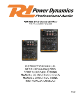
Bitte klappen Sie die Seite 3 heraus. Sie sehen
dann immer die beschriebenen Bedienelemente
und Anschlüsse.
1 Übersicht der Bedienelemente und
Anschlüsse
1.1 Frontseite
1Gain-Regler für die Eingangsverstärkung der
Stereo-Kanäle 1–4
2Eingangsumschalter für die Stereo-Kanäle 1–4
3LED-Pegelanzeigen für die Stereo-Kanäle 1–4:
Anzeige des Pre-Fader-Signalpegels, d.h. des
Signalpegels vor dem jeweiligen Kanalfader (4)
4Pegelregler (Fader) für die Stereo-Kanäle 1–4
5Balanceregler für das Ausgangssignal der Buch-
sen MASTER (30), BOOTH (31) und ZONE (32)
6Stereo-LED-Pegelanzeige für das Ausgangs-
signal der Buchsen MASTER (30)
7BNC-Buchse zum Anschluss einer Schwanen-
halsleuchte (12V/5W max.)
8Ein-/Ausschalter des Mischpults, mit darüber lie-
gender Betriebsanzeige
9Eingangsbuchsen (sym.) für den DJ-Mikrofon-
kanal DJ MIC und den zweiten Mikrofonkanal
MIC 1; der Mikrofonanschluss ist über XLR- oder
6,3-mm-Klinkenstecker möglich
[Alternativ können auch die jeweiligen Mikrofon-
eingänge (36) auf der Rückseite genutzt werden.]
10 PAD-Schalter für die Mikrofonkanäle: bei nach
unten geschobenem Schalter wird der Eingangs-
pegel des jeweiligen Mikrofons um 15dB abge-
senkt
11 Gain-Regler für die Eingangsverstärkung der
Mikrofonkanäle
12 3fache Klangregelung (max. ±12dB) für die Mi-
krofonkanäle:
HIGH = Höhen, MID = Mitten, LOW = Bässe
13 Pegelregler für die zwei Mikrofonkanäle
14 Ein-/Ausschalttasten für die Mikrofonkanäle; bei
gedrückter Taste (LED darüber leuchtet) ist das
jeweilige Mikrofon eingeschaltet
15 Talkover-Taste für den DJ-Mikrofonkanal: bei ge-
drückter Taste (LED darüber leuchtet) werden
bei Durchsagen über das DJ-Mikrofon die Ka-
näle 1–4 automatisch um 16dB abgesenkt
16 PFL-Taste zum Vorhören des Mikrofonkanals
MIC 1 über einen Kopfhörer an der Buchse
(27); bei gedrückter Taste (PFL-Funktion für den
Kanal eingeschaltet) leuchtet die darüber lie-
gende LED
17 3fache Klangregelung (max. +15dB,
-
30dB) für
die Stereo-Kanäle 1–4:
HIGH = Höhen, MID = Mitten, LOW = Bässe
18 Zuordnungsschalter für die Überblendfunktion:
Auswahl des Kanals, der eingeblendet wird, wenn
der Crossfader (19) nach links gezogen wird
19 Crossfader zum Überblenden zwischen zwei der
Stereo-Kanäle 1–4; die Kanäle werden mit den
C. F. ASSIGN-Schaltern (18 und 20) ausgewählt
(Wird die Überblendfunktion nicht benötigt, beide
Schalter auf „0“ stellen.)
20 Zuordnungsschalter für die Überblendfunktion:
Auswahl des Kanals, der eingeblendet wird, wenn
der Crossfader (19) nach rechts gezogen wird
21 PFL-Tasten zum Vorhören der Stereo-Kanäle
1–4 über einen Kopfhörer an der Buchse
(27); bei gedrückter Taste (PFL-Funktion für den
jeweiligen Kanal eingeschaltet) leuchtet die dar-
über liegende LED
22 Lautstärkeregler für den Kopfhörerausgang
(27)
23 Überblendregler PHONES zur Auswahl des Ab-
hörsignals für den Kopfhörerausgang (27):
Fader ganz links („PFL“)
Vorhören („Pre Fader Listening“) der Kanäle,
deren Taste PFL (16 bzw. 21) gedrückt ist
Fader ganz rechts („PGM“)
Abhören des laufenden Musikprogramms vor
den Ausgangsreglern (24, 25, 26)
24 Pegelregler für den Ausgang ZONE (32)
25 Pegelregler für die MASTER-Ausgänge (30)
26 Pegelregler für den Ausgang BOOTH (31)
27 6,3-mm-Klinkenbuchse zum Anschluss eines
Stereo-Kopfhörers (Impedanz min. 8Ω)
1.2 Rückseite
28 Netzkabel zum Anschluss an eine Netzsteck-
dose 230V~/50Hz
29 Masse-Klemmschrauben für angeschlossene
Plattenspieler
30 Stereo-Ausgänge MASTER – wahlweise XLR
(sym.) oder Cinch – für den Anschluss des Haupt-
verstärkers
31 Stereo-Ausgang BOOTH (Cinch) für den An-
schluss eines weiteren Verstärkers, z.B. für die
Monitoranlage
32 Stereo-Ausgang ZONE (Cinch) für den An-
schluss eines weiteren Verstärkers, z.B. für die
Nebenraum-Beschallung
33 Stereo-Aufnahmeausgang (Cinch) für den An-
schluss eines Tonaufnahmegerätes; der Aufnah-
mepegel ist unabhängig von der Stellung der
Ausgangsregler (24, 25, 26)
34 Stereo-Eingänge LINE und CD (Cinch) für die
Kanäle 1–4 zum Anschluss von Geräten mit
Line-Pegel-Ausgängen (z.B. MD-Recorder, CD-
Spieler)
35 Stereo-Eingänge PH (Cinch) für die Kanäle
1 und 2 zum Anschluss von Plattenspielern mit
Magnetsystem
36 Eingangsbuchsen (6,3-mm-Klinke, sym.) für den
DJ-Mikrofonkanal DJ MIC und den zweiten Mikro-
fonkanal MIC 1; alternativ zu den jeweiligen Mi-
krofoneingängen (9) auf der Frontseite
Please unfold page 3. Then you can always see the
operating elements and connections described.
1 Operating Elements and Connections
1.1 Front panel
1Gain controls for the input amplification of the
stereo channels 1 to 4
2Input selector switches for the stereo channels 1
to 4
3LED level indications for the stereo channels 1 to
4: display of the prefader signal level, i.e. of the
signal level ahead of the corresponding channel
fader (4)
4Level controls (faders) for the stereo channels 1
to 4
5Balance control for the output signal at the jacks
MASTER (30), BOOTH (31), and ZONE (32)
6Stereo LED level indication for the output signal
of the jacks MASTER (30)
7BNC jack for connecting a gooseneck light
(12V/5W max.)
8Power switch of the mixer with power LED above
it
9Input jacks (bal.) for the DJ microphone channel
DJ MIC and the second microphone channel
MIC 1; connection of a microphone is possible
via XLR plug or 6.3mm plug
[As an alternative, the corresponding micro-
phone inputs (36) on the rear panel of the unit
may be used.]
10 PAD switches for the microphone channels: with
the switch in the lower position, the input level of
the corresponding microphone is attenuated by
15dB
11 Gain controls for the input amplification of the
microphone channels
12 3-way tone control (±12dB max.) for the micro-
phone channels: HIGH, MID, LOW
13 Level controls for the two microphone channels
14 On-off switches for the microphone channels;
with the button pressed (LED above it lights up),
the corresponding microphone is switched on
15 Talkover switch for the DJ microphone channel:
with the button pressed (LED above it lights up),
the channels 1 to 4 are automatically attenuated
by 16dB when announcements are made via the
DJ microphone
16 PFL button for prefader listening to the micro-
phone channel MIC 1 via headphones connect-
ed to the jack (27); with the button pressed
(PFLfunction activated for the channel), the LED
above the button lights up
17 3-way equalizer (+15dB,
-
30dB max.) for the
stereo channels 1 to 4:
HIGH, MID, LOW
18 Assignment switch for crossfading: selection of
the channel to be faded in with the crossfader
(19) moved to the left
19 Crossfader for crossfading between two of the
stereo channels 1 to 4; the channels are select-
ed with the C. F. ASSIGN switches (18 and 20).
[If crossfading is not required, set both switches
to “0”.]
20 Assignment switch for crossfading: selection of
the channel to be faded in with the crossfader
(19) moved to the right
21 PFL buttons for prefader listening to the stereo
channels 1 to 4 via headphones connected to the
jack (27); with the button pressed (PFL func-
tion activated for the corresponding channel), the
LED above the button lights up
22 Volume control for the headphone output (27)
23 Crossfading control PHONES for selecting the
monitoring signal for the headphone output
(27)
fader at the left stop (“PFL”)
prefader listening to the channels of which the
button PFL (16 or 21) has been pressed
fader at the right stop (“PGM”)
monitoring of the current music programme
ahead of the output controls (24, 25, 26)
24 Level control for the output ZONE (32)
25 Level control for the MASTER outputs (30)
26 Level control for the output BOOTH (31)
27 6.3mm jack for connecting stereo headphones
(minimum impedance 8Ω)
1.2 Rear panel
28 Mains cable for connecting the unit to a mains
socket 230V~/50Hz
29 Ground clamping screws for turntables connected
30 Stereo outputs MASTER [optionally XLR jacks
(bal.) or phono jacks] for connecting the main
amplifier
31 Stereo output BOOTH (phono jacks) for connect-
ing another amplifier, e.g. for the monitoring
system
32 Stereo output ZONE (phono jacks) for connect-
ing another amplifier, e.g. for PA application in
adjoining rooms
33 Stereo recording output (phono jacks) for con-
necting an audio recorder; the recording level is
independent of the position of the output controls
(24, 25, 26)
34 Stereo inputs LINE and CD (phono jacks) for the
channels 1 to 4 for connecting units with line
level outputs (e.g. MD recorder, CD player)
35 Stereo inputs PH (phono jacks) for the channels
1 and 2 for connecting turntables with magnetic
system
36 Input jacks (6.3mm jacks, bal.) for the DJ micro-
phone channel DJ MIC and the second micro-
phone channel MIC 1; as an alternative to the
corresponding microphone inputs (9) on the front
panel
4
GB
D
A
CH

2 Hinweise für den sicheren Gebrauch
Dieses Gerät entspricht der Richtlinie für elektro-
magnetische Verträglichkeit 89/336/EWG und der
Niederspannungsrichtlinie 73/23/EWG.
Beachten Sie auch unbedingt die folgenden Punkte:
●Das Gerät ist nur zur Verwendung im Innenbe-
reich geeignet. Schützen Sie es vor Tropf- und
Spritzwasser, hoher Luftfeuchtigkeit und Hitze
(zulässiger Einsatztemperaturbereich 0–40°C).
●Stellen Sie keine mit Flüssigkeit gefüllten Gefäße,
z.B. Trinkgläser, auf das Gerät.
●Nehmen Sie das Gerät nicht in Betrieb bzw. ziehen
Sie sofort den Netzstecker aus der Steckdose:
1. wenn sichtbare Schäden am Gerät oder an der
Netzanschlussleitung vorhanden sind,
2. wenn nach einem Sturz oder Ähnlichem der
Verdacht auf einen Defekt besteht,
3. wenn Funktionsstörungen auftreten.
Lassen Sie das Gerät in jedem Fall in einer Fach-
werkstatt reparieren.
●Eine beschädigte Netzanschlussleitung darf nur
durch den Hersteller oder durch eine autorisierte
Fachwerkstatt ersetzt werden.
●Ziehen Sie den Netzstecker nie am Kabel aus der
Steckdose, fassen Sie immer am Stecker an.
●Verwenden Sie für die Reinigung nur ein trocke-
nes, weiches Tuch, niemals Wasser oder Chemi-
kalien.
●Wird das Gerät zweckentfremdet, nicht richtig an-
geschlossen, falsch bedient oder nicht fachge-
recht repariert, kann keine Haftung für daraus
resultierende Sach- oder Personenschäden und
keine Garantie für das Gerät übernommen wer-
den.
●Soll das Gerät endgültig aus dem Betrieb genom-
men werden, übergeben Sie es zur umweltge-
rechten Entsorgung einem örtlichen Recycling-
betrieb.
3 Einsatzmöglichkeiten
Das Mischpult MPX-44 ist für beliebige DJ-Anwen-
dungen im privaten oder professionellen Bereich
geeignet. Es lassen sich bis zu sechs Geräte mit
Line-Pegel (z.B. CD-Spieler), bis zu zwei Platten-
spieler und zwei Mikrofone anschließen.
Das Mischpult ist für die Montage in ein Rack für
Geräte mit einer Breite von 482mm (19") vorgese-
hen. Für den Einbau werden 4 HE (Höheneinheiten)
= 177mm benötigt. Es kann jedoch auch frei aufge-
stellt werden.
4 Geräte anschließen
Vor dem Anschließen von Geräten bzw. Ändern be-
stehender Anschlüsse das Mischpult ausschalten.
1) Die Stereo-Tonquellen an die entsprechenden
Cinch-Eingangsbuchsen der Kanäle 1–4 an-
schließen (weiße Buchse LEFT = linker Kanal;
rote Buchse RIGHT = rechter Kanal):
–Geräte mit Line-Pegel-Ausgang (z.B. MD-Re-
corder, CD-Spieler, Kassettenrecorder) an die
Buchsen LINE oder CD (34);
–Plattenspieler mit Magnetsystem an die Buch-
sen PH (35). Die Masseanschlüsse der Plat-
tenspieler mit den Klemmschrauben GND (29)
verbinden.
2) Es lassen sich zwei Mikrofone anschließen: ein
DJ-Mikrofon an den DJ-Mikrofonkanal DJ MIC
und ein weiteres Mikrofon an den zweiten Mikro-
fonkanal MIC 1. Das jeweilige Mikrofon entweder
über einen XLR- oder einen 6,3-mm-Klinkenste-
cker an den Mikrofoneingang (9) auf der Front-
platte anschließen oder über einen 6,3-mm-Klin-
kenstecker an den entsprechenden Mikrofonein-
gang (36) auf der Rückseite.
3) Zum Anschluss von Verstärkern stehen mehrere
Stereo-Ausgänge mit eigenen Pegelreglern zur
Verfügung:
–die Ausgänge MASTER (30); hier sollte der
Hauptverstärker für die Saalbeschallung ange-
schlossen werden, wahlweise an den symme-
trischen XLR- oder an den Cinch-Ausgang
–der Ausgang BOOTH (31); hier kann z.B. der
Verstärker für eine Monitoranlage angeschlos-
sen werden
–der Ausgang ZONE (32); hier kann z.B. ein
zusätzlicher Verstärker für eine Nebenraum-
Beschallung angeschlossen werden
4) Sollen Tonaufnahmen gemacht werden, das Auf-
nahmegerät an den Stereo-Ausgang REC (33)
anschließen. Der Aufnahmepegel ist unabhängig
von der Stellung der drei Ausgangsregler ZONE,
MASTER und BOOTH (24, 25, 26).
5) An die 6,3-mm-Klinkenbuchse (27) kann ein
Stereo-Kopfhörer (Impedanz min. 8Ω) ange-
schlossen werden, zum Vorhören der Eingangs-
kanäle oder zum Abhören des laufenden Musik-
programms vor den drei Ausgangsreglern ZONE,
MASTER und BOOTH (24, 25, 26).
6) Zur Pultbeleuchtung kann eine Schwanenhals-
leuchte (12V/5W max.) an die BNC-Buchse
LAMP (7) angeschlossen werden, z.B. die Leuch-
te GNL-205 aus dem Programm von „img Stage
Line“. Die Leuchte wird mit dem Mischpult ein-
und ausgeschaltet.
7) Zuletzt den Stecker des Netzkabels (28) in eine
Steckdose (230V~/50Hz) stecken.
Achtung! Das Gerät wird mit lebensgefährlicher
Netzspannung (230V~) versorgt. Nehmen Sie
deshalb nie selbst Eingriffe im Gerät vor. Durch un-
sachgemäßes Vorgehen besteht die Gefahr eines
elektrischen Schlages. Außerdem erlischt beim
Öffnen des Gerätes jeglicher Garantieanspruch.
2 Safety Notes
This unit corresponds to the directive for electro-
magnetic compatibility 89/336/EEC and to the low
voltage directive 73/23/EEC.
Please observe the following items in any case:
●The unit is suitable for indoor use only. Protect it
against dripping water and splash water, high air
humidity, and heat (admissible ambient tempera-
ture range 0–40°C).
●Do not place any vessel filled with liquid on the
unit, e.g. a drinking glass.
●Do not operate the unit or immediately disconnect
the plug from the mains socket
1. if there is visible damage to the unit or to the
mains cable,
2. if a defect might have occurred after the unit
was dropped or suffered a similar accident,
3. if malfunctions occur.
In any case the unit must be repaired by skilled
personnel.
●A damaged mains cable must be replaced by the
manufacturer or authorized, skilled personnel only.
●Never pull the mains cable for disconnecting the
mains plug from the socket, always seize the plug.
●For cleaning only use a dry, soft cloth; never use
chemicals or water.
●No guarantee claims for the unit and no liability for
any resulting personal damage or material
damage will be accepted if the unit is used for
other purposes than originally intended, if it is not
correctly connected, operated or not repaired in
an expert way.
●If the unit is to be put out of operation definitively,
take it to a local recycling plant for a disposal
which is not harmful to the environment.
●Important for U.K. Customers!
The wires in this mains lead are coloured in
accordance with the following code:
blue = neutral
brown = live
As the colours of the wires in the mains lead of this
appliance may not correspond with the coloured
markings identifying the terminals in your plug,
proceed as follows:
1. The wire which is coloured blue must be con-
nected to the terminal in the plug which is
marked with the letter Nor coloured black.
2. The wire which is coloured brown must be con-
nected to the terminal which is marked with the
letter Lor coloured red.
3 Applications
The mixer MPX-44 is suitable for any private or pro-
fessional DJ applications. It allows connection of up
to six units with line level (e.g. CD player), up to two
turntables, and two microphones.
The mixer is designed for installation into a rack
for units of a width of 482mm (19"). For rack instal-
lation, 4 RS (rack spaces) = 177mm are required.
However, the mixer can also be placed as desired.
4 Connection
Switch off the mixer prior to connecting any units or
to changing any existing connections.
1) Connect the stereo audio sources to the corre-
sponding phono input jacks of the channels 1 to 4
(white jack LEFT; red jack RIGHT):
– units with line level output (e.g. MD recorder,
CD player, cassette recorder) to the jacks
LINE or CD (34);
– turntables with magnetic system to the jacks
PH (35). Connect the ground connections of the
turntables to the clamping screws GND (29).
2) Connection of two microphones is possible:
Connect a DJ microphone to the DJ microphone
channel DJ MIC and another microphone to the
second microphone channel MIC 1. Either
connect the corresponding microphone via an
XLR plug or a 6.3mm plug to the microphone
input (9) on the front panel or via a 6.3mm plug to
the corresponding microphone input (36) on the
rear panel.
3) For connecting amplifiers, several stereo outputs
with individual level controls are available:
– outputs MASTER (30): it is recommended to
connect the main amplifier for PAapplication in
halls to these outputs, optionally to the bal-
anced XLR output or to the phono output
– output BOOTH (31): it is possible to connect
e.g. the amplifier for a monitoring system to
this output
– output ZONE (32): it is possible to connect
e.g. an additional amplifier for PA application
in adjoining rooms to this output
4) For audio recordings, connect the recorder to the
stereo output REC (33). The recording level is in-
dependent of the position of the three output con-
trols ZONE, MASTER, and BOOTH (24, 25, 26).
5) For prefader listening to the input channels or for
monitoring the current music programme ahead
of the three output controls ZONE, MASTER, and
BOOTH (24, 25, 26), it is possible to connect ste-
reo headphones (minimum impedance 8Ω) to
the 6.3mm jack (27).
6) For illuminating the console, it is possible to con-
nect a gooseneck light (12V/5W max.) to the
BNC jack LAMP (7), e.g. the light GNL-205 from
the “img Stage Line” range. The light is switched
on or off with the mixer.
7) Finally connect the plug of the mains cable (28)
to a mains socket (230V~/50Hz).
Attention! The unit is supplied with hazardous
mains voltage (230V~). Leave servicing to skilled
personnel only. Inexpert handling may cause an
electric shock hazard. Furthermore, any guarantee
claim will expire if the unit has been opened.
5
GB
D
A
CH

5 Bedienung
Vor dem Einschalten die Ausgangsregler ZONE,
MASTER und BOOTH (24, 25, 26) auf Minimum
stellen, um Einschaltgeräusche zu vermeiden. Das
Mischpult mit dem Schalter POWER (8) einschalten.
Die Betriebsanzeige über dem Schalter leuchtet.
Nach dem Betrieb das Mischpult wieder mit dem
Schalter POWER ausschalten.
5.1 Grundeinstellungen
5.1.1 Stereo-Eingangskanäle 1–4
Vorab alle Gain-Regler (1) und Klangregler (17) so-
wie den Balanceregler (5) in die Mittelposition dre-
hen. Die zwei Zuordnungsschalter für die Über-
blendfunktion C.F. ASSIGN A und B (18, 20) auf „0“
stellen.
Zum Aussteuern eines Kanals:
1) Mit dem Eingangsumschalter (2) des Kanals die
Buchsen der gewünschten Signalquelle anwäh-
len.
2) Ein Tonsignal (z.B. Musikstück) auf den Eingang
geben.
3) Den Fader (4) des Kanals bis ca. 2/3des Maxi-
mums aufziehen.
4) Um das Signal über die Lautsprecher einer ange-
schlossenen PA-Anlage abzuhören, den jeweili-
gen Ausgangsregler – ZONE (24), MASTER (25)
oder BOOTH (26) – aufdrehen. (Das Signal lässt
sich auch über einen Kopfhörer abhören – siehe
dazu Kap. 5.4.)
5) Die Kanal-Pegelanzeige (3) zeigt den Signal-
pegel vor dem Kanalfader (Pre-Fader-Pegel) an.
Anhand der Pegelanzeige mit dem Gain-Regler
(1) des Kanals den Eingang aussteuern: Opti-
male Aussteuerung liegt vor, wenn bei durch-
schnittlich lauten Passagen Werte im 0-dB-Be-
reich angezeigt werden. Leuchtet die rote +9-dB-
LED auf, ist der Kanal übersteuert. Falls erforder-
lich, kann der Gain-Regler auch ganz auf MIN
bzw. MAX gedreht werden.
6) Mit den drei Klangreglern (17) des Kanals das
gewünschte Klangbild einstellen. Durch Verstel-
len der Regler lassen sich die Höhen (HIGH),
Mitten (MID) und Bässe (LOW) anheben (bis
max. 15dB) bzw. stark absenken (bis max.
30dB). Stehen die Regler in Mittelstellung, findet
keine Frequenzgangbeeinflussung statt.
Eventuell muss nach der Klangeinstellung der
Kanalpegel noch einmal mit dem Gain-Regler
korrigiert werden.
5.1.2 Mikrofonkanäle
Zum Aussteuern eines Mikrofonkanals vorab den
Gain-Regler (11) und die Klangregler (12) des
Kanals in die Mittelposition und den Schalter PAD
(10) des Kanals in die obere Position stellen.
1) Zum Einschalten des Mikrofons die Taste MIC
ON (14) des Kanals drücken (LED über der Taste
leuchtet).
2) Den Pegelregler LEVEL (13) des Kanals und den
Masterregler (25) bis ca. 2/3des Maximums auf-
drehen.
3) In das Mikrofon sprechen. Den Gain-Regler (11)
des Kanals so einstellen, dass die Stereo-Pegel-
anzeige (6) Werte im 0-dB-Bereich anzeigt (der
Regler kann ggf. auch ganz zu- oder aufgedreht
werden).
Tritt eine akustische Rückkopplung auf (lauter
Pfeifton) oder ist der Eingangspegel auch bei
zugedrehtem Gain-Regler noch zu hoch, den
PAD-Schalter (10) des Kanals in die untere Posi-
tion schieben: Der Eingangspegel wird dann um
15dB abgesenkt.
4) Den Klang mit der 3fachen Klangregelung (12) des
Kanals einstellen: die Höhen (HIGH), Mitten (MID)
und Bässe (LOW) lassen sich bis max. 12dB an-
heben oder absenken. Eventuell danach den
Kanalpegel mit dem Gain-Regler korrigieren.
5) Zur besseren Verständlichkeit einer Durchsage
bei laufendem Musikprogramm kann für das DJ-
Mikrofon mit der Taste AUTO TALK (15) die Talk-
over-Funktion eingeschaltet werden: Ist die Taste
gedrückt (LED darüber leuchtet), werden bei
Durchsagen über das DJ-Mikrofon die Pegel der
Stereo-Kanäle 1–4 automatisch um 16dB ab-
gesenkt. Zum Abschalten der Funktion die Taste
wieder ausrasten.
5.1.3 Ausgangskanäle
Das Ausgangssignal wird auf die regelbaren Aus-
gänge MASTER (30), BOOTH (31) und ZONE (32)
sowie auf den Aufnahmeausgang REC (33) – ohne
eigenen Pegelregler – gegeben.
1) Die Stereo-Pegelanzeige (6) zeigt den Pegel des
Signals an den Ausgängen MASTER an. Den
Pegel anhand der Pegelanzeige mit dem Regler
MASTER (25) optimal aussteuern. In der Regel
wird eine optimale Aussteuerung erreicht, wenn
die Pegelanzeige Werte im 0-dB-Bereich anzeigt.
Ist der Ausgangspegel jedoch für das nachfol-
gende Gerät zu hoch oder zu niedrig, muss das
Signal entsprechend niedriger oder höher ausge-
steuert werden.
2) Mit dem Regler BOOTH (26) den gewünschten
Signalpegel für den Ausgang BOOTH einstellen.
3) Mit dem Regler ZONE (24) den gewünschten
Signalpegel für den Ausgang ZONE einstellen.
4) Mit dem Balanceregler BAL (5) die Balance für
die Ausgänge MASTER, BOOTH und ZONE ein-
stellen.
5) Das Aufnahmesignal am Ausgang REC kann
über Kopfhörer abgehört werden – siehe dazu
Kap. 5.4. Es wird nicht von den Reglern MAS-
TER, BOOTH und ZONE beeinflusst (Signalab-
griffspunkt vor den Ausgangsreglern).
Vorsicht! Stellen Sie die Lautstärke der Audioan-
lage und die Kopfhörerlautstärke nie sehr hoch ein.
Hohe Lautstärken können auf Dauer das Gehör
schädigen! Das menschliche Ohr gewöhnt sich an
große Lautstärken und empfindet sie nach einiger
Zeit als nicht mehr so hoch. Darum eine hohe Laut-
stärke nach der Gewöhnung nicht weiter erhöhen.
5 Operation
Prior to switching on, set the output controls ZONE,
MASTER, and BOOTH (24, 25, 26) to minimum to
prevent switching noise. Switch on the mixer with
the switch POWER (8). The power LED above the
switch lights up.
After operation, switch off the mixer with the switch
POWER.
5.1 Basic adjustments
5.1.1 Stereo input channels 1 to 4
First set all gain controls (1), equalizer controls (17),
and the balance control (5) to mid-position. Then set
the two switches for crossfading C.F. ASSIGN Aand
B (18, 20) to “0”.
Level control of a channel:
1) Use the input selector switch (2) of the channel to
select the jacks of the desired signal source.
2) Feed an audio signal (e.g. music piece) to the
input.
3) Advance the fader (4) of the channel to approx.
2/3of its maximum.
4) To monitor the signal via the speakers of a PA
system connected, advance the corresponding
output control – ZONE (24), MASTER (25) or
BOOTH (26). [The signal can also be monitored
via headphones – see chapter 5.4.]
5) The level indication (3) of the channel displays
the signal level ahead of the channel fader (pre-
fader level). Via the level indication, control the
level of the input with the gain control (1) of the
channel: In case of optimum level control, values
in the 0dB range are displayed at average vol-
ume. If the red +9dB LED lights up, there is an
overload of the channel. If required, turn the gain
control fully to MIN or MAX.
6) Adjust the desired sound with the three equalizer
controls (17) of the channel. By adjusting the
controls, the high frequencies (HIGH), midrange
frequencies (MID), and low frequencies (LOW)
can be boosted (up to 15dB max.) or substan-
tially attenuated (up to 30dB max.). With the con-
trols in mid-position, the frequency response is
not affected.
After the sound adjustment, readjust the
channel level once again with the gain control, if
required.
5.1.2 Microphone channels
For level control of a microphone channel, first set
the gain control (11) and the tone controls (12) of the
channel to mid-position and set the switch PAD (10)
of the channel to the upper position.
1) To switch on the microphone, press the button
MIC ON (14) of the channel (LED above the but-
ton lights up).
2) Advance the control LEVEL (13) of the channel
and the master control (25) to approx. 2/3of its
maximum.
3) Speak into the microphone. Adjust the gain con-
trol (11) of the channel in such a way that the ste-
reo level indication (6) displays values in the 0dB
range (if required, the control can be fully opened
or closed).
In case of howlback (loud whistling) or if the
input level is too high even with the gain control
closed, set the PAD switch (10) of the channel to
the lower position: The input level will be attenu-
ated by 15dB.
4) Adjust the sound with the 3-way tone control (12)
of the channel: the high frequencies (HIGH) mid-
range frequencies (MID) and low frequencies
(LOW) can be attenuated or boosted up to 12dB
max. Readjust the channel level with the gain
control afterwards, if required.
5) To improve the audibility of an announcement
during the current music programme, the talkover
function can be switched on for the DJ micro-
phone with the button AUTO TALK (15): With the
button pressed (LED above it lights up), the
levels of the stereo channels 1 to 4 are automati-
cally attenuated by 16dB when announcements
are made via the DJ microphone. To switch off
the function, unlock the button.
5.1.3 Output channels
The output signal is fed to the adjustable outputs
MASTER (30), BOOTH (31), ZONE (32) and to the
recording output REC (33) without individual level
control.
1) The stereo level indication (6) displays the level
of the signal at the outputs MASTER. Via the
level indication, adjust an optimum level with the
control MASTER (25). Usually, an optimum level
is obtained if the level indication displays values
in the 0dB range. However, if the output level is
too high or too low for the following unit, the sig-
nal must be controlled to a correspondingly lower
or higher level.
2) With the control BOOTH (26), adjust the desired
signal level for the output BOOTH.
3) With the control ZONE (24), adjust the desired
signal level for the output ZONE.
4) With the balance control BAL (5), adjust the
balance for the outputs MASTER, BOOTH, and
ZONE.
5) The recording signal at the output REC can be
monitored via headphones – see chapter 5.4. It is
not affected by the controls MASTER, BOOTH,
and ZONE (the signal is taken off ahead of the
output controls).
Caution! Never adjust the audio system or the
headphones to a very high volume. Permanent
high volumes may damage your hearing! The
human ear will get accustomed to high volumes
which do not seem to be that high after some time.
Therefore, do not further increase a high volume
after getting used to it.
6
GB
D
A
CH

5.2 Überblenden zwischen zwei Kanälen
Mit dem Crossfader (19) kann zwischen zwei der
Stereo-Kanäle 1–4 übergeblendet werden.
1) Die zwei Kanäle mit den Zuordnungsschaltern
auswählen: Mit dem Schalter C.F.ASSIGN A(18)
den Kanal wählen, der auf die linke Seite des
Crossfaders geschaltet werden soll und mit dem
Schalter C.F. ASSIGN B (20) den Kanal für die
rechte Seite.
2) Mit dem Crossfader kann nun zwischen den aus-
gewählten Kanälen übergeblendet werden:
Wird der Crossfader nach links geschoben:
Einblenden des Kanals, der auf die linke Seite
des Crossfaders geschaltet ist
Ausblenden des Kanals, der auf die rechte
Seite des Crossfaders geschaltet ist
Wird der Crossfader nach rechts geschoben:
Einblenden des Kanals, der auf die rechte
Seite des Crossfaders geschaltet ist
Ausblenden des Kanals, der auf die linke
Seite des Crossfaders geschaltet ist
5.3 Mischen der Tonquellen
1) Die zwei Zuordnungsschalter für die Überblend-
funktion C.F. ASSIGN A und B (18, 20) auf „0“
stellen.
2) Mit den Pegelreglern (4, 13) der Eingangskanäle
das gewünschte Lautstärkeverhältnis der Ton-
quellen einstellen: Die Tonquellen, die am lautes-
ten zu hören sein sollen, optimal aussteuern
(siehe Kap. 5.1.1 und 5.1.2) und die Pegel der
übrigen Tonquellen entsprechend reduzieren.
Wird ein Stereo-Kanal nicht benutzt, seinen
Pegelregler auf Minimum stellen. Wird ein Mikro-
fonkanal nicht genutzt, zum Ausschalten des Mi-
krofons die Taste MIC ON (14) ausrasten.
5.4 Abhören über Kopfhörer
Über die Vorhörfunktion (PFL = „Pre Fader Listen-
ing“) ist es möglich, jeden der Stereo-Eingangska-
näle 1–4 und den Mikrofonkanal MIC 1 über einen
an der Buchse (27) angeschlossenen Kopfhörer
abzuhören, auch wenn der dazugehörige Pegelreg-
ler (4 bzw. 13) auf Minimum steht oder der Kanal mit
dem Crossfader (19) ausgeblendet wurde. Dadurch
kann z.B. auf einer CD der gewünschte Titel ausge-
wählt oder der richtige Zeitpunkt zum Einblenden
einer Tonquelle abgepasst werden.
Wahlweise ist es auch möglich, das laufende Mu-
sikprogramm – vor den Ausgangsreglern ZONE,
MASTER und BOOTH (24, 25, 26) – abzuhören.
1) Zum Vorhören eines Eingangskanals die Taste
PFL (16 bzw. 21) des Kanals drücken (LED darü-
ber leuchtet) und den Regler PHONES (23) ganz
nach links auf Position „PFL“ ziehen.
Für die Stereo-Kanäle 1–4 kann der Pre-
Fader-Pegel auf der jeweiligen Pegelanzeige (3)
des Kanals abgelesen werden.
2) Zum Abhören des laufenden Musikprogramms
den Regler PHONES ganz nach rechts auf Posi-
tion „PGM“ ziehen.
3) Mit dem Regler LEVEL (22) die gewünschte
Kopfhörerlautstärke einstellen.
6 Technische Daten
Eingänge
Mikrofon, mono: . . . . . . . . . 1,5 mV
Phono, stereo: . . . . . . . . . . 3 mV
Line/CD, stereo: . . . . . . . . . 150 mV
Ausgänge
Master/Booth/Zone, stereo: 1 V/600 Ω
Rec, stereo: . . . . . . . . . . . . 0,5 V/600 Ω
Kopfhörer, stereo: . . . . . . . . min. 8 Ω
Frequenzbereich: . . . . . . . . . . 20 – 20 000 Hz
Klirrfaktor: . . . . . . . . . . . . . . . . 0,1 %
Störabstand: . . . . . . . . . . . . . . 61 dB, unbewertet
Mikrofon-Klangregler
2 x Tiefen: . . . . . . . . . . . . . . ±12 dB/50 Hz
2 x Mitten: . . . . . . . . . . . . . . ±12 dB/1 kHz
2 x Höhen: . . . . . . . . . . . . . ±12 dB/10 kHz
Klangregler Stereo-Kanäle 1 – 4
4 x Tiefen: . . . . . . . . . . . . . . +15 dB,
-
30 dB/50 Hz
4 x Mitten: . . . . . . . . . . . . . . +15 dB,
-
30 dB/1 kHz
4 x Höhen: . . . . . . . . . . . . . +15 dB,
-
30 dB/10 kHz
Talkover: . . . . . . . . . . . . . . . . . Absenkung 16 dB
Anschluss für Leuchte: . . . . . . 12 V/5 W max., BNC
Einsatztemperatur: . . . . . . . . . 0 – 40 °C
Stromversorgung: . . . . . . . . . . 230 V~/50 Hz/20 VA
Abmessungen: . . . . . . . . . . . . 482 x 105 x 177 mm,
4 HE (Höheneinheiten)
Gewicht: . . . . . . . . . . . . . . . . . 4 kg
Audioanschlüsse
Mikrofone (Front): . . . . . . . . 2 x kombinierte XLR-/6,3-mm-
Klinkenbuchse (sym.)
Mikrofone (Rückseite): . . . . 2 x 6,3-mm Klinke (sym.)
Phono-Eingänge: . . . . . . . . 2 x Cinch, links/rechts (asym.)
Line-/CD-Eingänge: . . . . . . 6 x Cinch, links/rechts (asym.)
Masterausgänge: . . . . . . . . 1 x XLR, links/rechts (sym.)
1 x Cinch, links/rechts (asym.)
Ausgang Booth/Zone/Rec: jeweils 1 x Cinch, links /rechts
Kopfhörerausgang: . . . . . . . 1 x 6,3 mm-Klinke
Laut Angaben des Herstellers.
Änderungen vorbehalten.
5.2 Crossfading between two channels
The crossfader (19) allows crossfading between two
of the stereo channels 1 to 4.
1) Select the two channels with the assignment
switches: Use the switch C.F. ASSIGN A (18) to
select the channel to be switched to the left side
of the crossfader, use the switch C.F. ASSIGN B
(20) to select the channel for the right side.
2) Now crossfading between the two channels se-
lected is possible:
crossfader moved to the left:
fade-in of the channel switched to the left side
of the crossfader
fade-out of the channel switched to the right
side of the crossfader
crossfader moved to the right:
fade-in of the channel switched to the right
side of the crossfader
fade-out of the channel switched to the left
side of the crossfader
5.3 Mixing the audio sources
1) Set the two switches for crossfading C.F.
ASSIGN A and B (18, 20) to “0”.
2) Use the level controls (4, 13) of the input chan-
nels to adjust the desired volume ratio of the
audio sources to one another: Adjust the audio
sources to be played at the highest volume to an
optimum level (see chapters 5.1.1 and 5.1.2) and
reduce the levels of the other audio sources
accordingly.
If a stereo channel is not used, set its level
control to minimum. If a microphone channel is
not used, unlock the button MIC ON (14) to
switch off the microphone.
5.4 Monitoring via headphones
The PFLfunction (prefader listening) allows to moni-
tor each of the stereo input channels 1 to 4 and the
microphone channel MIC 1 via headphones con-
nected to the jack (27), even if the corresponding
level control (4 or 13) is set to minimum or if the
channel has been faded out with the crossfader
(19). Thus, it is possible, e.g. to select the desired
title on a CD or to time the moment for fading in an
audio source.
Alternatively, it is also possible to monitor the cur-
rent music programme ahead of the output controls
ZONE, MASTER, and BOOTH (24, 25, 26).
1) For prefader listening to an input channel, press
the button PFL (16 or 21) of the channel (LED
above the button lights up) and set the control
PHONES (23) to the left stop (position “PFL”).
For the stereo channels 1 to 4, the prefader
level is displayed on the corresponding level indi-
cation (3) of the channel.
2) For monitoring the current music programme, set
the control PHONES to the right stop (position
“PGM”).
3) Adjust the desired headphone volume with the
control LEVEL (22).
6 Specifications
Inputs
Microphone, mono.: . . . . . 1.5 mV
Phono, stereo.: . . . . . . . . . 3 mV
Line/CD, stereo: . . . . . . . . 150 mV
Outputs
Master/Booth/Zone, stereo: 1 V/600 Ω
Rec, stereo: . . . . . . . . . . . 0.5 V/600 Ω
Headphones, stereo: . . . . 8 Ωmin.
Frequency range: . . . . . . . . . 20 – 20 000 Hz
THD: . . . . . . . . . . . . . . . . . . . 0.1 %
S/N ratio: . . . . . . . . . . . . . . . . 61 dB, unweighted
Microphone tone control
2 x low frequencies: . . . . . ±12 dB/50 Hz
2 x midrange frequencies: ±12 dB/1 kHz
2 x high frequencies: . . . . ±12 dB/10 kHz
Equalizer/stereo channels 1 to 4
4 x low frequencies: . . . . . +15 dB
,-
30 dB/50Hz
4 x midrange frequencies: +15dB
,-
30 dB/1 kHz
4 x high frequencies: . . . . +15 dB
,-
30 dB/10kHz
Talkover: . . . . . . . . . . . . . . . . attenuation 16 dB
Connection for light: . . . . . . . . 12 V/5 W max., BNC
Ambient temperature: . . . . . . 0 – 40 °C
Power supply: . . . . . . . . . . . . 230 V~/50 Hz/20 VA
Dimensions: . . . . . . . . . . . . . . 482 x 105 x 177 mm,
4 rack spaces
Weight: . . . . . . . . . . . . . . . . . 4 kg
Audio connections
Microphones (front panel): 2 x combined XLR/
6.3 mm jack (bal.)
Microphones (rear panel): 2 x 6.3 mm jack (bal.)
Phono inputs: . . . . . . . . . . 2 x phono jack, left/right (unbal.)
Line/CD inputs: . . . . . . . . 6 x phono jack, left/right (unbal.)
Master outputs: . . . . . . . . . 1 x XLR jack, left/right (bal.)
1 x phono jack, left/right (unbal.)
Output Booth/Zone/Rec.: 1 x phono jack each, left/right
Headphone output: . . . . . . 1 x 6.3 mm jack
According to the manufacturer.
Subject to technical modification.
7
GB
D
A
CH
Diese Bedienungsanleitung ist urheberrechtlich für MONACOR®INTERNATIONAL GmbH & Co. KG
geschützt. Eine Reproduktion für eigene kommerzielle Zwecke – auch auszugsweise – ist untersagt.
All rights reserved by MONACOR®INTERNATIONAL GmbH & Co. KG. No part of this instruction manual
may be reproduced in any form or by any means for any commercial use.

Ouvrez le présent livret page 3 de manière à
visualiser les éléments et branchements.
1 Eléments et branchements
1.1 Face avant
1Potentiomètres de réglage de gain pour l’amplifi-
cation d’entrée pour les canaux stéréo 1–4
2Sélecteurs d’entrée pour les canaux stéréo 1–4
3VU-mètres à LEDs pour les canaux stéréo 1–4 ;
affichage du niveau de signal pré fader c’est-à-
dire du niveau de signal avant le fader respectif
du canal (4)
4Potentiomètres de réglage de niveau (faders)
pour les canaux stéréo 1–4
5Potentiomètre de réglage de balance pour le si-
gnal de sortie des prises MASTER (30), BOOTH
(31), ZONE (32)
6VU-mètres à LEDs stéréo pour le signal de sor-
tie des prises MASTER (30)
7Prise BNC pour brancher une lampe col de
cygne (12V/5W max.)
8Interrupteur Marche/Arrêt de la table de mixage
avec LED témoin de fonctionnement au-dessus
9Prises d’entrée (symétriques) pour le canal
micro DJ DJ MIC et pour le second canal micro
MIC 1 ; le branchement micro est possible via la
fiche XLR ou la fiche jack 6,35.
[Ala place, on peut utiliser les entrées micro cor-
respondantes (36) sur la face arrière].
10 Interrupteurs PAD pour les canaux micro : si l’in-
terrupteur est en bas, le niveau d’entrée du micro
correspondant est diminué de 15dB
11 Potentiomètre de réglage de gain pour l’amplifi-
cation d’entrée pour les canaux micro
12 Egaliseur 3 voies (±12dB max.) pour les canaux
micro : HIGH= aigus, MID = médiums, LOW =
graves
13 Potentiomètre de réglage de niveau pour les
deux canaux micro
14 Touches marche/arrêt pour les canaux micro ; si
la touche est enfoncée (la LED au-dessus brille),
le micro correspondant est allumé.
15 Touche talkover pour le canal micro DJ ; si la tou-
che est enfoncée (la LED au-dessus brille), les
canaux 1 à 4 sont automatiquement diminués de
16dB lors d’annonces via le micro DJ.
16 Touche PFL pour la préécoute du canal micro
MIC 1 via un casque relié à la prise (27) ; si la
touche est enfoncée (fonction PFL pour le canal
activée), la LED située au-dessus brille.
17 Egaliseur 3 voies (+15dB,
-
30dB max.) pour les
canaux stéréo 1–4 :
HIGH= aigus, MID = médiums, LOW = graves
18 Interrupteur d’attribution pour la fonction de
fondu enchaîné ; sélection du canal qui entre
lorsque le crossfader (19) est poussé à gauche.
19 Crossfader pour le fondu enchaîné entre deux
des canaux stéréo 1 à 4 ; les canaux sont sélec-
tionnés avec les interrupteurs C.F. ASSIGN (18
et 20). [Si la fonction fondu enchaîné n’est pas
nécessaire, les deux interrupteurs sont sur “0”].
20 Interrupteur d’attribution pour la fonction de
fondu enchaîné ; sélection du canal qui entre
lorsque le crossfader (19) est poussé à droite.
21 Touches PFL pour la préécoute des canaux sté-
réo 1–4 via un casque relié à la prise (27) ;
si la touche est enfoncée (fonction PFL pour le
canal correspondant activée), la LED au-dessus
brille.
22 Potentiomètre de réglage de volume pour la sor-
tie casque (27)
23 Potentiomètre de fondu enchaîné PHONES pour
sélectionner le signal d’écoute pour la sortie cas-
que (27) :
fader entièrement à gauche (“PFL”) :
préécoute (Pre Fader Listening) des canaux
dont la touche PFL (16 ou 21) est enfoncée
fader entièrement à droite (“PGM”) :
écoute du programme de musique en cours
avant les réglages de sortie (24, 25, 26)
24 Potentiomètre de réglage de niveau pour la sor-
tie ZONE (32)
25 Potentiomètre de réglage de niveau pour les sor-
ties MASTER (30)
26 Potentiomètre de réglage de niveau pour la sor-
tie BOOTH (31)
27 Prise jack 6,35 pour brancher un casque stéréo
(impédance minimale 8Ω)
1.2 Face arrière
28 Cordon secteur à relier à une prise secteur
230V~/50Hz
29 Bornes à vis de masse pour les platines disques
reliées
30 Sorties MASTER stéréo [au choix XLR (sym) ou
RCA] pour brancher l’amplificateur principal
31 Sortie BOOTH stéréo (RCA) pour brancher un au-
tre amplificateur, p.ex. pour l’installation monitor
32 Sortie ZONE stéréo (RCA) pour brancher un
autre amplificateur, p.ex. pour la sonorisation
d’une pièce annexe
33 Sortie enregistrement stéréo (RCA) pour bran-
cher un enregistreur ; le niveau d’enregistrement
est indépendant de la position des réglages de
sortie (24, 25, 26)
34 Entrées stéréo LINE et CD (RCA) pour les ca-
naux 1–4 pour brancher des appareils à sorties
niveau Ligne (p.ex. enregistreur MD, lecteur CD)
35 Entrées stéréo PH (RCA) pour les canaux 1 et 2
pour brancher des platines disques à système
magnétique
36 Prises d’entrée (jack 6,35, symétrique) pour le
canal micro DJ DJ MIC et le second canal micro
MIC 1. A la place, on peut utiliser les entrées
micro correspondantes (9) sur la face avant.
Vi preghiamo di aprire completamente la pagina 3.
Così vedrete sempre gli elementi di comando e i
collegamenti descritti.
1 Elementi di comando e collegamenti
1.1 Pannello frontale
1Regolatori Gain per potenziare l’ingresso dei
canali stereo 1–4
2Commutatori d’ingresso per i canali stereo 1–4
3Indicazione del livello con LED per i canali stereo
1–4: indicazione del livello del segnale pre-fader,
ossia a monte del relativo fader del canale (4)
4Regolatori livello (fader) per i canali stereo 1–4
5Regolatore bilanciamento per il segnale d’usci-
ta delle prese MASTER (30), BOOTH (31) e
ZONE (32)
6Indicazione del livello stereo con LED per il se-
gnale d’uscita delle prese MASTER (30)
7Presa BNC per il collegamento di una lampada a
collo di cigno (12V/5W max.)
8Interruttore on/off del mixer, con spia sovrastan-
te di funzionamento
9Prese d’ingresso (simm.) per il canale microfono
DJ MIC e per il secondo canale microfono MIC 1;
il contatto può essere del tipo XLR o jack 6,3mm
[In alternativa si possono utilizzare anche i rela-
tivi ingressi per microfoni (36) sul retro.]
10 Commutatori PAD per i canali microfono: se
spostato in basso, il livello d’ingresso del relativo
microfono viene abbassato di 15dB
11 Regolatori Gain per potenziare l’ingresso dei
canali microfono
12 Regolazione toni a 3 frequenze (max. ±12dB)
per i canali microfono: HIGH = alti, MID = medi,
LOW = bassi
13 Regolatori livello per i due canali microfono
14 Tasti on/off per i canali per microfoni; con il tasto
premuto (il LED sovrastante è acceso) il relativo
microfono è acceso
15 Tasto talkover per il canale microfono: con il tasto
premuto (il LED sovrastante è acceso), durante
gli avvisi fatti con il microfono DJ, i canali 1–4
vengono abbassati automaticamente di 16dB
16 Tasto PFL per il preascolto del canale microfono
MIC 1 per mezzo di una cuffia collegata con la
presa (27); con il tasto premuto (funzione PFL
del canale attivata) il LED sovrastante è acceso
17 Regolazione toni a 3 frequenze (max. +15dB,
-
30dB) per i canali stereo 1–4:
HIGH = alti, MID = medi, LOW = bassi
18 Selettore di assegnazione per la funzione di dis-
solvenza:
per scegliere il canale che viene inserito quando
il crossfader (19) viene spostato a sinistra
19 Crossfader per le dissolvenze fra due dei canali
stereo 1–4; i canali vengono selezionati con i
selettori C. F. ASSIGN (18 e 20). [Se la funzione
di dissolvenza non è richiesta, posizionare en-
trambi i selettori sullo “0”.]
20 Selettore di assegnazione per la funzione di dis-
solvenza:
per scegliere il canale che viene inserito quando
il crossfader (19) viene spostato a destra
21 Tasti PFL per il preascolto dei canali stereo 1–4
per mezzo di una cuffia collegata con la presa
(27); con il tasto premuto (funzione PFL del
relativo canale attivata) il LED sovrastante è
acceso
22 Regolatore volume per l’uscita cuffia (27)
23 Regolatore PHONES delle dissolvenze per sele-
zionare il segnale da ascoltare attraverso l’uscita
cuffia (27):
fader tutto a sinistra (“PFL”)
preascolto (“Pre Fader Listening”) dei canali il
cui tasto PFL (16 o 21) è premuto
fader tutto a destra (“PGM”)
ascolto del programma attuale di musica
prima dei regolatori delle uscite (24, 25, 26)
24 Regolatore livello per l’uscita ZONE (32)
25 Regolatore livello per le uscite MASTER (30)
26 Regolatore livello per l’uscita BOOTH (31)
27 Presa jack 6,3mm per il collegamento di una cuf-
fia stereo (impedenza min. 8Ω)
1.2 Lato posteriore
28 Cavo rete per il collegamento con una presa
230V~/50Hz
29 Morsetti di massa per giradischi collegati
30 Uscite stereo MASTER – a scelta XLR (simm.) o
RCA– per il collegamento dell’amplificatore prin-
cipale
31 Uscita stereo BOOTH (RCA) per il collegamento
di un ulteriore amplificatore, p.es. per l’impianto
di monitoraggio
32 Uscita stereo ZONE (RCA) per il collegamento di
un ulteriore amplificatore, p.es. per la sonorizza-
zione di sale secondarie
33 Uscita di registrazione stereo (RCA) per il colle-
gamento di un registratore audio; il livello di regi-
strazione è indipendente dalla posizione dei
regolatori delle uscite (24, 25, 26)
34 Ingressi stereo LINE e CD (RCA) per i canali
1–4 per il collegamento di apparecchi con uscita
Line (p.es. registratori MD, lettori CD)
35 Ingressi stereo PH (RCA) per i canali 1 e 2 per il
collegamento di giradischi con sistema magne-
tico
36 Prese d’ingresso (jack 6,3mm, simm.) per il ca-
nale DJ MIC e per il secondo canale microfono
MIC 1; in alternativa ai rispettivi ingressi per mi-
crofoni (9) sul pannello frontale
8
I
F
B
CH

2 Conseils de sécurité et d’utilisation
La table de mixage répond à la directive européen-
ne 89/336/CEE sur la compatibilité électromagné-
tique et à la directive portant sur les appareils à
basse tension 73/23/CEE.
Respectez scrupuleusement les points suivants :
●La table de mixage n’est conçue que pour une uti-
lisation en intérieur. Protégez-la des éclaboussu-
res, de tout type de projections d’eau, d’une humi-
dité élevée et de la chaleur (température ambian-
te admissible 0–40°C).
●En aucun cas, vous ne devez poser pas d’objet
contenant du liquide ou un verre sur l’appareil.
●Ne faites pas fonctionner la table de mixage et
débranchez le cordon secteur immédiatement
dans les cas suivants :
1. la table de mixage ou le cordon secteur présen-
tent des dommages visibles.
2. après une chute ou accident similaire, vous
avez un doute sur l’état de l’appareil.
3. des dysfonctionnements apparaissent.
Dans tous les cas, les dommages doivent être
réparés par un technicien spécialisé.
●Tout cordon secteur endommagé ne doit être rem-
placé que pour le fabricant ou un technicien habi-
lité.
●Ne débranchez jamais l’appareil en tirant sur le
cordon secteur ; retirez toujours le cordon secteur
en tirant la fiche.
●Pour le nettoyage, utilisez un chiffon sec et doux,
en aucun cas de produits chimiques ou d’eau.
●Nous déclinons toute responsabilité en cas de
dommages corporels ou matériels résultants si
l’appareil est utilisé dans un but autre que celui
pour lequel il a été conçu, s’il n’est pas correcte-
ment branché, utilisé ou réparé par une personne
habilitée ; en outre, la garantie deviendrait cadu-
que.
●Lorsque l’appareil est définitivement retiré du ser-
vice, vous devez le déposer dans une usine de
recyclage de proximité pour contribuer à son éli-
mination non polluante.
3 Possibilités d’utilisation
La table de mixage MPX-44 est spécialement
conçue pour une utilisation DJ dans le domaine
privé ou professionnel. Il est possible de connecter
jusqu’à 6 appareils à niveau ligne (p.ex. lecteur
CD), jusqu’à deux platines disques et deux micros.
La table de mixage est prévue pour un montage
dans un rack pour appareils avec une largeur de
482mm (19") ; pour un montage, 4 unités = 177mm
sont nécessaires. Elle peut également être posée
librement.
4 Branchements
Avant d’effectuer les branchements ou de les modi-
fier, veillez à éteindre la table de mixage.
1) Reliez les sources audio stéréo aux prises d’en-
trée RCA correspondantes des canaux 1–4
(prise blanche LEFT = canal gauche, prise rouge
RIGHT = canal droit).
– appareils à sortie niveau ligne (par exemple
enregistreur MD, lecteur CD, magnétophone) :
prises LINE ou CD (34)
– platines disques à système magnétique : pri-
ses PH (35) ; reliez les branchements masse
des platines disques aux bornes GND (29)
2) Il est possible de relier 2 micros : un micro DJ au
canal micro DJ DJ MIC et un autre micro au
second canal micro MIC 1. Soit reliez le micro
correspondant via une fiche XLR ou via une fiche
jack 6,35 à l’entrée micro (9) sur la face avant
soit, via une fiche jack 6,35, à l’entrée micro cor-
respondante (36) sur la face arrière.
3) Pour brancher des amplificateurs, plusieurs sor-
ties stéréo avec leurs propres réglages de niveau
sont disponibles :
– les sorties MASTER (30) : il est recommandé
de brancher ici l’amplificateur principal pour la
sonorisation de salle, au choix, à la sortie sy-
métrique XLR ou à la sortie RCA
– la sortie BOOTH (31) : on peut brancher ici par
exemple l’amplificateur pour une installation
monitor
– la sortie ZONE (32) : on peut brancher ici par
exemple un amplificateur supplémentaire pour
la sonorisation d’une pièce annexe
4) Pour effectuer des enregistrements audio, reliez
l’enregistreur à la sortie stéréo REC (33). Le
niveau d’enregistrement est indépendant de la
position des trois réglages de sortie ZONE,
MASTER et BOOTH (24, 25, 26).
5) On peut relier un casque stéréo (impédance mi-
nimale 8Ω) à la prise jack 6,35 (27) pour faire
une préécoute des canaux d’entrée ou une
écoute du programme de musique en cours
avant les trois réglages de sortie ZONE, MAS-
TER et BOOTH (24, 25, 26).
6) Une lampe col de cygne (12V/5W max.) peut
être branchée à la prise BNC LAMP (7) pour
éclairer le pupitre, p.ex. la lampe GNL-205 de la
gamme “img Stage Line” : la lampe est allumée
et éteinte via la table de mixage.
7) Enfin, reliez le cordon secteur (28) à une prise
secteur 230V~/50Hz.
Attention ! L’appareil est alimenté par une tension
dangereuse en 230V~. Ne touchez jamais l’inté-
rieur de l’appareil car, en cas de mauvaise manipu-
lation, vous pouvez subir une décharge électrique.
En outre, l’ouverture de la table de mixage rend
tout droit à la garantie caduque.
2 Avvertenze di sicurezza
Quest’apparecchio è conforme alle direttive CE
89/336/CEE sulla compatibilità elettromagnetica e
73/23/CEE per apparecchi a bassa tensione.
Si devono osservare assolutamente anche i se-
guenti punti:
●L’apparecchio è previsto solo per l’uso all’interno
di locali. Proteggerlo dall’acqua gocciolante e
dagli spruzzi d’acqua, da alta umidità dell’aria e
dal calore (temperatura d’impiego ammessa fra
0°C e 40°C).
●Non depositare sull’apparecchio dei contenitori
riempiti di liquidi, p.es. bicchieri.
●Non mettere in funzione l’apparecchio e staccare
subito la spina rete se:
1. l’apparecchio o il cavo rete presentano dei
danni visibili;
2. dopo una caduta o dopo eventi simili sussiste il
sospetto di un difetto;
3. l’apparecchio non funziona correttamente.
Per la riparazione rivolgersi sempre ad un’officina
competente.
●Il cavo rete, se danneggiato, deve essere sosti-
tuito solo dal costruttore o da un laboratorio auto-
rizzato.
●Staccare il cavo rete afferrando la spina, senza ti-
rare il cavo.
●Per la pulizia usare solo un panno morbido,
asciutto; non impiegare in nessun caso prodotti
chimici o acqua.
●Nel caso d’uso improprio, di collegamenti sba-
gliati, d’impiego scorretto o di riparazione non a
regola d’arte dell’apparecchio, non si assume
nessuna responsabilità per eventuali danni con-
sequenziali a persone o a cose e non si assume
nessuna garanzia per l’apparecchio.
●Se si desidera eliminare l’apparecchio definitiva-
mente, consegnarlo per lo smaltimento ad un’isti-
tuzione locale per il riciclaggio.
3 Possibilità d’impiego
Il mixer MPX-44 è adatto per applicazioni DJ di ogni
genere nel campo privato o professionale. Si pos-
sono collegare fino a sei apparecchi con livello Line
(p.es. lettori CD), fino a due giradischi e due micro-
foni.
Il mixer è previsto per il montaggio in un rack per
apparecchi di 482mm (19") di larghezza. Il montag-
gio richiede 4RS (unità di altezza) = 177mm. L’ap-
parecchio può essere collocato anche liberamente
su un qualsiasi piano.
4 Collegare gli apparecchi
Prima di eseguire o di modificare i collegamenti esi-
stenti spegnere il mixer.
1) Collegare le sorgenti stereo con le relative prese
RCA d’ingresso dei canali 1–4 (presa bianca
LEFT = canale sinistro; presa rossa RIGHT =
canale destro):
– apparecchi con uscita Line (p.es. registratori
MD, lettori CD, registratori a cassette) con le
prese LINE o CD (34);
– giradischi con sistema magnetico con le prese
PH (35). Collegare i contatti di massa dei gira-
dischi con i morsetti GND (29).
2) Si possono collegare due microfoni: un micro-
fono DJ con il canale DJ MIC e un altro microfono
con il secondo canale microfono MIC 1. Colle-
gare il microfono per mezzo di un connettore
XLR o jack 6,3mm con l’ingresso micro (9) sul
pannello frontale oppure per mezzo di un jack
6,3mm con il relativo ingresso micro (36) sul lato
posteriore.
3) Per il collegamento degli amplificatori sono di-
sponibili diverse uscite stereo con i loro regolatori
di livello:
– uscite MASTER (30); qui si dovrebbe colle-
gare l’amplificatore principale per la sonorizza-
zione della sala, si può scegliere fra l’uscita
simmetrica XLR o l’uscita RCA
– uscita BOOTH (31); qui si può collegare p.es.
l’amplificatore per un impianto di monitoraggio
– uscita ZONE (32); qui si può collegare p.es.
un ulteriore amplificatore per la sonorizzazione
di una sala secondaria
4) Per fare delle registrazioni audio, collegare il re-
gistratore con l’uscita stereo REC (33). Il livello di
registrazione è indipendente dalla posizione dei
regolatori ZONE, MASTER e BOOTH (24, 25, 26).
5) Alla presa jack 6,3mm (27) si può collegare
una cuffia stereo (impedenza min. 8Ω) per il pre-
ascolto dei canali d’ingresso o per l’ascolto del
programma attuale di musica a monte dei tre re-
golatori delle uscite ZONE, MASTER e BOOTH
(24, 25, 26).
6) Per illuminare il mixer si può collegare una lam-
pada a collo di cigno (12V/5W max.) con la
presa BNC LAMP (7), p.es. la lampada GNL-205
del programma di “img Stage Line”. La lampada
si accende e si spegne con il mixer.
7) Alla fine inserire la spina del cavo di rete (28) in
una presa (230V~/50Hz).
Attenzione! L’apparecchio funziona con tensione
di rete di 230V~. Non intervenire mai al suo in-
terno; la manipolazione scorretta può provocare
delle scariche pericolose. Se l’apparecchio viene
aperto, cessa ogni diritto di garanzia.
9
I
F
B
CH

5 Utilisation
Avant de mettre la table sous tension, mettez les
réglages de sortie ZONE, MASTER, BOOTH (24,
25, 26) sur le minimum pour éviter tout bruit fort à
l’allumage. Allumez la table de mixage avec l’inter-
rupteur POWER (8), le témoin de fonctionnement
au-dessus de l’interrupteur brille.
Après le fonctionnement, éteignez à nouveau la
table de mixage avec l’interrupteur POWER.
5.1 Réglages de base
5.1.1 Canaux d’entrée stéréo 1–4
Avant toute chose, tournez tous les réglages de gain
(1), les égaliseurs (17) et le réglage de balance (5)
sur la position médiane. Mettez sur “0” les deux
interrupteurs d’attribution pour la fonction fondu
enchaîné C.F. ASSIGN A et B (18, 20).
Pour contrôler un canal :
1) Avec le sélecteur d’entrée (2) du canal, sélection-
nez les prises de la source de signal souhaitée.
2) Appliquez un signal audio (par exemple morceau
de musique) à l’entrée.
3) Poussez le fader (4) du canal à 2/3du maximum
environ.
4) Pour faire une écoute du signal via les haut-par-
leurs de l’installation de sonorisation reliée, ou-
vrez le réglage de sortie respectif – ZONE (24),
MASTER (25), ou BOOTH (26) – (le signal peut
être contrôlé également via un casque, voir cha-
pitre 5.4).
5) Le VU-mètre de canal (3) indique le niveau de
signal avant le fader du canal (niveau pré fader).
Selon les indications du VU-mètre (1), contrôlez
le niveau de l’entrée avec le réglage de gain (1)
du canal : réglez de maniére optimale le poten-
tiomètre de réglage de gain de telle sorte que
pour un volume moyen, des valeurs dans la
plage 0dB soient affichées. Si la LED rouge
+9dB brille, le canal est en surcharge. Si besoin,
tournez le potentiomètre entièrement sur MIN ou
sur MAX.
6) Avec les trois égaliseurs (17) du canal, réglez
l’image sonore voulue. En réglant les poten-
tiomètres, les aigus (HIGH), médiums (MID) et
graves (LOW) peuvent être augmentés (jusqu’à
15dB) ou être fortement diminués (30dB maxi-
mum). Si les potentiomètres sont en position
médiane, il n’y a pas de modification de la courbe
de réponse.
Une fois le réglage effectué, réajustez si
besoin le niveau du canal avec le réglage de
gain.
5.1.2 Canaux micro
Pour régler un canal micro, mettez tout d’abord le
réglage de gain (11) et les égaliseurs (12) du canal
sur la position médiane et mettez l’interrupteur PAD
(10) du canal sur la position supérieure.
1) Pour allumer le micro, enfoncez la touche MIC
ON (14) du canal (la LED au-dessus de la touche
brille).
2) Tournez le potentiomètre de réglage de niveau
LEVEL (13) du canal et le réglage master (25) à
2/3environ du maximum.
3) Parlez dans le micro. Réglez le potentiomètre de
réglage de gain (11) du canal de telle sorte que le
VU-mètre stéréo (6) affiche des valeurs dans la
plage 0dB (si besoin, le réglage peut être en-
tièrement ouvert ou fermé).
En cas de retour acoustique (sifflement aigu),
ou si le niveau d’entrée du micro est encore trop
élevé même si le réglage de gain est fermé, met-
tez l’interrupteur PAD (10) du canal sur la position
inférieure ; le niveau d’entrée est alors diminué
de 15dB.
4) Avec l’égaliseur 3 voies (12) du canal, réglez la
tonalité : les aigus (HIGH), médiums (MID) et les
graves (LOWS) peuvent être augmentés ou dimi-
nués jusqu’à 12dB. Si besoin, corrigez ulté-
rieurement le niveau de canal avec le poten-
tiomètre de réglage de gain.
5) Pour une meilleure compréhension d’une annon-
ce pendant un programme de musique en cours,
la fonction Talkover peut être activée pour le
micro DJ, avec la touche AUTO TALK (15) ; si la
touche est enfoncée (la LED au-dessus brille),
les niveaux des canaux stéréo 1–4 sont automa-
tiquement diminués de 16dB lors d’annonces via
le micro DJ. Pour désactiver la fonction, désen-
clenchez à nouveau la touche.
5.1.3 Canaux de sortie
Le signal de sortie est disponible aux sorties régla-
bles MASTER (30), BOOTH (31) et ZONE (32) ainsi
qu’à la sortie d’enregistrement REC (33) – sans
réglage de niveau individuel.
1) Le VU-mètre stéréo (6) indique le niveau du signal
aux sorties MASTER. Selon les indications du
VU-mètre, réglez de manière optimale le niveau
avec le réglage MASTER (25). En règle générale,
le niveau est optimal lorsque le VU-mètre indique
des valeurs dans la zone 0dB. Si le niveau de
sortie est malgré tout trop élevé ou trop faible pour
l’appareil suivant, le niveau du signal doit être
réglé plus bas ou plus fort, en conséquence.
2) Avec le réglage BOOTH (26), réglez le niveau de
signal voulu pour la sortie BOOTH.
3) Avec le réglage ZONE (24), réglez le niveau de
signal voulu pour la sortie ZONE.
4) Avec le réglage de balance BAL (5), réglez la
balance pour les sorties MASTER, BOOTH,
ZONE.
5) Le signal d’enregistrement à la sortie REC peut
être écouté via un casque – voir chapitre 5.4. Il
n’est pas influencé par les réglages MASTER,
BOOTH et ZONE (point de prise du signal avant
les réglages de sortie).
Attention ! Ne réglez pas le volume du système
audio et du casque trop fort. Un volume trop élevé
peut, à long terme, générer des troubles de l’audi-
tion. L’oreille humaine s’habitue à des volumes éle-
vés et ne les perçoit plus comme tels au bout d’un
certain temps. Nous vous conseillons donc de ré-
gler le volume et de ne plus le modifier.
5 Funzionamento
Prima dell’accensione portare i regolatori ZONE,
MASTER e BOOTH (24, 25, 26) sul minimo per
escludere rumori di commutazione. Accendere il
mixer con l’interruttore POWER (8). La spia di fun-
zionamento sopra l’interruttore si accende.
Dopo l’uso spegnere il mixer con l’interruttore
POWER.
5.1 Impostazioni base
5.1.1 Canali stereo d’ingresso 1–4
Per prima cosa girare tutti i regolatori Gain (1) e dei
toni (17) nonché il regolatore del bilanciamento (5)
in posizione centrale. Mettere i due selettori di
assegnazione per la funzione di dissolvenza C.F.
ASSIGN A e B (18, 20) sullo “0”.
Per regolare un canale:
1) Con il commutatore d’ingresso (2) del canale se-
lezionare le prese della sorgente desiderata.
2) Portare un segnale audio (p.es. un brano di mu-
sica) sull’ingresso.
3) Aprire il fader (4) del canale fino a 2/3circa del
massimo.
4) Per ascoltare il segnale attraverso gli altoparlanti
di un impianto PAcollegato, aprire il relativo rego-
latore d’uscita – ZONE (24), MASTER (25) o
BOOTH (26). [Il segnale può essere ascoltato
anche attraverso una cuffia – vedi cap. 5.4].
5) L’indicazione del livello del canale (3) mostra il
livello del segnale a monte del relativo fader
(livello pre-fader). Regolare l’ingresso con il rego-
latore Gain (1) del canale osservando l’indica-
zione del livello: la regolazione è ottimale se con
i brani di volume medio vengono indicati dei
valori intorno a 0dB. Se si accende il LED rosso
+9dB, il canale è sovrapilotato. Se necessario, il
regolatore Gain può essere portato completa-
mente su MIN o MAX.
6) Impostare il suono desiderato con i tre regolatori
dei toni (17) del canale. Spostando i regolatori, gli
alti (HIGH), i medi (MID) e i bassi (LOW) possono
essere aumentati (fino a max. 15dB) oppure for-
temente abbassati (fino a max. 30dB). Se i rego-
latori si trovano in posizione centrale, la fre-
quenza non viene influenzata.
Eventualmente, dopo la regolazione dei toni
occorre riaggiustare il livello del canale serven-
dosi del regolatore Gain.
5.1.2 Canali microfoni
Per pilotare un canale microfono portare dapprima i
regolatore Gain (11) e i regolatori dei toni (12) del
canale in posizione centrale e l’interruttore PAD (10)
del canale in posizione superiore.
1) Per accendere il microfono premere il tasto MIC
ON (14) del canale (il LED sovrastante si accen-
de).
2) Aprire il regolatore del livello LEVEL (13) del
canale e il regolatore Master (25) fino a 2/3circa
del massimo.
3) Parlare nel microfono. Impostare il regolatore
Gain (11) del canale in modo tale che l’indicazio-
ne stereo del livello (6) indica valori intorno a 0dB
(se necessario, il regolatore può essere aperto o
chiuso anche completamente).
Nel caso di feedback acustico (un fischio
forte) o di un livello d’ingresso troppo alto anche
con il regolatore Gain chiuso, spostare l’interrut-
tore PAD (10) del canale in posizione inferiore: il
livello d’ingresso viene abbassato di 15dB.
4) Impostare il suono con la regolazione toni a 3 fre-
quenze (12) del canale: gli alti (HIGH), i medi
(MID) e i bassi (LOW) possono essere aumentati
o abbassati fino a max. 12dB. Eventualmente
riaggiustare successivamente il livello del canale
servendosi del regolatore Gain.
5) Per aumentare la comprensione di un avviso
fatto mentre è in corso un programma musicale,
per il microfono DJ si può attivare la funzione
talkover con il tasto AUTO TALK (15): se il tasto è
premuto (il LED sovrastante è acceso), durante
gli avvisi fatti con il microfono DJ, i livelli dei
canali stereo 1–4 vengono abbassati automati-
camente di 16dB. Per disattivare la funzione
sbloccare nuovamente il tasto.
5.1.3 Canali d’uscita
Il segnale d’uscita viene portato sulle uscite regola-
bili MASTER (30), BOOTH (31) e ZONE (32) non-
ché sull’uscita di registrazione REC (33) – quest’ul-
tima senza proprio regolatore del livello.
1) L’indicazione del livello stereo (6) indica il livello
del segnale alle uscite MASTER. Regolare in
modo ottimale il livello sulla base di tale indica-
zione, servendosi del regolatore MASTER (25).
Generalmente, la regolazione è ottimale se l’indi-
cazione del livello segnala valori intorno a 0dB.
Se il livello d’uscita è troppo alto o troppo basso
per l’apparecchio a valle, occorre aumentare o
abbassare il segnale in merito.
2) Con il regolatore BOOTH (26) si imposta il livello
desiderato del segnale per l’uscita BOOTH.
3) Con il regolatore ZONE (24) si imposta il livello
desiderato del segnale per l’uscita ZONE.
4) Con il regolatore del bilanciamento BAL (5) si
imposta il bilanciamento per le uscite MASTER,
BOOTH e ZONE.
5) Il segnale di registrazione all’uscita REC può
essere ascoltato tramite una cuffia – vedi capi-
tolo 5.4. Non viene influenzato dai regolatori
MASTER, BOOTH e ZONE (il segnale viene pre-
levato a monte di detti regolatori).
Attenzione! Mai tenere molto alto il volume dell’im-
pianto audio e della cuffia. A lungo andare, il
volume eccessivo può procurare danni all’udito!
L’orecchio si abitua agli alti volumi e dopo un certo
tempo non se ne rende più conto. Non aumentare
il volume successivamente.
10
I
F
B
CH

5.2 Fondu enchaîné entre deux canaux
Avec le crossfader (19), il est possible de faire un
fondu enchaîné entre deux des canaux stéréo 1–4.
1) Sélectionnez les deux canaux avec les interrup-
teurs d’attribution : avec l’interrupteur C.F. ASSIGN
A (18), sélectionnez le canal qui doit être com-
muté sur la partie gauche du crossfader et avec
l’interrupteur C.F. ASSIGN B (20), sélectionnez le
canal qui doit être commuté sur la partie droite du
crossfader.
2) Avec le crossfader, on peut maintenant faire un
fondu enchaîné entre les canaux sélectionnés :
– si le crossfader est poussé à gauche :
entrée du canal commuté sur la partie gauche
du crossfader et sortie du canal commuté sur
la partie droite
– si le crossfader est poussé à droite:
entrée du canal commuté sur la partie droite
du crossfader et sortie du canal commuté sur
la partie gauche
5.3 Mixage des sources audio
1) Mettez les deux interrupteurs d’attribution pour la
fonction de fondu enchaîné C.F. ASSIGN A et B
(18, 20) sur “0”.
2) Avec les potentiomètres de réglage de niveau
(4, 13) des canaux d’entrée, réglez le rapport de
volume souhaité des sources audio entre elles.
Réglez à un niveau optimal, les sources audio
dont le volume doit être le plus fort (voir chapitre
5.1.1 et 5.1.2) et réduisez les niveaux des sour-
ces restantes en conséquence.
Si un canal stéréo n’est pas utilisé, mettez son
réglage de niveau sur le minimum. Si un canal
micro n’est pas utilisé, désenclenchez la touche
MIC ON (14) pour éteindre le micro.
5.4 Ecoute via un casque
Via la fonction préécoute PFL(Pre Fader Listening),
il est possible d’écouter chacun des canaux d’entrée
1–4 et le canal micro MIC 1 via un casque relié à la
prise (27), même si le potentiomètre de réglage
de niveau correspondant (4 ou 13) est sur le mini-
mum ou si le canal est utilisé en sortie de crossfader
(19). On peut ainsi sélectionner p.ex. le titre voulu
sur un CD ou adapter le point précis pour faire un
fondu enchaîné.
On peut également si souhaité, écouter le pro-
gramme de musique en cours avant les réglages de
sortie ZONE, MASTER et BOOTH (24, 25, 26).
1) Pour écouter un canal d’entrée, enfoncez la tou-
che PFL (16 ou 21) du canal correspondante (la
LED au-dessus brille) et poussez le réglage
PHONES (23) entièrement vers la gauche sur la
position “PFL”.
Pour les canaux stéréo 1–4, le niveau pré
fader est affiché sur le VU-mètre (3) correspon-
dant du canal.
2) Pour écouter le programme de musique en cours,
poussez le réglage PHONES entièrement vers la
droite sur la position “PGM”.
3) Avec le réglage LEVEL (22), réglez le volume
souhaité du casque.
6 Caractéristiques techniques
Entrées
Micro, mono : . . . . . . . . . . . 1,5 mV
Phono, stéréo : . . . . . . . . . . 3 mV
Ligne/CD, stéréo : . . . . . . . 150 mV
Sorties
Master/Booth/Zone, stéréo : 1 V/600 Ω
Rec, stéréo : . . . . . . . . . . . . 0,5 V/600 Ω
Casque, stéréo : . . . . . . . . . 8 Ωmin.
Bande passante : . . . . . . . . . . 20 – 20 000 Hz
Taux de distorsion : . . . . . . . . . 0,1 %
Rapport signal/bruit : . . . . . . . 61 dB, non pondéré
Egaliseur micro
2 x graves : . . . . . . . . . . . . . ±12 dB/50 Hz
2 x médiums : . . . . . . . . . . . ±12 dB / 1 kHz
2 x aigus : . . . . . . . . . . . . . . ±12 dB / 10 kHz
Egaliseur canaux stéréo 1 – 4
4 x graves : . . . . . . . . . . . . . +15 dB,
-
30 dB/50 Hz
4 x médiums : . . . . . . . . . . . +15 dB,
-
30 dB/1 kHz
4 x aigus : . . . . . . . . . . . . . . +15 dB,
-
30 dB/ 10 kHz
Talkover : . . . . . . . . . . . . . . . . . diminution 16 dB
Branchement pour lampe : . . . . 12 V/5 W max., BNC
Température fonc. : . . . . . . . . . 0 – 40 °C
Alimentation : . . . . . . . . . . . . . 230 V~/50 Hz/20 VA
Dimensions : . . . . . . . . . . . . . . 482 x 105 x 177 mm, 4 unités
Poids : . . . . . . . . . . . . . . . . . . . 4 kg
Branchements audio
Micros (face avant) : . . . . . . 2 x prise combinée XLR /jack
6,35 (sym.)
Micros (face arrière) : . . . . . 2 x prise jack 6,35 (sym.)
Entrées phono : . . . . . . . . . 2 x RCA gauche/droite (asym.)
Entrées Ligne/CD : . . . . . . 6 x RCA gauche/droite (asym.)
Sorties master : . . . . . . . . . 1 x XLR gauche/droite (sym.)
1 x RCA gauche/droite (asym.)
Sortie Booth/Zone/Rec : . . resp. 1 x RCA gauche/droite
Sortie casque : . . . . . . . . . . 1 x prise jack 6,35
D’après les données du constructeur.
Tout droit de modification réservé.
5.2 Dissolvenza fra due canali
Con il crossfader (19) si possono eseguire delle dis-
solvenze fra due dei canali stereo 1–4.
1) Selezionare i due canali con i selettori di asse-
gnazione: con il selettore C.F. ASSIGN A (18) si
sceglie il canale da portare sul lato sinistro del
crossfader e con il selettore C.F. ASSIGN B (20)
si sceglie il canale per il lato destro.
2) A questo punto, con il crossfader si possono ese-
guire delle dissolvenze fra i due canali prescelti:
Se il crossfader viene spostato a sinistra:
si inserisce il canale che è stato portato sul
lato sinistro del crossfader
si disinserisce il canale che è stato portato sul
lato destro del crossfader
Se il crossfader viene spostato a destra:
si inserisce il canale che è stato portato sul
lato destro del crossfader
si disinserisce il canale che è stato portato sul
lato sinistro del crossfader
5.3 Miscelare le sorgenti
1) Portare sullo “0” i due commutatori di assegna-
zione per la funzione di dissolvenza C.F. ASSIGN
A e B (18, 20).
2) Con i regolatori di livello (4, 13) dei canali d’in-
gresso impostare il rapporto desiderato fra il
volume dei sorgenti audio: regolare in modo otti-
male le sorgenti che devono essere le più forti
(vedi capitolo 5.1.1 e 5.1.2) e ridurre i livelli delle
altre sorgenti.
Se un canale stereo non viene utilizzato
occorre mettere il suo regolatore sul minimo. Se
un canale microfono non viene usato, per spe-
gnere il microfono sbloccare il tasto MIC ON (14).
5.4 Ascolto tramite cuffia
Con la funzione di preascolto (PFL = “Pre Fader
Listening”) è possibile ascoltare ognuno dei canali
stereo 1–4 e il canale microfono MIC 1 per mezzo
di una cuffia collegata con la presa (27), anche
se il relativo regolatore del livello (4 o 13) è stato
messo sul minimo o se il canale è stato disinserito
con il crossfader (19). In questo modo è possibile
per esempio scegliere un determinato titolo su un
CD oppure aspettare il momento giusto per inserire
una sorgente audio.
A scelta è anche possibile, ascoltare il program-
ma di musica attuale – a monte dei regolatori delle
uscite ZONE, MASTER e BOOTH (24, 25, 26).
1) Per il preascolto di un canale d’ingresso premere
il tasto PFL (16 o 21) del canale (il LED so-
vrastante si accende) e spostare il regolatore
PHONES (23) tutto a sinistra in posizione “PFL”.
Per i canali stereo 1–4, il livello pre-fader può
essere letto sulla relativa indicazione del livello
(3) del canale.
2) Per ascoltare il programma di musica in corso
spostare il regolatore PHONES tutto a destra in
posizione “PGM”.
3) Impostare il volume nella cuffia con il regolatore
LEVEL (22).
6 Dati tecnici
Ingressi
Microfono, mono: . . . . . . . . 1,5 mV
Phono, stereo: . . . . . . . . . . 3 mV
Line/CD, stereo: . . . . . . . . . 150 mV
Uscite
Master/Booth/Zone, stereo: 1 V/600 Ω
Rec, stereo: . . . . . . . . . . . . 0,5 V/600 Ω
Cuffia, stereo: . . . . . . . . . . . min. 8 Ω
Banda di frequenza: . . . . . . . . 20 – 20 000 Hz
Fattore di distorsione: . . . . . . . 0,1 %
Rapporto S/R: . . . . . . . . . . . . . 61 dB, non valutato
Regolazione toni microfono
2 x bassi: . . . . . . . . . . . . . . ±12 dB/50 Hz
2 x medi: . . . . . . . . . . . . . . . ±12 dB/1 kHz
2 x alti: . . . . . . . . . . . . . . . . ±12 dB/10 kHz
Regolazione toni canali stereo 1 – 4
4 x bassi: . . . . . . . . . . . . . . +15 dB,
-
30 dB/50 Hz
4 x medi: . . . . . . . . . . . . . . . +15 dB,
-
30 dB/1 kHz
4 x alti: . . . . . . . . . . . . . . . . +15 dB,
-
30 dB/10 kHz
Talkover: . . . . . . . . . . . . . . . . . abbassamento 16 dB
Contatto per lampada: . . . . . . . 12 V/5 W max., BNC
Temperatura d’impiego: . . . . . . 0 – 40 °C
Alimentazione: . . . . . . . . . . . . . 230 V~/50 Hz/20 VA
Dimensioni: . . . . . . . . . . . . . . . 482 x 105 x 177 mm,
4 RS (unità di altezza)
Peso: . . . . . . . . . . . . . . . . . . . . 4 kg
Collegamenti audio
Microfoni (frontale): . . . . . . 2 x presa combi XLR/ jack
6,3 mm (simm.)
Microfoni (retro): . . . . . . . . . 2 x jack 6,3 mm (simm.)
Ingressi Phono: . . . . . . . . . 2 x RCA, sin./dx. (asimm.)
Ingressi Line/CD: . . . . . . . . 6 x RCA, sin./dx. (asimm.)
Uscite Master: . . . . . . . . . . 1 x XLR, sin./dx. (simm.)
1 x RCA, sin./dx. (asimm.)
Uscita Booth/Zone/Rec: . . . cad. 1 x RCA, sin./dx.
Uscita cuffia: . . . . . . . . . . . . 1 x jack 6,3 mm
Dati forniti dal costruttore.
Con riserva di modifiche tecniche.
Notice d'utilisation protégée par le copyright de MONACOR ®INTERNATIONAL GmbH & Co. KG.
Toute reproduction même partielle à des fins commerciales est interdite.
11
I
F
B
CH
La MONACOR®INTERNATIONAL GmbH & Co. KG si riserva ogni diritto di elaborazione in qualsiasi forma
delle presenti istruzioni per l'uso. La riproduzione – anche parziale – per propri scopi commerciali è vietata.

Vouw bladzijde 3 helemaal open, zodat u steeds
een overzicht hebt van de bedieningselementen
en de aansluitingen.
1 Overzicht van de bedieningselemen-
ten en aansluitingen
1.1 Frontpaneel
1Regelaars GAIN voor de ingangsversterking van
de stereokanalen 1–4
2Ingangskeuzeschakelaars voor de stereokana-
len 1–4
3VU-LED’s voor de stereokanalen 1–4: weergave
van het pre-fader-signaalniveau, d.w.z. het sig-
naalniveau vóór de betreffende kanaalregelaar (4)
4Niveauregelaars (faders) voor de stereokanalen
1–4
5Balansregelaar voor het uitgangssignaal van de
jacks MASTER (30), BOOTH (31) en ZONE (32)
6Stereo-VU-LED voor het uitgangssignaal van de
jacks MASTER (30)
7BNC-jack voor aansluiting van een zwanenhals-
lamp (12V/5W max.)
8POWER-schakelaar van het mengpaneel, met
een POWER-LED erboven
9Ingangsjacks (balanceerd) voor het DJ-micro-
foonkanaal DJ MIC en het tweede microfoonka-
naal MIC 1; u kunt de microfoon via XLR- of
6,3mm-stekker aansluiten
[U kunt ook de betreffende microfooningangen
(36) op de achterzijde gebruiken.]
10 PAD-schakelaars voor de microfoonkanalen:
wanneer de regelaar naar beneden is gescho-
ven, wordt het ingangsniveau van de betreffende
microfoon met 15dB gedempt
11 Regelaars GAIN voor de ingangsversterking van
de microfoonkanalen
12 3-bandse equalizer (max. ±12dB) voor de micro-
foonkanalen: HIGH = hoge tonen, MID = mid-
dentonen, LOW = lage tonen
13 Niveauregelaars voor de twee microfoonkanalen
14 In-/uitschakeltoetsen voor de microfoonkanalen;
bij ingedrukte toets (LED erboven licht op) is de
betreffende microfoon ingeschakeld
15 Talkover-toets voor het DJ-microfoonkanaal: bij
ingedrukte toets (LED erboven licht op) worden
de kanalen 1–4 bij aankondigingen via de DJ-
microfoon automatisch met 16dB gedempt
16 PFL-toets om het microfoonkanaal voor te belui-
steren via een hoofdtelefoon die op de jack
(27) is aangesloten; bij ingedrukte toets (de PFL-
functie is voor het kanaal ingeschakeld) licht de
LED erboven op
17 3-bandse equalizer (max. +15dB,
-
30dB) voor
de kanalen 1–4:
HIGH = hoge tonen, MID = middentonen, LOW =
lage tonen
18 ASSIGN-schakelaar voor de regelfunctie:
selectie van het kanaal dat wordt ingevoegd,
wanneer de crossfader (19) naar links wordt ge-
schoven
19 Crossfader om te regelen tussen twee van de
stereokanalen 1–4; de kanalen worden met de
C.F. ASSIGN-schakelaars (18 en 20) geselec-
teerd (Indien de regelfunctie niet nodig is, plaatst
u beide schakelaars in de stand “0”.)
20 ASSIGN-schakelaar voor de regelfunctie:
selectie van het kanaal dat wordt ingevoegd,
wanneer de crossfader (19) naar rechts wordt
geschoven
21 PFL-toetsen om de stereokanalen 1–4 voor te
beluisteren via een hoofdtelefoon die op de jack
(27) is aangesloten; bij ingedrukte toets (de
PFL-functie is voor het betreffende kanaal inge-
schakeld) licht de LED erboven op
22 Volumeregelaar voor de hoofdtelefoonuitgang
(27)
23 Crossfader PHONES om voor het selecteren
van het signaal dat via de hoofdtelefoonuitgang
(27) kan worden beluisterd:
Schuifregelaar helemaal links (“PFL”)
Voorbeluisteren (“Pre Fader Listening”) van
de kanalen, waarvan de toets PFL (16 resp.
21) is ingedrukt
Schuifregelaar helemaal rechts (“PGM”)
Beluisteren van de gespeelde tracks vóór de
uitgangsregelaars (24, 25, 26)
24 Niveauregelaar voor uitgang ZONE (32)
25 Niveauregelaar voor de uitgangen MASTER (30)
26 Niveauregelaar voor uitgang BOOTH (31)
27 6,3mm-stekkerbus voor aansluiting van een ste-
reohoofdtelefoon (impedantie minstens 8Ω)
1.2 Achterzijde
28 Netsnoer voor aansluiting op een stopcontact
230V~/50Hz
29 Massaklemschroeven voor aangesloten platen-
spelers
30 Stereo-uitgangen MASTER – naar keuze XLR
(gebalanceerd) of cinch – voor de aansluiting
van de hoofdversterker
31 Stereo-uitgang BOOTH (cinch) voor de aansluit-
ing van een volgende versterker, b.v. voor de
monitorinstallatie
32 Stereo-uitgang ZONE (cinch) voor de aansluiting
van een volgende versterker, b.v. voor de mu-
ziekweergave in de naastgelegen ruimte.
33 Stereo-opname-uitgang (cinch) voor de aansluit-
ing van een geluidsopnametoestel; het opna-
meniveau is onafhankelijk van de stand van de
uitgangsregelaars (24, 25, 26)
34 Stereo-ingangen LINE en CD (cinch) voor de
kanalen 1–4 voor de aansluiting van apparatuur
met lijnniveau-uitgangen (b.v. minidisk-recorder,
cd-speler)
35 Stereo-ingangen PH (cinch) voor de kanalen 1
en 2 om platenspelers met magnetische cel aan
te sluiten
36 Ingangsjacks (6,3mm-jack, balanceerd) voor het
DJ-microfoonkanaal DJ MIC en het tweede
microfoonkanaal MIC 1; ook op de betreffende
microfooningangen (9) op het frontpaneel
Abrir el presente libro página 3 de manera a
visualizar los elementos y las conexiones.
1 Elementos y conexiones
1.1 Parte delantera
1Potenciómetros de ganancia (gain) para la ampli-
ficación de entrada de los canales estéreo 1–4
2Selectores de entrada para los canales estéreo
1–4
3VU-metros con LEDs para los canales estéreo
1–4: visualización del nivel de señal pre fader
es decir, del nivel antes del fader respectivo del
canal (4)
4Potenciómetros de reglaje de nivel (faders) para
los canales estéreo 1–4
5Potenciómetro de reglaje de balance para la
señal de salida de las tomas MASTER (30),
BOOTH (31), ZONE (32)
6VU-metro con LEDs estéreo para la señal de
salida de las tomas MASTER (30)
7Toma BNC para conectar una lámpara con
cuello de cisne (12V/5W max.)
8Interruptor ON/OFF de la mesa de mezcla con
LED testigo de funcionamiento encima
9Tomas de entrada (simétricas) para el canal mi-
cro DJ MIC y para el segundo canal micro MIC 1;
la conexión micro es posible vía la toma XLR o la
toma jack 6,35.
[También se puede utilizar las entradas micro
correspondientes (36) de la parte trasera].
10 Interruptores PAD para los canales micro: si el
interruptor está a bajo, el nivel de entrada del
micro correspondiente disminuye de 15dB
11 Potenciómetros de ganancia (gain) para la
amplificación de entrada de los canales micro
12 Ecualizador 3 vías (±12dB max.) para los cana-
les micro:
HIGH = agudos, MID = medios, LOW = graves
13 Potenciómetros de reglaje de nivel para los dos
canales micro
14 Tecla ON/OFF para los canales micro; si la tecla
está pulsada (el LED encima brilla), el micro co-
rrespondiente está conectado.
15 Tecla talkover para el canal micro DJ: si la tecla
está pulsada (el LED encima brilla), los canales
1 a 4 disminuyen automáticamente de 16dB
durante anuncios vía el micro DJ.
16 Tecla PFL para la preescucha del canal micro
MIC 1 vía un auricular conectado a la toma
(27); si la tecla está pulsada (función PFLpara el
canal activado), el LED situado encima brilla.
17 Ecualizador 3 vías (+15dB,
-
30dB max.) para
los canales estéreo 1–4:
HIGH = agudos, MID = medios, LOW = graves
18 Interruptor de atribución para la función del fun-
dido; selección del canal que entra cuando el
crossfader (19) se pulsa hacia la izquierda.
19 Crossfader para el fundido entre dos de los
canales estéreo 1 a 4; los canales se selec-
cionan con los interruptores C.F. ASSIGN (18 y
20). [Si la función fundido no es necesaria, los
dos interruptores están en la posición cero “0”].
20 Interruptor de atribución para la función del fun-
dido; selección del canal que entra cuando el
crossfader (19) está pulsado hacia la derecha.
21 Teclas PFL para la preescucha de los canales
estéreo 1–4 vía un auricular conectado a la
toma (27); si la tecla está activada (función
PFL para el canal correspondiente activado), el
LED encima brilla.
22 Potenciómetro de reglaje de volumen para la
salida auricular (27)
23 Potenciómetro de fundido PHONES para selec-
cionar la señal de escucha para la salida auricu-
lar (27):
Fader totalmente hacia la izquierda (“PFL”):
Preescucha (“Pre Fader Listening”) de los
canales de los cuales la tecla PFL (16 o 21)
está pulsada
Fader totalmente a la derecha (“PGM”):
Escucha del programa de música en curso
antes de los reglajes de salida (24, 25, 26)
24 Potenciómetro de reglaje de nivel para la salida
ZONE (32)
25 Potenciómetro de reglaje de nivel para las sali-
das MASTER (30)
26 Potenciómetro de reglaje de nivel para la salida
BOOTH (31)
27 Toma jack 6,35 para conectar un auricular esté-
reo (impedancia mínima 8Ω)
1.2 Parte trasera
28 Cable de conexión para conectar a una toma
230V~/50Hz
29 Bornes de masa para los giradiscos conectados
30 Salidas MASTER estéreo [según selección XLR
(sim.) o RCA] para conectar el amplificador prin-
cipal
31 Salida BOOTH (RCA) estéreo para conectar otro
amplificador, p.ej. para la instalación monitor
32 Salida ZONE estéreo (RCA) para conectar otro
amplificador, p.ej. para la sonorización de una
sala anexa
33 Salida de grabación estéreo (RCA) para conec-
tar un grabador; el nivel de grabación es inde-
pendiente de la posición de los reglajes de salida
(24, 25, 26)
34 Entradas estéreo LINE y CD (RCA) para los
canales 1–4 para conectar aparatos con salida
nivel línea (p.ej. grabador MD, lector CD)
35 Entradas estéreo PH (RCA) para los canales 1 y
2 para conectar giradiscos con sistema magné-
tico
36 Tomas de entrada (jack 6,35, sim.) para el canal
micro DJ MIC y el segundo canal micro MIC 1.
Se puede utilizar también las entradas micro co-
rrespondientes (9) de la parte delantera.
12
E
NL
B

2 Veiligheidsvoorschriften
Dit toestel is in overeenstemming met de EU-richtlijn
89/336/EEG voor elektromagnetische compatibili-
teit en 73/23/EEG voor toestellen op laagspanning.
Let eveneens op het volgende:
●Het apparaat is enkel geschikt voor gebruik bin-
nenshuis. Vermijd druip- en spatwater, uitzonder-
lijk warme plaatsen en plaatsen met een hoge
vochtigheid (toegestaan omgevingstemperatuur-
bereik: 0–40°C).
●Plaats geen bekers met vloeistof zoals drinkgla-
zen etc. op het apparaat.
●Schakel het apparaat niet in resp. trek onmiddel-
lijk de stekker uit het stopcontact:
1. wanneer het apparaat of het netsnoer zichtbaar
beschadigd is,
2. wanneer er een defect zou kunnen optreden
nadat het apparaat bijvoorbeeld is gevallen,
3. wanneer het apparaat slecht functioneert.
Het apparaat moet in elk geval hersteld worden
door een gekwalificeerd vakman.
●Een beschadigd netsnoer mag enkel door de
fabrikant of door een gekwalificeerd persoon wor-
den hersteld.
●Trek de stekker nooit met het snoer uit het stop-
contact, maar met de stekker zelf.
●Verwijder het stof met een droge, zachte doek.
Gebruik zeker geen water of chemicaliën.
●In geval van ongeoorloofd of verkeerd gebruik,
verkeerde aansluiting, foutieve bediening of van
herstelling door een niet-gekwalificeerd persoon
vervalt de garantie en de verantwoordelijkheid
voor hieruit resulterende materiële of lichamelijke
schade.
●Wanneer het apparaat definitief uit bedrijf wordt
genomen, bezorg het dan voor milieuvriendelijke
verwerking aan een plaatselijk recyclagebedrijf.
3 Toepassingen
Het mengpaneel MPX-44 is geschikt voor diverse
professionele DJ-toepassingen of voor gebruik
thuis. U kunt maximaal zes apparaten met lijnniveau
(b.v. cd-spelers), maximaal twee platenspelers en
twee microfoons aansluiten.
Het mengpaneel is ontworpen voor montage in
een rack voor apparaten met een breedte van
482mm (19"). Voor het inbouwen hebt u 4 HE (rack-
eenheden = 177 mm) nodig. U kunt het evenwel ook
vrijstaand opstellen.
4 De apparatuur aansluiten
Schakel het mengpaneel uit, alvorens toestellen aan
te sluiten resp. bestaande aansluitingen te wijzigen.
1) Sluit de stereogeluidsbronnen aan op de over-
eenkomstige cinch-ingangsjacks van de kanalen
1–4 (witte jack LEFT = linker kanaal; rode jack
RIGHT = rechter kanaal):
– apparatuur met lijnniveau-uitgang (b.v. mini-
disk-recorder, cd-speler, cassetterecorder) op
de jacks CD of LINE (34);
– platenspelers met magnetische cel op de jacks
PH (35). Verbind de massa-aansluitingen van
de platenspeler met de klemschroeven GND
(29).
2) U kunt twee microfoons aansluiten: een DJ-mi-
crofoon op het DJ-microfoonkanaal DJ MIC en
een andere microfoon op het tweede microfoon-
kanaal MIC 1. Sluit de betreffende microfoon via
een XLR- of een 6,3mm-stekker aan op de mi-
crofooningang (9) op het frontpaneel, of via een
6,3mm-stekker op de overeenkomstige micro-
fooningang (36) aan de achterzijde.
3) Voor aansluiting van versterkers staan meerdere
stereo-uitgangen met eigen niveauregelaars ter
beschikking:
– de uitgangen master (30); sluit hier de hoofd-
versterker voor de geluidsregeling in de zaal
aan, naar keuze op de gebalanceerde XLR- of
op de cinch-uitgang
– de uitgang BOOTH (31); hierop kunt u b.v. de
versterker voor een monitorinstallatie aanslui-
ten
– de uitgang ZONE (32); hier kunt u b.v. een bij-
komende versterker voor muziekweergave in
de naastgelegen ruimte aansluiten
4) Indien u geluidsopnames wenst te maken, sluit u
het opnametoestel aan op de stereo-uitgang
REC (33). Het opnameniveau is onafhankelijk
van de stand van de drie uitgangsregelaars
ZONE, MASTER en BOOTH (24, 25, 26).
5) Op de 6,3mm-jack (27) kunt u een stereo-
hoofdtelefoon (impedantie min. 8Ω) aansluiten
om de ingangskanalen voor te beluisteren of om
de huidige muziektracks vóór de uitgangsrege-
laars ZONE, MASTER en BOOTH (24, 25, 26) te
beluisteren.
6) Voor de verlichting van het paneel kunt u een
zwanenhalslamp (12V/5W max.) op de BNC-
jack LAMP (7) aansluiten, b.v. de lamp GNL-205
uit het gamma van “img Stage Line”. De lamp
wordt via het mengpaneel in- en uitgeschakeld.
7) Plug ten slotte de stekker van het netsnoer (28)
in een stopcontact (230V~/50Hz).
Let op ! De netspanning (230V~) van het apparaat
is levensgevaarlijk. Open het toestel niet, want door
onzorgvuldige ingrepen loopt u het risico van elek-
trische schokken. Bovendien vervalt elke garantie
bij het eigenhandig openen van het apparaat.
2 Consejos de utilización y seguridad
Esta mesa de mezcla cumple con la directiva euro-
pea 89/336/CEE relacionada con la compatibilidad
electromagnética y con la directiva relacionada con
los aparatos de baja tensión 73/23/CEE.
Respete escrupulosamente los puntos siguientes:
●El aparato está fabricado solo para una utilización
en interior. Protégelo de cualquier tipo de proyec-
ción de agua, de salpicaduras, de la humedad
elevada y del calor (temperatura de funciona-
miento autorizada: 0–40°C).
●No deje en ningún caso objetos que contienen
líquidos sobre el aparato, p.ej. un vaso.
●No haga funcionar la mesa de mezcla y desco-
néctela inmediatamente en los casos siguientes:
1. si la mesa de mezcla o el cable de conexión
presentan daños visibles.
2. después de una caída o accidente similar, si
tiene una duda sobre el estado del aparato.
3. si aparece mal funcionamiento.
En todos los casos, solo un técnico habilitado y
calificado está autorizado a efectuar las repara-
ciones.
●Solo el fabricante o un técnico especial, habilitado
está autorizado a efectuar el cambio de un cable
de conexión dañado.
●No desconecte nunca el aparato tirando directa-
mente del cable de conexión, sujételo siempre por
la extremidad (toma).
●Para limpiar el aparato, utilice un trapo seco y
suave, no utilice nunca productos químicos o
agua.
●Rechazamos toda responsabilidad en caso de
daños corporales o materiales en el caso de que
el aparato se utilizará en un fin distinto para el
cual a sido fabricado, si no se conectará correc-
tamente, se utilizará o reparará por una persona
calificada y habilitada, además por todos esto
mismos motivos, el aparato carecería de todo tipo
de garantía .
●Cuando el aparato está definidamente sacado del
servicio, deposítelo en una fábrica de reciclaje a
proximidad, para contribuir a una eliminación no
contaminante.
3 Posibilidades de utilización
La mesa de mezcla MPX-44 está especialmente
fabricada para una utilización DJ privada o profesio-
nal. Es posible conectar hasta 6 aparatos con nivel
línea (por ejemplo lector CD), hasta dos giradiscos y
dos micros.
La mesa de mezcla se puede adaptar a una
instalación en rack para aparatos de 482mm (19")
de anchura; para un montaje 4 unidades = 177mm
son necesarios. También puede instalarse libre-
mente sobre mesa.
4 Conexiones
Antes de efectuar cualquiera modificación, des-
conecte la mesa de mezcla.
1) Conecte las fuentes audio estéreo con las tomas
de entrada RCAcorrespondientes de los canales
1–4 (toma blanca LEFT = canal izquierdo, toma
roja RIGHT = canal derecho).
– aparatos con salida nivel línea (por ejemplo
grabador MD, lector CD, magnetófono a cas-
sette): tomas LINE o CD (34)
– giradiscos son sistema magnético: tomas PH
(35); conecte las conexiones masa de los gira-
discos con los bornes GND (29)
2) Es posible conectar 2 micros: un micro DJ con el
canal micro DJ MIC y otro micro con el segundo
canal micro MIC 1. Conecte el micro correspon-
diente vía una toma XLR o vía una toma jack
6,35 con la entrada micro (9) de la parte delan-
tera o vía una toma jack 6,35, con la entrada
micro correspondiente (36) de la parte trasera.
3) Para conectar amplificadores, la mesa dispone
de varias salidas estéreo con sus propios regla-
jes de nivel:
– las salidas MASTER (30): le aconsejamos
conectar aquí el amplificador principal para la
sonorización de sala, con la salida simétrica
XLR o con la salida RCA
– la salida BOOTH (31): puede por ejemplo
conectar aquí el amplificador para una instala-
ción monitor
– la salida ZONE (32): puede por ejemplo
conectar aquí un amplificador suplementario
para la sonorización de una sala anexa
4) Para efectuar grabaciones audio, conecte el gra-
bador con la salida estéreo REC (33). El nivel de
grabación es independiente de la posición de los
tres reglajes de salida ZONE, MASTER y
BOOTH (24, 25, 26).
5) Puede conectar un auricular estéreo (impedan-
cia mínima 8Ω) con la toma jack 6,35 (27)
para efectuar una preescucha de los canales de
entrada o una escucha del programa de música
en curso, antes de los tres reglajes de salida
ZONE, MASTER y BOOTH (24, 25, 26).
6) Puede conectar una lámpara cuello de cisne
(12V/5W max.) a la toma BNC LAMP (7) para
iluminar el panel de control, por ejemplo lámpara
GNL-205 de la gama “img Stage Line”; la lám-
para se conecta y desconecta vía la mesa de
mezcla.
7) Por fin, conecte el cable de conexión (28) a una
toma de 230V~/50Hz.
¡Atención!
El aparato está alimentado por una tensión peli-
grosa de 230 V~. No manipule nunca el interior del
aparato, en caso de mala manipulación, podría
sufrir una descarga eléctrica mortal. Además, la
apertura del aparato carecería de todo tipo de
garantía.
13
E
NL
B

5 Bediening
Plaats de uitgangsregelaars ZONE, MASTER en
BOOTH (24, 25, 26) in de minimumstand, alvorens
in te schakelen. Zo vermijdt u inschakelploppen.
Schakel met de POWER-schakelaar (8) het meng-
paneel in. De POWER-LED boven de schakelaar
licht op.
Schakel het mengpaneel na gebruik weer uit met de
POWER-schakelaar.
5.1 Basisinstellingen
5.1.1 Stereo-ingangskanalen 1–4
Zet eerst alle regelaars GAIN (1) en equalizers (17)
evenals de balansregelaar (5) in de middelste stand.
Plaats de twee ASSIGN-schakelaars voor de regel-
functie C.F. ASSIGN A en B (18, 20) op “0”.
Om een kanaal uit te sturen:
1) Selecteer met de ingangskeuzeschakelaar (2) van
het kanaal de jacks van de gewenste signaalbron.
2) Stuur een geluidssignaal (b.v. muziekfragment)
naar de ingang.
3) Schuif de regelaar (4) open tot ca. 2/3van de
maximumstand.
4) Om het signaal via de luidsprekers van een aan-
gesloten PA-installatie te beluisteren, draait u de
overeenkomstige uitgangsregelaar – ZONE (24),
MASTER (25) of BOOTH (26) – open. (Het sig-
naal kan ook via een hoofdtelefoon worden belui-
sterd – zie daarvoor hoofdstuk. 5.4).
5) De kanaal-VU-LED (3) geeft het signaalniveau
vóór de kanaalregelaar (pre-fader-kanaal) aan.
Stuur de ingang met de regelaar GAIN (1) van
het kanaal optimaal uit aan de hand van de
niveauweergave: Een optimale uitsturing is be-
reikt, wanneer er bij gemiddeld luide passages
waarden in het bereik van 0dB worden weerge-
geven. Indien de rode +9-dB-LED oplicht, is het
kanaal overstuurd. Indien nodig, kan de regelaar
GAIN ook helemaal in de stand MIN resp. MAX
worden gedraaid.
6) Stel dan met de drie equalizers (17) van het ka-
naal de gewenste klank in. Door de regelaars te
verplaatsen, kunt u de hoge tonen (HIGH), de
middentonen (MID) en de lage tonen (LOW) ver-
sterken (met max. 15dB) resp. dempen (met
max. 30dB). In de middelste stand wordt de fre-
quentie van het signaal niet beïnvloed.
Eventueel moet u na regeling van de klank het
kanaalniveau nogmaals corrigeren met de rege-
laar GAIN.
5.1.2 Microfoonkanalen
Om een microfoonkanaal uit te sturen, moet u eerst
de regelaar GAIN (11) en de equalizer (12) van het
kanaal in de middelste stand zetten, en de schake-
laar PAD (10) van het kanaal in de bovenste stand.
1) Druk op de toets MIC ON (14) van het kanaal om
de microfoon in te schakelen (de LED boven de
toets licht op).
2) Draai de niveauregelaar LEVEL (13) van het ka-
naal en de regelaar MASTER (25) open tot ca. 2/3
van de maximumstand.
3) Spreek in de microfoon. Stel de regelaar GAIN
(11) van het kanaal zo in dat de stereo-VU-LED
(6) waarden in het bereik van 0dB weergeeft (u
kunt de regelaar evt. ook helemaal dicht of open
draaien).
Indien er een akoestische terugkoppeling
(luide fluittoon) optreedt of indien het ingangsni-
veau ook bij dichtgedraaide regelaar GAIN nog te
hoog is, schuif dan de schakelaar PAD (10) van
het kanaal volledig naar beneden: Het ingangsni-
veau wordt in dat geval met 15dB gedempt.
4) Stel de klank in met de 3-bandse equalizer (12)
van het kanaal: u kunt de hoge tonen (HIGH),
middentonen (MID) en lage tonen (LOW) met
max. 12dB versterken of dempen. Corrigeer
daarna eventueel het kanaalniveau met behulp
van de regelaar GAIN.
5) Druk op de toets AUTO TALK (15) voor een
betere verstaanbaarheid van de aankondigingen
via de DJ-microfoon terwijl de muziek blijft spe-
len: bij ingedrukte toets (LED erboven licht op)
worden de niveaus van de stereokanalen 1–4 tij-
dens aankondigingen via de DJ-microfoon auto-
matisch met 16 dB gedempt. Om de functie uit te
zetten, schakelt u de toets opnieuw uit.
5.1.3 Uitgangskanalen
Het uitgangssignaal wordt naar de regelbare uitgan-
gen MASTER (30), BOOTH (31) en ZONE (32) ge-
stuurd evenals naar de opname-uitgang REC (33) –
zonder niveauregelaar.
1) De stereo-VU-LED (6) geeft het niveau van het
signaal naar de uitgangen MASTER aan. Stuur
het niveau met de regelaar MASTER (25) opti-
maal uit aan de hand van de niveauweergave. In
principe wordt een optimale uitsturing bereikt,
wanneer de niveauweergave waarden in het be-
reik van 0dB aanduidt. Indien het uitgangsniveau
voor het nageschakelde apparaat echter te hoog
of te laag is, dan moet het signaal overeenkom-
stig lager of hoger worden uitgestuurd.
2) Stel met de regelaar BOOTH (26) het gewenste
signaalniveau voor de uitgang BOOTH in.
3) Stel met de regelaar ZONE (24) het gewenste
signaalniveau voor de uitgang ZONE in.
4) Stel met de balansregelaar BAL (5) de balans
voor de uitgangen MASTER, BOOTH en ZONE
in.
5) U kunt het opnamesignaal op de uitgang REC via
de hoofdtelefoon beluisteren – zie hiervoor
hoofdstuk 5.4. Het wordt niet beïnvloed door de
regelaars MASTER, BOOTH en ZONE (sig-
naalafnamepunt ligt vóór de uitgangsregelaars).
Opgelet! Stel het volume van de geluidsinstallatie
en dat van de hoofdtelefoon nooit zeer hoog in.
Langdurige blootstelling aan hoge volumes kan het
gehoor beschadigen! Het gehoor raakt aangepast
aan hoge volumes die na een tijdje niet meer zo
hoog lijken. Verhoog daarom het volume niet nog
meer, nadat u er gewoon aan bent geraakt.
5 Utilización
Antes de conectar la mesa de mezcla, ponga los
reglajes de salida ZONE, MASTER y BOOTH (24,
25, 26) en el mínimo para evitar todo ruido fuerte
durante la conexión. Conecte la mesa de mezcla
con el interruptor POWER (8), el testigo de funcio-
namiento encima del interruptor brilla.
Después del funcionamiento, desconecte de nuevo
la mesa de mezcla con el interruptor POWER.
5.1 Regales de base
5.1.1 Canales de entrada estéreo 1–4
Antes de todo, gire todos los reglajes de ganancia
(1), los ecualizadores (17) y el potenciómetro de
reglaje de balance (5) en la posición mediana.
Ponga en la posición “0” los dos interruptores de
atribución para la función de fundido C.F. ASSIGN A
y B (18, 20).
Para controlar un canal:
1) Con el selector de entrada (2) del canal, selec-
cione las tomas de la fuente de señal deseada.
2) Aplique una señal audio a la entrada (por ejem-
plo parte de una canción).
3) Pulse el fader (4) del canal a 2/3más o menos del
máximo.
4) Para efectuar una escucha de la señal vía los
altavoces de la instalación de sonorización co-
nectada, gire el reglaje de salida respectivo –
ZONE (24), MASTER (25), o BOOTH (26) – (la
señal puede también escucharse vía un auricu-
lar, vea capítulo 5.4).
5) El VU-metro del canal (3) indica el nivel de señal
antes del fader del canal (nivel pre fader). Según
las indicaciones del VU-metro, controle el nivel
de la entrada con el reglaje de ganancia (1) del
canal: el nivel es óptimo si para volúmenes me-
dios, aparezcan valores en la zona 0dB. Si el
LED rojo +9dB brilla, el canal está en sobre-
carga. Si es necesario, gire el potenciómetro de
ganancia totalmente en la posición MIN o en
MAX.
6) Con los tres ecualizadores (17) del canal, regule
la imagen sonora deseada. Regulando los poten-
ciómetros, puede aumentar los agudos (HIGH),
medios (MID) y graves (LOW) [hasta 15dB] o
disminuirlos (hasta 30dB máximo). Si los poten-
ciómetros están en posición mediana, no hay
modificaciones de la respuesta de frecuencia.
Una vez el reglaje efectuado, reajuste si es
necesario el nivel del canal con el reglaje de
ganancia.
5.1.2 Canales micro
Para regular un canal micro, ponga antes de todo el
reglaje de ganancia (11) y los ecualizadores (12) del
canal en la posición mediana y ponga el interruptor
PAD (10) del canal en la posición superior.
1) Para conectar el micro, pulse la tecla MIC ON
(14) del canal (el LED encima de la tecla brilla).
2) Gire el potenciómetro de reglaje de nivel LEVEL
(13) del canal y el reglaje master (25) a 2/3más o
menos del máximo.
3) Hable en el micro. Regule el potenciómetro de
reglaje de ganancia (11) del canal de manera que
en el VU-metro estéreo (6) aparezcan valores de
la zona 0dB (si es necesario, el reglaje puede
estar totalmente abierto o cerrado).
En caso de reacción acústico (silbato agudo),
o si el nivel de entrada del micro está demasiado
elevado mismo si el reglaje de ganancia está ce-
rrado, ponga el interruptor PAD (10) del canal en
la posición inferior: el nivel de entrada disminuye
entonces de 15dB.
4) Con el ecualizador 3 vías (12) del canal, regule la
tonalidad: los agudos (HIGH), los medios (MID) y
los graves (LOW) pueden aumentar o disminuir
hasta 12dB máximo. Si es necesario, corrija ulte-
riormente el nivel del canal con el potenciómetro
de reglaje de ganancia.
5) Para una mejor comprensión de un anuncio
durante un programa de música en curso, la fun-
ción Talkover puede activarse para el micro DJ,
con la tecla AUTO TALK (15); si la tecla está
pulsada (el LED encima brilla), los niveles de los
canales estéreo 1–4 disminuyen automática-
mente de 16dB durante el anuncio vía el micro
DJ. Para desactivar la función, desencaje de
nuevo la tecla.
5.1.3 Canales de salida
La señal de salida está disponible en las salidas
regulables MASTER (30), BOOTH (31) y ZONE (32)
y también en la salida de grabación REC (33) – sin
control de nivel individual.
1) El VU metro estéreo (6) indica el nivel de señal
en las salidas MASTER. Según las indicaciones
del VU metro, regule de manera óptima el nivel
con el reglaje MASTER (25). Generalmente, el
nivel es óptimo cuando el VU metro indica valo-
res en la zona 0dB. Si el nivel de salida es
demasiado bajo o demasiado elevado para el
aparato siguiente, debe regular el nivel de señal
más fuerte o más bajo, en consecuencia.
2) Con el reglaje BOOTH (26), regule el nivel de
señal para salida BOOTH.
3) Con el reglaje ZONE (24), regule el nivel de
señal deseado para la salida ZONE.
4) Con el reglaje de balance BAL (5), regule el
balance para las salidas MASTER, BOOTH,
ZONE.
5) La señal de grabación en la salida REC puede
escucharse vía un auricular – vea capítulo 5.4.
La señal no está influenciada por los reglajes
MASTER, BOOTH y ZONE (punto de toma de la
señal antes de los reglajes de salida).
¡Atención! No regule el volumen del sistema
audio y del auricular demasiado fuerte. Un volu-
men demasiado elevado puede a lo largo del
tiempo, provocar problemas de audición. La oreja
humana se acostumbra a volúmenes fuertes y
acaba por no percibirlos como tal al cabo de un
tiempo. Le aconsejamos entonces, regular el volu-
men y de no modificarlo más.
14
E
NL
B

5.2 Tussen twee kanalen regelen
Met de crossfader (19) kunt u tussen twee van de
stereokanalen 1–4 mengen.
1) Selecteer de twee kanalen met de ASSIGN-
schakelaars: Selecteer met de schakelaar C.F.
ASSIGN A(18) het kanaal dat naar de linker zijde
van de crossfader moet worden geschakeld en
met de schakelaar C.F. ASSIGN B (20) het ka-
naal voor de rechter zijde.
2) Met behulp van de crossfader kunt u nu regelen
tussen de geselecteerde kanalen:
Wanneer de crossfader naar links wordt gescho-
ven:
Het kanaal inmengen dat naar de linkerzijde
van de crossfader is geschakeld
Het kanaal uitmengen dat naar de rechterzijde
van de crossfader is geschakeld
Wanneer de crossfader naar rechts wordt ge-
schoven:
Het kanaal inmengen dat naar de rechterzijde
van de crossfader is geschakeld
Het kanaal uitmengen dat naar de linkerzijde
van de crossfader is geschakeld
5.3 De geluidsbronnen mengen
1) Plaats de twee ASSIGN-schakelaars voor de
regelfunctie C.F. ASSIGN A en B (18, 20) in de
stand “0”.
2) Stel met de niveauregelaars (4, 13) van de in-
gangskanalen de gewenste volumeverhouding
van de geluidsbronnen in: Stuur de geluidsbron-
nen die het luidst te horen moeten zijn, optimaal
uit (zie hoofdstukken 5.1.1 en 5.1.2) en vermin-
der het volume van de overige geluidsbronnen
dienovereenkomstig.
Wanneer een stereokanaal niet wordt ge-
bruikt, plaatst u de betreffende niveauregelaar in
de minimumstand. Wanneer een microfoonka-
naal niet wordt gebruikt, drukt u op de toets MIC
ON (14) om de microfoon uit te schakelen.
5.4 Voorbeluisteren via de hoofdtelefoon
Via de voorbeluisteringsfunctie (PFL = “Pre Fader
Listening”) kunt u elk van de stereo-ingangskanalen
1–4 en het microfoonkanaal MIC 1 via een op de
jack (27) aangesloten hoofdtelefoon beluisteren,
ook wanneer de bijbehorende niveauregelaar
(4 resp. 13) in de minimumstand staat of wanneer
het kanaal met de crossfader (19) werd wegge-
mengd. Hierdoor kan u bijvoorbeeld de gewenste
track van een CD selecteren of het juiste moment
instellen om een geluidsbron in te mengen.
Desgewenst kunt u ook de huidige muziektracks
– vóór de uitgangsregelaars ZONE, MASTER en
BOOTH (24, 25, 26) – beluisteren.
1) Om een ingangskanaal voor te beluisteren, drukt
u op de toets PFL (16 resp. 21) van het kanaal
(LED erboven licht op) en schuif de regelaar
PHONES (23) helemaal naar links in de stand
“PFL”.
Voor de stereokanalen 1–4 kunt u het pre-
fader-niveau van elke VU-LED (3) van het kanaal
aflezen.
2) Om de huidige muziektracks te beluisteren,
schuift u de regelaar PHONES helemaal naar
rechts in de stand “PGM”.
3) Stel met de regelaar LEVEL (22) het gewenste
hoofdtelefoonvolume in.
6 Technische gegevens
Ingangen
Microfoon, mono: . . . . . . 1,5 mV
Phono, stereo: . . . . . . . . . 3 mV
Line/CD, stereo: . . . . . . . 150 mV
Uitgangen
Master/Booth/Zone, stereo: 1 V/ 600 Ω
Rec, stereo: . . . . . . . . . . . 0,5 V/600 Ω
Hoofdtelefoon, stereo: . . . min. 8 Ω
Frequentiebereik: . . . . . . . . . 20 – 20 000 Hz
THD: . . . . . . . . . . . . . . . . . . . 0,1 %
Signaal/Ruis-verhouding: . . . 61 dB, niet geëvalueerd
Equalizer microfoon
2 x lage tonen: . . . . . . . . ±12 dB/50 Hz
2 x middentonen: . . . . . . ±12 dB/1 kHz
2 x hoge tonen: . . . . . . . . ±12 dB/10 kHz
Equalizer stereokanalen 1 – 4
4 x lage tonen: . . . . . . . . +15 dB,
-
30 dB/50 Hz
4 x middentonen: . . . . . . +15 dB,
-
30 dB/1 kHz
4 x hoge tonen: . . . . . . . . +15 dB,
-
30 dB/10 kHz
Talkover: . . . . . . . . . . . . . . . . demping 16 dB
Aansluiting voor lamp: . . . . . 12 V/5 W max., BNC
Omgevingstemperatuurbereik: 0 – 40 °C
Voedingsspanning: . . . . . . . . 230 V~/50 Hz/20 VA
Afmetingen: . . . . . . . . . . . . . 482 x 105 x 177 mm,
4 HE (rackeenheden)
Gewicht: . . . . . . . . . . . . . . . . 4 kg
Audio-aansluitingen
Microfoons (front): . . . . . . 2 x gecombineerde XLR/
6,3 mm-jack (balanceerd)
Microfoons (achterzijde
van het toestel): . . . . . . . 2 x 6,3 mm-jack (balanceerd)
Phono-ingangen: . . . . . . . 2 x cinch, links/rechts (ongebal.)
Line-/cd-ingangen: . . . . . 6 x cinch, links/rechts (ongebal.)
Masteruitgangen: . . . . . . 1 x XLR, links/rechts (gebal.)
1 x cinch, links/rechts (ongebal.)
Uitgang Booth/Zone/Rec: telkens 1 x cinch, links/rechts
Hoofdtelefoonuitgang: . . . 1 x 6,3 mm-jack
Volgens de gegevens van de fabrikant.
Wijzigingen voorbehouden.
5.2 Fundido entre dos canales
Con el crossfader (19), es posible efectuar un fun-
dido entre dos de los canales estéreo 1–4.
1) Seleccione los dos canales con los interruptores
de atribución: con el interruptor C.F. ASSIGN A
(18), seleccione el canal que debe conmutar en
la parte izquierda del crossfader y con el interrup-
tor C.F. ASSIGN B (20), seleccione el canal que
debe conmutar en la parte derecha del cross-
fader.
2) Con el crossfader, puede efectuar ahora, un fun-
dido entre los dos canales seleccionados:
Si el crossfader está en la posición izquierda:
entrada del canal conmutado en la parte
izquierda del crossfader
salida del canal conmutado en la parte
derecha.
Si el crossfader está en la posición derecha:
entrada del canal conmutado en la parte
derecha del crossfader
salida del canal conmutado en la parte
izquierda.
5.3 Mezcla de las fuentes audio
1) Ponga los dos interruptores de atribución para la
función del fundido C.F. ASSIGN A y B (18, 20)
en la posición “0”.
2) Con los potenciómetros de reglaje de nivel (4,
13) de los canales de entrada, regule la relación
de volumen de las fuentes audio entre ellas.
Regule un nivel óptimo para las fuentes audio en
las cuales el volumen debe ser más importante
(vea capítulo 5.1.1 y 5.1.2) y reduzca los niveles
de las fuentes restantes en consecuencia.
Si no utiliza un canal estéreo, ponga su regla-
je de nivel respectivo en la posición mínima. Si
no utiliza un canal micro, desactive la tecla MIC
ON (14) para apagar el micro.
5.4 Escucha vía un auricular
Vía la función preescucha (PFL= “Pre Fader Listen-
ing”), es posible efectuar una escucha de cada uno
de los canales de entrada estéreo 1–4 y el canal
micro MIC 1 vía un auricular conectado a la toma
(27), mismo si el potenciómetro de reglaje del nivel
correspondiente (4 o 13) está en la posición mínima
o el canal está cortado con el crossfader (19). Así
puede seleccionar p.ej. la canción que desea de un
CD o adaptar el punto preciso para entrar una
fuente audio.
También puede si lo desea, escuchar el pro-
grama de música en curso antes de los reglajes de
salidas ZONE, MASTER y BOOTH (24, 25, 26).
1) Para preescuchar un canal, pulse la tecla PFL (16
o 21) del canal (el LED encima brilla) y deslice el
potenciómetro de fundido PHONES (23) total-
mente hacia la izquierda en la posición “PFL”.
Para los canales estéreo 1–4, el nivel pre
fader aparece en el VU-metro (3) correspondien-
te del canal.
2) Para escuchar el programa de música en curso,
deslice totalmente el potenciómetro PHONES
hacia la derecha en la posición “PGM”.
3) Con el potenciómetro LEVEL (22), regule le volu-
men deseado del auricular.
6 Características técnicas
Entradas
Micro, mono: . . . . . . . . . . 1,5 mV
Phono, estéreo: . . . . . . . . 3 mV
Línea/CD, estéreo: . . . . . 150 mV
Salidas
Master/Booth/Zone,
estéreo: . . . . . . . . . . . . . . 1 V/600 Ω
Rec, estéreo: . . . . . . . . . . 0,5 V/600 Ω
Auricular, estéreo: . . . . . . 8 Ωmin.
Gama de frecuencias: . . . . . 20 – 20 000 Hz
Tasa de distorsión: . . . . . . . . 0,1 %
Relación señal/ruido: . . . . . . 61 dB, no ponderada
Ecualizador micro
2 x graves: . . . . . . . . . . . ±12 dB/50 Hz
2 x medios: . . . . . . . . . . . ±12 dB/1 kHz
2 x agudos: . . . . . . . . . . . ±12 dB/10 kHz
Ecualizador canales estéreo 1 – 4
4 x graves: . . . . . . . . . . . +15 dB,
-
30 dB/50 Hz
4 x medios: . . . . . . . . . . . +15 dB,
-
30 dB/1 kHz
4 x agudos: . . . . . . . . . . . +15 dB,
-
30 dB/10 kHz
Talkover: . . . . . . . . . . . . . . . . disminución 16 dB
Conexión para lámpara: . . . . 12 V/5 W max., BNC
Temperatura func.: . . . . . . . . 0 – 40 °C
Alimentación: . . . . . . . . . . . . 230 V~/50 Hz/20 VA
Dimensiones: . . . . . . . . . . . . 482 x 105 x 177 mm, 4 unidades
Peso: . . . . . . . . . . . . . . . . . . 4 kg
Conexiones audio
Micros (parte delantera): . 2 x tomas combinadas
XLR/jack 6,35 (sim.)
Micros (parte trasera): . . . 2 x jack 6,35 (sim.)
Entradas phono: . . . . . . . 2 x RCA izquierda/derecha
(asim.)
Entradas Línea/CD: . . . . 6 x RCA izquierda/derecha
(asim.)
Salidas master: . . . . . . . . 1 x XLR izquierda/derecha (sim.)
1 x RCA izquierda/derecha
(asim.)
Salida Booth/Zone/Rec: resp. 1 x RCA izquierda/derecha
Salida auricular: . . . . . . . 1 x jack 6,35
Según datos del fabricante.
Nos reservamos el derecho de modificación sin previo aviso.
15
E
NL
B
Deze gebruiksaanwijzing is auteursrechterlijk beschermd voor MONACOR®INTERNATIONAL GmbH &
Co. KG. Reproductie voor eigen commerciële doeleinden – ook bij wijze van uitzondering – is niet toegestaan.
Manual de instrucciones protegido por el copyright de MONACOR®INTERNATIONAL GmbH & Co. KG.
Toda reproducción incluida parcial con fines comerciales está prohibida.

Proszę otworzyć instrukcję na stronie 3, aby
móc widzieć opisywane elementy sterujące i
połączenia.
1Elementy Sterujące i Gniazda Połą-
czeniowe
1.1 Panel przedni
1Regulatory wzmocnienia sygnału wejściowego
kanałów stereo 1 do 4
2Przełączniki wyboru źródła kanałów stereo 1 do 4
3Wskaźnik poziomu kanałów 1 do 4: poziom
sygnału przed potencjometrem kanałowym (4)
4Regulatory poziomu kanałów stereo 1 do 4
5Regulator równowagi głównego sygnału wyjś-
ciowego na gniazdach MASTER (30), BOOTH
(31) i ZONE (32)
6Wskaźnik diodowy sygnału wyjściowego stereo
na gnieździe MASTER (30)
7Gniazdo BNC do podłączenia lampki na gęsiej
szyi (12 V/5 W max.)
8Włącznik zasilania z diodą sygnalizującą
9Gniazda wejściowe (symetryczne) mikrofonu
DJ’a kanału DJ MIC oraz drugiego kanału mi-
krofonu MIC 1; mikrofon można podłączać za
pomocą wtyku XLR oraz jack 6,3mm
[Alternatywnie można użyć wejść mikrofonowych
(36) znajdujących się w tylnej części miksera]
10 Włączniki PAD kanałów mikrofonowych: jeżeli
przycisk jest ustawiony w dolnej pozycji, poziom
sygnału wejściowego jest zmniejszony o 15 dB
11 Regulator wzmocnienia kanałów mikrofonowych
12 Dwupasmowy regulator barwy (±12dB max.)
kanałów mikrofonowych: HIGH = tony wysokie,
MID = tony średnie, LOW = tony niskie
13 Regulatory poziomów dwóch kanałów mikrofo-
nowych
14 Włączniki kanałów mikrofonów; przycisk wciś-
nięty oznacza, że odpowiedni mikrofon jest
włączony (świeci się dioda powyżej przycisku)
15 Przycisk funkcji talkover kanału mikrofonowego
DJ’a: przycisk wciśnięty oznacza, że kanały 1 do
4 są automatycznie wyciszane o 16dB w mo-
mencie wygłaszania zapowiedzi przez mikrofon
DJ’a (powyżej przycisku świeci się dioda)
16 Przycisk PFL do odsłuchu kanału mikrofono-
wego MIC 1 przed potencjometrem za pomocą
słuchawek podłączonych do gniazda (27);
funkcja PFL jest włączona, kiedy przycisk jest
wciśnięty; dioda powyżej przycisku świeci się
17 Trzypasmowy korektor barwy (+15 dB,
-
30 dB
max.) kanałów stereo 1 do 4
HIGH = tony wysokie, MID = tony średnie, LOW
= tony niskie
18 Przełącznik crossfadera:
służy do wyboru kanału źródłowego, który ma
być wyciszony, kiedy crossfader (19) jest prze-
sunięty maksymalnie w lewo
19 Crossfader do miksowania pomiędzy dwoma z
czterech kanałów stereo 1 do 4; kanały wybiera
się za pomocą przełączników (18) i (20) [jeżeli
crossfader nie jest używany należy ustawić oba
przełączniki w pozycji “0”]
20 Przełącznik crossfadera:
służy do wyboru kanału źródłowego, który ma
być wyciszony, kiedy crossfader (19) jest prze-
sunięty maksymalnie w prawo
21 Przyciski PFL do odsłuchu przed potencjome-
trem kanałów stereo 1 do 4 za pomocą słucha-
wek podłączonych do gniazda (27); funkcja
PFL jest uaktywniona, kiedy przycisk jest
wciśnięty, co obrazuje święcenie się diody
powyżej przycisku
22 Regulator głośności wyjścia słuchawkowego
(27)
23 Przełącznik płynnego przejścia PHONES
wybierający sygnał monitorujący wyjścia słu-
chawkowego (27)
przełącznik przesunięty maksymalnie w lewo
(PFL)
odsłuch przed potencjometrem kanałów,
których przyciski PFL (16 lub 21) zostały
wciśnięte
przełącznik przesunięty maksymalnie w praw
(PGM)
odsłuch sygnału wyjściowego przed poten-
cjometrami kanałów wyjściowych (24, 25, 26)
24 Regulator kanału wyjściowego ZONE (32)
25 Regulator kanału wyjściowego MASTER (30)
26 Regulator kanału wyjściowego BOOTH (31)
27 Gniazdo słuchawkowe stereo jack 6,3 mm (mi-
nimalna impedancja słuchawek wynosi 8 Ω)
1.2 Ściana Tylna
28 Kabel zasilający do podłączania urządzenia do
gniazda sieci elektrycznej 230 V~/50Hz
29 Terminale śrubowe uziemienia podłączonych
gramofonów
30 Wyjście główne stereo MASTER [opcjonalnie
gniazda XLR (symetryczne), lub gniazda jack]
do podłączania urządzenia do wzmacniacza
głównego systemu
31 Wyjście stereo BOOTH do podłączania kolejnego
wzmacniacza, np.: dla systemu monitorowania
32 Wyjście stereo ZONE do podłączania dodatko-
wego wzmacniacza, np.: w zastosowaniach PA,
dla dodatkowej strefy
33 Wyjście do urządzenie rejestrującego; poziom
sygnału wyjściowego jest niezależny od usta-
wienia regulatorów poziomu sygnałów wyjścio-
wych (24, 25, 26)
34 Wejścia stereo LINE i CD kanałów 1 do 4 do pod-
łączania urządzeń wyposażonych w wyjścia li-
niowe (np.: odtwarzacz MD, CD, magnetofon)
35 Wejścia stereo PH kanałów 1 i 2 do podłączania
gramofonów wyposażonych w system magnety-
czny
36 Wyjścia stereo (jack 6,3 mm, symetryczne) do
podłączenia mikrofonu DJ’a do kanału DJ MIC
oraz drugiego mikrofonu do kanału MIC 1;
gniazda alternatywne do gniazd (9) znajdu-
jących się w panelu przednim miksera
2Informacje Dotyczące
Bezpieczeństwa
Urządzenie odpowiada normom zgodności elek-
tromagnetycznej 89/336/EEC oraz bezpieczeń-
stwa niskonapięciowego 73/23/EEC.
Należy bezwzględnie przestrzegać poniższych
zasad:
●Urządzenie przeznaczone jest do użytku tylko
wewnątrz pomieszczeń. Należy chronić je przed
zalaniem i wilgocią oraz wysoką temperaturą
(dopuszczalna temperatura otoczenia pracy to
0–40°C).
●Nie wolno stawiać na urządzeniu żadnych naczyń
wypełnionych cieczami, np.: szklanek z napo-
jami.
●Nie wolno używać oraz należy natychmiast
odłączyć urządzenie od zasilania:
1. jeżeli widoczne są jakiekolwiek uszkodzenia
urządzenia lub kabla zasilającego,
2. jeżeli urządzenie upadło lub uległo podob-
nemu wypadkowi, który mógł spowodować
jego uszkodzenie,
3. jeżeli występują nieprawidłowości w działaniu
urządzenia.
W każdym z powyższych przypadków urządzenie
musi zostać poddane naprawie przez odpowied-
nio wyszkolony personel.
●Uszkodzony kabel zasilający może być wymie-
niony jedynie przez odpowiednio wyszkolony
personel.
●Nie wolno odłączać urządzenia z gniazda siecio-
wego ciągnąc za kabel zasilający, należy zawsze
chwytać za wtyczkę.
●Do czyszczenia urządzenia zawsze używać czy-
stego i suchego kawałka materiału; nigdy nie
należy używać wody, ani środków chemicznych.
●Dostawca oraz producent nie ponoszą odpo-
wiedzialności za ewentualnie wynikłe szkody
materialne lub uszczerbki na zdrowiu, jeśli
urządzenie było używane niezgodnie z przeznac-
zeniem, zostało niepoprawnie zainstalowane lub
obsługiwane oraz było poddawane naprawom
przez nieautoryzowany personel.
●Jeśli urządzenie nie będzie już nigdy więcej
używane, wskazane jest przekazanie go do mie-
jsca utylizacji odpadów, aby zostało zniszczone
bez szkody dla środowiska.
3 Zastosowanie
Mikser MPX-44 nadaje się zarówno do zastosowań
profesjonalnych, jak i amatorskich. Umożliwia
podłączenie do 6 urządzeń wyposażonych w
wyjścia liniowe (np.: odtwarzacz CD), dwóch gra-
mofonów oraz dwóch mikrofonów.
Mikser nadaje się do zamontowania w standar-
dowej szafie montażowej o szerokości 482 mm
(19"). Urządzenie wymaga 4 standardowych prze-
strzeni montażowych = 177 mm. Mikser może rów-
nież pracować jako wolnostojące urządzenie.
4Podłączanie
Przed podłączeniem jakiegokolwiek urządzenia
należy bezwzględnie wyłączyć mikser.
1) Podłączyć urządzenia źródłowe stereo do
odpowiednich gniazd wejściowych urządzenia
kanałów 1 do 4 (gniazdo białe LEFT = kanał
lewy; czerwone gniazdo RIGHT = kanał prawy):
– urządzenia z wyjściem liniowym (np.: od-
twarzacz MD, CD, magnetofon) do gniazd
LINE i CD (34);
– gramofony z systemem magnetycznym do
gniazd PH (35). Końcówki uziemienia gramo-
fonów połączyć z terminalem śrubowym
GND (29).
2) Istnieje możliwość podłączenia do 2 mikro-
fonów: Mikrofon DJ’a podłączyć do gniazda DJ
MIC, a kolejny mikrofon do gniazda drugiego
mikrofonu MIC 1. Mikrofon należy podłączyć
albo za pomocą wtyku XLR, lub jack 6,3 mm do
gniazda (9) znajdującego się w przedniej części
miksera, albo za pomocą wtyku jack 6,3 mm do
gniazda jack 6,3 mm (36) znajdującego się w
tylnej części miksera.
3) Do podłączania wzmacniaczy można użyć
gniazd wyjściowych stereo wyposażonych w
odrębne regulatory poziomu sygnału wyjścio-
wego:
– wyjścia MASTER (30): zaleca się podłącza-
nie do tego wyjścia głównego wzmacniacza
systemu; wzmacniacz można podłączyć op-
cjonalnie do symetrycznego gniazda XLR,
lub do gniazda jack
– wyjście BOOTH (31): do tego wyjścia można
podłączyć np.: wzmacniacz systemu moni-
torowania
– wyjście ZONE (32): do tego wyjścia można
podłączyć np.: wzmacniacz dodatkowej strefy
4) W celu rejestracji audio należy do gniazda mik-
sera REC (33) podłączyć urządzenie rejestru-
jące. Poziom sygnału nagrywania jest niezależny
od ustawień regulatorów kanałów wyjściowych
(24, 25, 26).
5) Do odsłuchu przed potencjometrem oraz do
odsłuchu przed regulatorami wyjść (24, 25, 26)
można używać słuchawek stereo (minimalna
impedancja 8 Ω) podłączonych do gniazda jack
6,3 mm (27).
6) Aby oświetlić panel miksera można do gniazda
BNC LAMP (7) podłączyć lampkę na gęsiej szyi
(12 V/5 W maks.), np.: GNL-205 z oferty “img
Stage Line”. Lampka zapala i gasi się przy
włączaniu i wyłączaniu miksera.
7) Podłączyć wtyczkę kabla zasilającego (28) do
gniazda sieci elektrycznej (230 V~/50 Hz).
Uwaga! Urządzenie zasilane jest prądem elek-
trycznym o napięciu (230 V~). Wszelkie naprawy
powinny być przeprowadzane tylko przez osoby
do tego upoważnione. Nieostrożne obchodzenie
się z urządzeniem może spowodować porażenie
prądem. Wszelkie roszczenia gwarancyjne nie
będą respektowane, jeżeli urządzenie zostanie
otworzone przez osobę nieupoważnioną.
16
PL

5Obsługa
Przed włączeniem urządzenia należy ustawić regu-
latory kanałów wyjściowych ZONE, MASTER i
BOOTH (24, 25, 26) w pozycji minimalnej, aby
zapobiec występowania trzasków spowodowanych
włączaniem. Włączyć mikser przy pomocy włącz-
nika zasilania POWER (8). Zaświeci się dioda
wskaźnika znajdująca się powyżej włącznika.
Po zakończeniu pracy wyłączyć urządzenie za
pomocą wyłącznika POWER.
5.1 Podstawowa regulacja
5.1.1 Wejścia kanałów stereo 1 do 4
Ustawić wszystkie regulatory wzmocnienia sygnału
wejściowego (1), wszystkie regulatory barwy (17)
oraz regulatory równowagi (5) w pozycji środkowej.
Następnie ustawić przełączniki wyboru miksowa-
nego kanału C.F. ASSIGN A i B (18 i 20) w pozyc-
jach “0”.
Regulator poziomu kanału:
1) Za pomocą przełącznika selektora źródła
dźwięku kanału (2) ustawić odpowiednie źródło
dźwięku.
2) Włączyć sygnał źródłowy (np.: utwór muzyczny).
3) Ustawić regulator poziomu kanału (4) w okoli-
cach 2/3wartości maksymalnej.
4) W celu odsłuchu sygnału za pomocą głośników
podłączonych do systemu audio należy zwię-
kszyć poziom sygnału odpowiednim regulato-
rem sygnału wyjściowego (24, 25, 26). [Sygnał
może być również monitorowany za pomocą
słuchawek – patrz rozdz. 5.4.]
5) Na podstawie wskazań wskaźnika poziomu (3)
ustawić poziom sygnału wejściowego w optym-
alnej wartości za pomocą regulatorów wzmoc-
nienia kanałów wejściowych (1) tak, aby wartości
w zakresie 0 dB wskazywały sygnały średnie.
Jeżeli zapalają się czerwone diody syg-nałowe w
zakresie +9 dB oznacza to, że kanał jest prze-
sterowany. W razie potrzeby należy ustawić regu-
lator w pozycji MIN, lub MAX.
6) Ustawić odpowiednią barwę dźwięku za po-
mocą regulatorów korektora kanałowego (17).
Za pomocą regulatorów można zwiększać po-
ziom tonów wysokich (HIGH), średnich (MID)
oraz niskich (LOW) do +15 dB, lub zmniejszać do
-
30 dB. Jeżeli regulatory ustawione są w pozycji
środkowej poziom sygnału nie jest korygowany.
Po dokonaniu korekty barwy należy ponow-
nie wyregulować poziom wzmocnienia sygnału
wejściowego.
5.1.2 Kanały mikrofonowe
Przed dokonywaniem regulacji kanału mikrofono-
wego należy ustawić regulator wzmocnienia syg-
nału wejściowego (11) oraz regulatory barwy ka-
nału (12) w pozycjach środkowych, oraz ustawić
przełącznik PAD (10) kanału w pozycji górnej.
1) Aby włączyć dany mikrofon należy wcisnąć od-
powiedni przycisk MIC ON (14) [zaświeci się
nad nim dioda wskaźnika].
2) Zwiększyć poziom za pomocą regulatora kanału
LEVEL (13) oraz regulatora MASTER (25) w
wartości około 2/3maksimum.
3) Mówiąc do mikrofonu wyregulować poziom syg-
nału za pomocą regulatora kanałowego (11)
tak, aby wskaźnik (6) pokazywał poziom syg-
nału w zakresie 0 dB (w razie potrzeby regulator
można ustawiać w pozycji minimalnej, lub mak-
symalnej).
W momencie sprzęgnięcia (głośnego gwiz-
du), lub jeżeli poziom sygnału wejściowego jest
zbyt wysoki nawet przy regulatorze wzmocnie-
nia ustawionym w pozycji minimalnej należy
ustawić przełącznik PAD (10) w pozycji dolnej:
Poziom kanału wejściowego zostanie zmniej-
szony o 15 dB.
4) Ustawić barwę dźwięku za pomocą dwupasmo-
wego korektora kanałowego (12): wysokie
(HIGH), średnich (MID) i niskie (LOW) częstot-
liwości mogą być wyciszane, lub zwiększane o
±12 dB. Czasami po regulacji barwy dźwięku ist-
nieje potrzeba ponownej regulacji poziomu syg-
nału wejściowego.
5) W celu zwiększenia poziomu zrozumienia zapo-
wiedzi podczas odtwarzania sygnału wyjścio-
wego istnieje możliwość włączenia funkcji talko-
ver dla mikrofonu DJ’a za pomocą przycisku
AUTO TALK (15): Jeżeli przycisk jest wciśnięty
(ponad nim zapala się dioda), sygnał kanałów 1
do 4 jest automatycznie wyciszany o 16dB pod-
czas zapowiedzi. Aby wyłączyć tą funkcję,
należy zwolnić przycisk.
5.1.3 Kanały wyjściowe
Sygnał wyjściowy występuje na regulowanych
gniazdach wyjściowych MASTER (30), BOOTH
(31) i ZONE (32) oraz na gniazdach wyjścia do
urządzenia rejestrującego REC (33) – brak indywi-
dualnej regulacji poziomu.
1) Wskaźnik (6) obrazuje poziom sygnału na
wyjściach MASTER. Na podstawie wskaźnika
poziomu ustawić optymalną wartość sygnału za
pomocą regulatora MASTER (25). Poziom opty-
malny osiągany jest zazwyczaj wtedy, kiedy
wskazania znajdują się w zakresie 0 dB. Mimo
to, jeżeli sygnał wyjściowy jest nieodpowiedni
dla kolejnego, dołączonego urządzenia należy
go zmniejszyć, lub zwiększyć.
2)
Ustawić odpowiedni poziom sygnału wyjścio-
wego BOOTH za pomocą regulatora BOOTH (26).
3) Ustawić odpowiedni poziom sygnału wyjścio-
wego ZONE za pomocą regulatora ZONE (24).
4) Ustawić równowagę sygnału na wszystkich wyj-
ściach za pomocą regulatora równowagi BAL (5).
5) Sygnał do urządzenia rejestrującego REC może
być monitorowany za pomocą słuchawek –
Uwaga! Nigdy nie należy ustawiać bardzo wyso-
kiego poziomu głośności. Ciągły hałas może
zniszczyć słuch! Ludzkie ucho adaptuje się do
głośnych dźwięków, które po pewnym czasie nie
wydają się być tak dokuczliwe. Nie należy
zwiększać poziomu głośności po tym, jak ucho się
do niego przyzwyczai.
patrz rozdz. 5.4. Sygnał jest niezależny od regu-
latorów MASTER, BOOTH, ani ZONE.
5.2 Miksowanie pomiędzy dwoma kanałami
Crossfader (19) pozwala na miksowanie pomiędzy
dwoma z czterech kanałami stereo.
1) Wybrać dwa kanały do miksowania: w tym celu
należy posłużyć się przełącznikami C.F. ASSIGN
A i B (18 i 20).
2) W tym momencie możliwe będzie miksowanie
dwóch wybranych kanałów:
crossfader ustawiony maksymalnie w lewo:
zgłośnienie kanału przypisanego do lewej
strony crossfadera
wyciszenie kanału przypisanego do prawej
strony crossfadera
crossfader ustawiony maksymalnie w prawo:
zgłośnienie kanału przypisanego do prawej
strony crossfadera
wyciszenie kanału przypisanego do lewej
strony crossfadera
5.3 Miksowanie źródeł audio
1) Ustawić dwa przełączniki C.F. ASSIGN A i B (18 i
20) w pozycji ”0”.
2) Za pomocą regulatorów (4, 13) kanałów wej-
ściowych wyregulować odpowiednio wzajemny
poziom sygnałów źródłowych: Ustawić źródła
tak, żeby grały tak samo przy najwyższych po-
ziomach dźwięku (patrz rozdz. 5.1.1 i 5.1.2) oraz
zmniejszyć poziomy pozostałych źródeł dźwięku.
Jeżeli kanał stereo nie jest używany, należy
ustawić w pozycji minimalnej. Jeżeli mikrofon
nie jest wykorzystywany, zwolnić przycisk MIC
ON (14).
5.4 Odsłuch za pomocą słuchawek
Funkcja PFL (prefader listening) pozwala na moni-
torowanie z kanałów wejściowych stereo 1 do 4
oraz kanału mikrofonu MIC 1 za pomocą słucha-
wek podłączonych do gniazda (27) nawet
wtedy, kiedy odpowiednie regulatory (4 lub 13)
ustawione są w pozycji minimalnej, lub jeżeli kanał
został wyciszony za pomocą crossfadera (19).
Dzięki temu można np.: zlokalizować odpowiedni
utwór na płycie CD, lub wybrać odpowiedni czas
do przełączenia źródła za pomocą fadera.
Alternatywnie możliwe jest odsłuchiwanie
sygnałów wyjściowych przed regulatorami ZONE,
MASTER i BOOTH (24, 25, 26).
1) W celu odsłuchu kanałów wejściowych, należy
wcisnąć przycisk PFL (16 lub 21) odpowied-
niego kanału (powyżej włącznika zaświeci się
dioda) oraz przełącznik PHONES (23) w pozycji
lewej (PFL).
Dla kanałów stereo 1 do 4 poziom sygnału
obrazowany jest za pomocą wyświetlacza (3).
2) W celu odsłuchu sygnału wyjściowego, należy
ustawić przełącznik PHONES w pozycji prawej
(PGM).
3) Ustawić odpowiedni poziom głośności za
pomocą regulatora LEVEL (22).
6 Dane Techniczne
Wejścia
Mikrofonowe, mono: . . . . . . 1,5mV
Gramofonowe, stereo: . . . . . 3 mV
Line/CD, stereo . . . . . . . . . 150 mV
Wyjścia
Master, Booth, Zone, stereo: 1 V/600 Ω
Rejestrujące (Rec), stereo . . 0,5V/600 Ω
Słuchawkowe: . . . . . . . . . . 8Ωmin.
Zakres częstotliwości: . . . . . . . 20 – 20 000 Hz
THD: . . . . . . . . . . . . . . . . . . . 0,1 %
Współczynnik S/N: . . . . . . . . . 61 dB, nieważony
Regulator barwy/mikrofony
2 x niskie częstotliwości: . . . ±12 dB/50 Hz
2 x średnie częstotliwości: . . ±12 dB/10 kHz
2 x wysokie częstotliwości: . ±12 dB/10 kHz
Korektor/wyjście kanałów 1 do 4
4 x niskie częstotliwości: . . . +15 dB,
-
30 dB/50 Hz
4 x średnie częstotliwości: . . +15 dB,
-
30 dB/1 kHz
4 x wysokie częstotliwości: . +15 dB,
-
30 dB/10 kHz
Talkover: . . . . . . . . . . . . . . . . wyciszenie o 16dB
Podłączenie oświetlenia: . . . . . 12 V/5 W maks., BNC
Dopuszczalny zakres tempe-
ratury otoczenia pracy: . . . . . . 0– 40 °C
Zasilanie: . . . . . . . . . . . . . . . . 230V~/50Hz/20VA
Rozmiary: . . . . . . . . . . . . . . . . 482 x 105 x 177mm,
4 przestrzenie montażowe
Waga: . . . . . . . . . . . . . . . . . . 4 kg
Połączenia audio
Mikrofonowe (panel przedni): 2 x combo XLR/jack 6,3 mm
(symetryczne)
Mikrofonowe (ściana tylna): . 2 x 6,3 mm jack (symetryczne)
Wejścia gramofonowe: . . . . 2 x jack, lewy/prawy (niesym.)
Wejścia line/CD: . . . . . . . . 6 x jack, lewy/prawy (niesym.)
Wyjścia główne (Master): . . 1 x XLR, lewy/prawy (symetry.)
1 x jack, lewy/prawy (niesym.)
Wyjścia BOOTH/ZONE/REC.: 1 x jack, lewy/prawy
Wyjście słuchawkowe: . . . . 1 x jack 6,3 mm
Zgodnie z danymi producenta.
Może ulec zmianie.
17
PL
Instrukcje obsługi są chronione prawem Copyright for MONACOR ®INTERNATIONAL GmbH & Co. KG.
Przetwarzanie całości lub części dla osobistych finansowych korzyści jest zabronion.

Stereo DJ-mixer
Læs nedenstående sikkerhedsoplysninger opmærk-
somt igennem før ibrugtagning af enheden. Bortset
fra sikkerhedsoplysningerne henvises til den engel-
ske tekst.
Vigtige sikkerhedsoplysninger
Denne enhed overholder EU-direktivet vedrørende
elektromagnetisk kompatibilitet 89/336/EØF og lav-
spændingsdirektivet 73/23/EØF.
Vær altid opmærksom på følgende:
●Enheden er kun beregnet til indendørs brug. Beskyt
den mod vanddråber og -stænk, høj luftfugtighed
og varme (tilladt omgivelsestemperatur 0–40°C).
●Undgå at placere væskefyldte genstande, som
f.eks. glas, ovenpå enheden.
●Tag ikke enheden i brug og tag straks stikket ud af
stikkontakten i følgende tilfælde:
1. hvis der er synlig skade på enheden eller net-
kablet,
2. hvis der kan være opstået skade, efter at en-
heden er tabt eller lignende,
3. hvis der forekommer fejlfunktion.
Enheden skal altid repareres af autoriseret per-
sonel.
●Et beskadiget netkabel må kun repareres af pro-
ducenten eller af autoriseret personel.
●Tag aldrig stikket ud af stikkontakten ved at
trække i kablet, tag fat i selve stikket.
●Til rengøring må kun benyttes en tør, blød klud;
der må under ingen omstændigheder benyttes ke-
mikalier eller vand.
●Hvis enheden benyttes til andre formål, end den
oprindeligt er beregnet til, hvis den ikke er korrekt
tilsluttet, hvis den betjenes forkert, eller hvis den
ikke repareres af autoriseret personel, omfattes
eventuelle skader ikke af garantien.
●Hvis enheden skal tages ud af drift for bestandigt,
skal den bringes til en lokal genbrugsstation for
bortskaffelse.
Forsigtig! Enheden benytter livsfarlig netspænd-
ing (230V~). For at undgå fare for elektrisk stød
må kabinettet ikke åbnes. Overlad servicering til
autoriseret personel. Desuden bortfalder enhver
reklamationsret, hvis enheden har været åbnet.
Stereo DJ-mixer
Innan enheten tas i bruk, läs först igenom säkerhets-
föreskrifterna. Om ytterligare information önskas,
läs igenom den engelska texten som medföljer.
Säkerhetsföreskrifter
Enheten uppfyller EG-direktiv 89/336/EWG av-
seende elektromagnetiska störfält samt EG-direktiv
73/23/EWG avseende lågspänningsapplikationer.
Ge även akt på följande:
●Enheten är endast avsedda för inomhusbruk. Skyd-
da enheten mot vätskor, hög luftfuktighet och hög
värme (tillåten omgivningstemperatur 0–40°C).
●Placera inte föremål innehållande vätskor, t.ex.
dricksglass, på enheten.
●Använd inte enheten och tag omedelbart ut kon-
takten ur elurtaget om något av följande uppstår:
1. Enheten eller elsladden har synliga skador.
2. Enheten är skadad av fall ed.
3. Enheten har andra felfunktioner.
Enheten skall lämnas till auktoriserad verkstad för
service.
●En skadad elsladd skall bytas på verkstad eller
hos tillverkaren.
●Dra aldrig ut kontakten genom att dra i sladden
utan ta tag i kontaktkroppen.
●Rengör endast med en mjuk och torr trasa, an-
vänd aldrig kemikalier eller vatten vid rengöring.
●Om enheten används på annat sätt än som avses,
om den inte kopplas in ordentligt, om den används
på fel sätt eller inte repareras av auktoriserad per-
sonal upphör alla garantier att gäll. I dessa fall tas
inget ansvar för uppkommen skada på person
eller materiel.
●Om enheten skall kasseras bör den lämnas till
återvinning.
OBS! Enheten använder hög spänning internt
(230V~). For att undvika en elektrisk stöt, öppna
aldrig chassit på egen hand utan överlåt all service
till auktoriserad verkstad. Alla garantier upphör om
enheten har varit öppnad.
18
Stereo DJ mikseri
Ole hyvä ja huomioi aina seuraavat turvallisuutta
koskevat ohjeet ennen laitteen käyttöön ottoa. Katso
käyttöön liittyviä ohjeita Englannin kielisistä ohjeista,
jos tarvitset lisää tietoa laitteen käytöstä.
Turvallisuudesta
Tämä laite vastaa direktiiviä 89/336/EEC sähkö-
magneettisesta yhteensopivuudesta sekä matala-
jännitedirektiiviä 73/23/EEC.
Huomioi seuraavat seikat:
●Tämä laite soveltuu vain sisätilakäyttöön. Suojele
laitetta kosteudelta, vedeltä ja kuumuudelta (sal-
littu ympäröivä lämpötila 0–40°C).
●Älä sijoita laitteen päälle mitään nestettä sisäl-
tävää, kuten vesilasia tms.
●Irrota virtajohto pistorasiasta, äläkä käynnistä lai-
tetta jos:
1. virtajohdossa on havaittava vaurio
2. putoaminen tai muu vastaava vahinko on saat-
tanut aiheuttaa vaurion
3. laitteessa esiintyy toimintahäiriöitä
Kaikissa näissä tapauksissa laite tulee toimittaa
valtuutettuun huoltoliikkeeseen.
●Virtajohdon saa vaihtaa vain valmistaja tai valtuu-
tettu huoltohenkilö.
●Älä koskaan irrota virtajohtoa pistorasiasta joh-
dosta vetämällä.
●Käytä puhdistamiseen pelkästään kuivaa, peh-
meää kangasta. Älä käytä kemikaaleja tai vettä.
●Laitteen takuu raukeaa, eikä valmistaja, maahan-
tuoja tai myyjä ota vastuuta mahdollisista välit-
tömistä tai välillisistä vahingoista, jos laitetta on
käytetty muuhun kuin alkuperäiseen käyttötarkoi-
tukseen, laitetta on taitamattomasti käytetty tai
kytketty tai jos laitetta on huollettu muussa kuin
valtuutetussa huollossa.
●Kun laite poistetaan lopullisesti käytösta, vie se pai-
kalliseen kierrätyskeskukseen jälkikäsittelyä varten.
Huomio! Tämä laite toimii hengenvaarallisella
230V~ jännitteellä. Välttääksesi sähköiskun, älä
avaa laitteen koteloa. Jätä huoltotoimet valtuute-
tulle, ammattitaitoiselle huoltoliikkeelle. Huomioi
myös, että takuu raukeaa, jos laite on avattu.
S
FIN
DK

/