
ELECTRONICS FOR SPECIALISTS ELECTRONICS FOR SPECIALISTS ELECTRONICS FOR SPECIALISTS ELECTRONICS FOR SPECIALISTS
BEDIENUNGSANLEITUNG
INSTRUCTION MANUAL
MODE D’EMPLOI
ISTRUZIONI PER L’USO
GEBRUIKSAANWIJZING
MANUAL DE INSTRUCCIONES
MANUAL DE INSTRUÇÕES
BRUGSANVISNING
BRUKSANVISNING
KÄYTTÖOHJE
MPX-622 / SW
Bestell-Nr. • Order No. 20.2210
Stereo-Audio-Mischpult
Stereo Audio Mixer
Page is loading ...

3
L
R
MIC 2
MIC 1
0 1 2 3
POWER
CH 1
CH 2 CH 3 CH 4 MASTER
L
R
TREB
–10 +10
LEVEL
0 10
TREB
–10 +10
BASS
–10 +10
BASS
–10 +10
LEVEL
0 10
PHONO LINE
10
9
8
7
6
5
4
3
2
1
0
10
9
8
7
6
5
4
3
2
1
0
10
9
8
7
6
5
4
3
2
1
0
10
9
8
7
6
5
4
3
2
1
0
10
9
8
7
6
5
4
3
2
1
0
LINE CD
10
9
8
7
6
5
4
3
2
1
0
10
9
8
7
6
5
4
3
2
1
0
10
9
8
7
6
5
4
3
2
1
0
LINE A LINE B
10
9
8
7
6
5
4
3
2
1
0
CROSSFADER
C.F. ASSIGN A C.F. ASSIGN B
OFF TALK
10
9
8
7
6
5
4
3
2
1
0
LOW
–10 +10
MID
–10 +10
HIGH
–10 +10
LEVEL
0 10
EQUALIZER
PFL
MASTER
PHONES
MIC INPUT
MIC 1 MIC 2
TALKOVER
MASTER LEVEL
EQ EQ
1
CH
2
CH
3
CH
4
CH
PHONO LINE PHONO LINE
0
2 3
4
MPX-622/SW
L
R
POWER
CH 1
CH 2 CH 3 CH 4 MASTER
L
R
10
9
8
7
6
5
4
3
2
1
0
OFF TALK
10
9
8
7
6
5
4
3
2
1
0
LOW
–10 +10
MID
–10 +10
HIGH
–10 +10
LEVEL
0 10
EQUALIZER
PFL
MASTER
PHONES
TALKOVER
MASTER LEVEL
MPX-622/SW
MIC 2
MIC 1
0 1 2 3
TREB
–10 +10
LEVEL
0 10
TREB
–10 +10
BASS
–10 +10
BASS
–10 +10
LEVEL
0 10
PHONO LINE
10
9
8
7
6
5
4
3
2
1
0
10
9
8
7
6
5
4
3
2
1
0
10
9
8
7
6
5
4
3
2
1
0
10
9
8
7
6
5
4
3
2
1
0
10
9
8
7
6
5
4
3
2
1
0
LINE CD
10
9
8
7
6
5
4
3
2
1
0
10
9
8
7
6
5
4
3
2
1
0
LINE A LINE B
10
9
8
7
6
5
4
3
2
1
0
CROSSFADER
C.F. ASSIGN A C.F. ASSIGN B
MIC INPUT
MIC 1 MIC 2
EQ EQ
1
CH
2
CH
3
CH
4
CH
PHONO LINE PHONO LINE
0
2 3
4
4
4
4
4
7
6 7
5 5
3 3 3 3
2 2
1
1
8
9
12
10
14
15
16
11
13
➊
CH1CH2CH3CH4OUTPUT
PHONOLINELINECDAMPREC
R
L
R
L
R
L
R
L
LINELINE B LINE A PHONO
GND
230V~ /50 Hz
MAINS
CH1CH2CH3CH4OUTPUT
PHONOLINELINECDAMPREC
R
L
R
L
R
L
R
L
LINELINE B LINE A PHONO
GND
20
1918
22
17
21
➋
Page is loading ...
Page is loading ...
Page is loading ...

7
English
Italiano
Italiano Pagina
Dansk
Dansk Sida
Suomi
Suomi Sivulta
Español
Español Página
Stereo Audio Mixer
These operating instructions are intended for users
with basic knowledge in audio technology. Please
read the instructions carefully prior to operating the
unit and keep them for later reference.
All operating elements and connections de-
scribed can be found on the fold-out page 3.
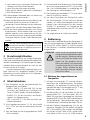
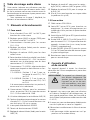
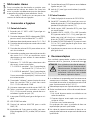
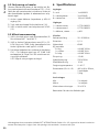
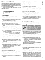
1 Operating Elements
andConnections
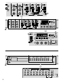
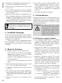
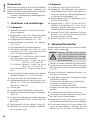
1.1 Front panel
1
6.3 mm input jacks MIC 1 and MIC 2 to connect
mono microphones
2
Bass controls (BASS) and treble controls (TREB)
for the microphone channels MIC 1 and MIC 2
3
Input selector switches for the channels
CH 1 – CH 4
4
Volume controls (faders) for the input channels
CH 1 – CH 4
5 LEVEL controls for both microphone channels
6
Crossfader for fading between two of the
channels CH 1 – CH 4; the respective channels
are selected with the two C.F. ASSIGN switches
(7)
7 Selector switches C.F. ASSIGN to select two of
the channels for fading
C.F. ASSIGN A: position 1, 2 or 3 to select
channel CH 1, CH 2 or CH 3
C.F. ASSIGN B: position 2, 3 or 4 to select
channel CH 2, CH 3 or CH 4
If the respective switch is in 0 position, no chan-
nel is selected.
8
Talkover switch for microphone announce-
ments: in TALK position, the levels of channels
CH 1 – CH 4 are attenuated by 15 dB.
9
Stereo VU meter for the master output AMP (19)
10
Monitoring buttons to monitor the input chan-
nels CH 1 – CH 4 and the master channel via
head phones connected to jack (16)
11 POWER switch
12 POWER LED
13 Master volume control (fader) for the output
AMP (19)
14 3-way equalizer for the outputs; consisting of
the controls HIGH, MID and LOW
15 LEVEL control for the headphones connected
to jack (16)
16
6.3 mm jack to connect stereo headphones
(impedance ≥ 8 Ω)
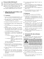
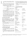
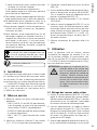
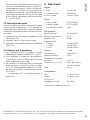
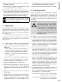
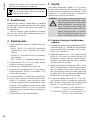
1.2 Rear panel
17 Mains cable for connection to 230 V/ 50 Hz
18 Output REC (RCA jacks) to connect an audio
re corder; the recording level is independent of
the position of the MASTER fader (13)
19
Master output AMP (RCA jacks) to connect
an amplifier
20
Inputs LINE A, LINE B, CD and LINE (RCA jacks)
for the channels CH 1 – CH 4 to connect units
with line level (e. g. tuner, CD / MP3 player,
cassette recorder)
21
Inputs PHONO (RCA jacks) for the channels
CH 1 and CH 2 to connect record players with
magnetic system
22
Connection for the common grounding point,
e. g. for record players
2 Safety Notes
This unit corresponds to all relevant directives of
the EU and is therefore marked with .
WARNING
The unit uses dangerous mains
voltage. Leave servicing to skilled
personnel only. Inexpert handling
may result in electric shock.
•
The unit is suitable for indoor use only. Protect
it against dripping water and splash water, high
air humidity and heat (admissible ambient tem-
perature range 0 – 40 °C).
•
Do not place any vessels filled with liquid, e. g.
drink ing glasses, on the unit.
•
Immediately disconnect the mains plug from the
mains socket if
1. there is visible damage to the unit or to the
mains cable,
2. a defect might have occurred after the unit
was dropped or suffered a similar accident,
3. there are malfunctions.
The unit must in any case be repaired by skilled
personnel.
•
A damaged mains cable must be replaced by
skilled personnel only.
•
Never pull the mains cable to disconnect the
mains plug from the mains socket; always seize
the plug.
•
For cleaning only use a dry, soft cloth; never use
chemicals or water.
English
English Page

8
English
•
If the unit is used for purposes other than orig-
inally intended, if it is not correctly connected
or operated, or if it is not repaired in an expert
way, there is no liability for resulting damage to
persons or material and no guarantee for the
unit can be taken over.
•
Important for U.K. Customers!
The wires in this mains lead are coloured in
accord ance with the following code:
blue = neutral; brown = live
As the colours of the wires in the mains lead
of this appliance may not correspond with the
coloured markings identifying the terminals in
your plug, proceed as follows:
1. The wire which is coloured blue must be con-
nected to the terminal in the plug which is
mark ed with the letter N or coloured black.
2.
The wire which is coloured brown must be
connected to the terminal which is marked
with the letter L or coloured red.
If the unit is to be put out of operation de-
finitively, take it to a local recycling plant
for a disposal which is not harmful to the
environment.
3 Applications
The stereo mixer with four stereo input channels
and two mono microphone channels is suitable
for any desired DJ applications for professional or
private use as well as for PA system applications.
The mixer can be used as a table top unit or
be installed into a rack (482 mm / 19”). For rack
installation, two rack spaces = 89 mm are neces-
sary.
4 Setting into Operation
1)
Connect the audio sources to the corresponding
input jacks:
– LINE A, LINE B, CD and LINE (20) to connect
units with line level (e. g. tuner, CD / MP3
player, cassette recorder);
– PHONO (21) to connect record players with
mag netic system;
– MIC 1 and MIC 2 (1) to connect mono micro-
phones.
2)
Set the input selector switches (3) for the
channels CH 1 – CH 4 to the corresponding
position.
3)
Connect the amplifier to the output jacks
AMP(19).
4)
For any audio recordings, connect a recorder to
the output jacks REC (18). The recording level
is independent of the position of the MASTER
control (13).
5) Connect the plug of the mains cable (17) to a
mains socket (230 V/ 50 Hz).
6)
Before switching on the mixer, the MASTER con-
trol (13) should be set to minimum position to
avoid a strong inrush noise. Then switch on the
mixer with the switch POWER (11). The LED (12)
above the switch lights to show that the mixer
is ready for op er ation.
7) Switch on the units connected.
5 Operation
Prior to the first setting into operation, set all
equalizer controls (2 and 14) to mid-position and
the talkover switch (8) to OFF. Set both C.F. AS-
SIGN switches (7) to position 0 (fading function
switched off).
CAUTION
Never adjust the audio system or
the headphones to a very high vol-
ume. Permanent high volumes may
damage your hearing! Your ear will
get accustomed to high volumes
which do not seem to be that high
after some time. Therefore, do not
further increase a high volume after
getting used to it.
5.1 Mixing the audio sources connected
1)
Use the MASTER fader (13) for adjusting the
total volume of all audio sources connected. For
optimum adjustment of the input channels, set
the MASTER fader to approx.
2
⁄
3
of its maximum
position, e. g. position 7.
2) With the faders (4), adjust the volume for the
input channels CH 1 – CH 4. The VU meter (9)
shows the signal level at the master output AMP
(19). At 0 dB, the mixer is set to maximum gain.
In case of overload, the red LEDs of VU meter
light up.
3) Adjust the desired tone for both outputs REC
(18) and AMP (19) with the 3-way equalizer
(14): with the controls, the LOW, MID and HIGH
frequencies may be attenuated or boosted by
up to 10 dB. In mid-position of the controls
there is no influence on the frequency response.

9
English
4) The crossfader (6) allows fading between two
of the channels CH 1 – CH 4. For this, select the
desired channels with the C.F. ASSIGN switches
A and B (7):
C.F. ASSIGN A: position 1, 2 or 3 to select
channel CH 1, CH 2 or CH 3
C.F. ASSIGN B: position 2, 3 or 4 to select
channel CH 2, CH 3 or CH 4
If the respective switch is in 0 position, no chan-
nel is selected.
When moving the crossfader to the left, the
channel selected with the C.F. ASSIGN A
switch is faded in and when moving the fader
to the right, the channel selected with the
C.F. ASSIGNB switch is faded in. If the fader is in
mid-position, both channels are fed to the out-
puts at the same time. To switch off the fading
function, set both C.F. ASSIGN switches to 0.
5.2 Monitoring the channels
With the monitoring function, it is possible to mon-
itor each individual input channel CH 1 – CH 4 as
well as the MASTER channel via headphones. The
level of the signal monitored is independent of
the position of the corresponding channel fader.
1)
Connect stereo headphones (impedance ≥ 8 Ω)
to the jack (16).
2)
Press the corresponding button (10) of the
channel.
3)
Adjust the desired headphone volume with the
LEVEL control (15).
5.3 Microphone announcements
1) Adjust the desired volume with the LEVEL con-
trols (5) for the microphone channels MIC 1
and MIC 2.
2) Adjust the desired sound with the controls (2):
the low (BASS) and high (TREB) frequencies may
be attenuated or boosted by up to 10 dB.
3) To make it easier to understand a microphone
announcement, the levels of the channels
CH 1 – CH 4 may be attenuated by 15 dB. For
this, set the talkover switch (8) to TALK position.
In OFF position, the talkover function is
switched off.
6 Specifications
Inputs
2 × mic:
. . . . . . . . . . . . . . . 1 mV/ 600 Ω
2 × phono, stereo: . . . . . . . 3 mV/ 50 kΩ
6 × line, stereo: . . . . . . . . . . 150 mV/ 100 kΩ
Outputs
1 × amp, stereo:
. . . . . . . . . 0.775 V/ 600 Ω
1 × record, stereo: . . . . . . . 0.775 V/ 600 Ω
1 × headphone, stereo: . . . . ≥ 8 Ω
General
Frequency range:
. . . . . . . . 20 – 20 000 Hz
THD: . . . . . . . . . . . . . . . . . . 0.1 %
S / N ratio: . . . . . . . . . . . . . . 65 dB
Equalizer controls
3 × low: . . . . . . . . . . . . . ±10 dB /100 Hz
1 × mid . . . . . . . . . . . . . . ±10 dB /1 kHz
3 × high . . . . . . . . . . . . . ±10 dB /10 kHz
Talkover: . . . . . . . . . . . . . . . –15 dB
Power supply: . . . . . . . . . . . 230 V/ 50 Hz
Power consumption: . . . . . . 10 VA
Admissible
ambient temperature:
. . . . . 0 – 40 °C
Dimensions (W × H × D): . . 482 × 89 × 95 mm,
2 rack spaces
Weight:
. . . . . . . . . . . . . . . 2.4 kg
Connections
Mic:
. . . . . . . . . . . . . . . . . . 2 × 6.3 mm jack
Headphones: . . . . . . . . . . . 1 × 6.3 mm jack
All other audio connections: 20 × RCA
Subject to technical modification.
All rights reserved by MONACOR
®
INTERNATIONAL GmbH & Co. KG. No part of this instruction manual may be
reproduced in any form or by any means for any commercial use.
Page is loading ...
Page is loading ...
Page is loading ...
Page is loading ...
Page is loading ...

15
Italiano
Se il crossfader viene aperto verso sinistra, si in-
serisce il canale selezionato con C.F. ASSIGNA,
spostandolo verso destra si attiva il canale sele-
zionato con C.F. ASSIGN B. Se tutti e due i canali
sono destinati alle uscite, il crossfader deve stare
in po si zione centrale. Per disattivare la funzione
di cross fading, posizionare i due commutatori
C.F. ASSIGN sullo 0.
5.2 Preascolto dei canali
Con una cuffia è possibile il preascolto singolo
di tutti i canali d'ingresso CH 1 – CH 4 nonché del
canale delle somme MASTER. Il livello del segnale
ascoltato è indipendente dalla posizione del rela-
tivo fader.
1) Collegare una cuffia stereo (impedenza ≥ 8 Ω)
con la presa (16).
2) Premere il tasto (10) del relativo canale.
3)
Impostare il volume della cuffia con il regolatore
LEVEL (15).
5.3 Annunci con il microfono
1)
Con i regolatori LEVEL (5), regolare il volume
desiderato dei canali microfono MIC 1 e MIC 2.
2) Con i regolatori (2) impostare i toni desiderati:
i bassi (BASS) e gli alti (TREB) possono essere
alzati o abbassati fino a 10 dB.
3)
Per rendere più comprensibile il messaggio
detto attraverso il microfono, i livelli dei canali
CH 1 – CH 4 possono essere abbassati di 15 dB.
Per fare ciò spostare il commutatore talkover
(8) su TALK.
In posizione OFF, la funzione talkover è
disattivata.
6 Dati tecnici
Ingressi
2 × mic:
. . . . . . . . . . . . . . . 1 mV/ 600 Ω
2 × phono, stereo: . . . . . . . 3 mV/ 50 kΩ
6 × line, stereo: . . . . . . . . . . 150 mV/ 100 kΩ
Uscite
1 × amp, stereo:
. . . . . . . . . 0,775 V/ 600 Ω
1 × record, stereo: . . . . . . . 0,775 V/ 600 Ω
1 × uscita cuffia, stereo: . . . ≥ 8 Ω
Dati generali
Banda passante:
. . . . . . . . . 20 – 20 000 Hz
Fattore di distorsione: . . . . . 0,1 %
Rapporto S / R: . . . . . . . . . . . 65 dB
Regolatore toni
3 × bassi: . . . . . . . . . . . . ±10 dB /100 Hz
1 × medi: . . . . . . . . . . . . ±10 dB /1 kHz
3 × alti: . . . . . . . . . . . . . . ±10 dB /10 kHz
Talkover: . . . . . . . . . . . . . . . –15 dB
Alimentazione: . . . . . . . . . . 230 V/ 50 Hz
Potenza assorbita: . . . . . . . . 10 VA
Temperatura d'impiego
ammessa: . . . . . . . . . . . . . . 0 – 40 °C
Dimensioni (L × H × P): . . . . 482 × 89 × 95 mm,
2 unità di altezza
Peso:
. . . . . . . . . . . . . . . . . . 2,4 kg
Collegamenti
Mic:
. . . . . . . . . . . . . . . . . . 2 × jack 6,3 mm
Cuffia: . . . . . . . . . . . . . . . . 1 × jack 6,3 mm
Tutti gli altri
collegamenti audio: . . . . . . 20 × RCA
Con riserva di modifiche tecniche.
La MONACOR
®
INTERNATIONAL GmbH & Co. KG si riserva ogni diritto di elaborazione in qualsiasi forma delle
presenti istruzioni per l’uso. La riproduzione – anche parziale – per propri scopi commerciali è vietata.
Page is loading ...
Page is loading ...
Page is loading ...
Page is loading ...
Page is loading ...

21
Español
(HIGH) pueden modificarse de ±10 dB. Si los
reglajes están en la posición media, no hay nin-
guna modificación de respuesta en frecuencia.
4)
Con el crossfader (6) se puede cambiar entre
dos canales CH 1 – CH 4. Para esto seleccionar
los canales deseados con los conmutadores
C.F.ASSIGN A y B (7):
C.F. ASSIGN A: Posición 1, 2 o 3 para seleccionar
el canal CH 1, CH 2 o CH 3
C.F. ASSIGN B: Posición 2, 3 o 4 para seleccionar
el canal CH 2, CH 3 o CH 4
Si el conmutador concernido está en la posi-
ción0, no hay ningún canal seleccionado.
Accionando el crossfader hacia la izquierda se
utiliza el canal seleccionado por el posiciona-
miento del conmutador C.F. ASSIGN A. Accio-
nando el cross fader hacia la derecha se utiliza
el canal seleccionado por el posicionamiento
del conmutador C.F. ASSIGN B. En posición me-
diana los dos canales se dirigen hacia la salida.
Para apagar la función cross fader, es necesa-
rio poner los conmutadores C.F. ASSIGN en
posición 0.
5.2 Pre-escucha de los canales
La función pre-escucha permite escuchar las entra-
das CH 1 – CH 4 y el canal MASTER en un auricular;
el nivel de esta señal es independiente de la posi-
ción del fader del canal correspondiente.
1)
Conectar un auricular estéreo (impedancia
≥8 Ω) a la toma (16).
2) Pulsar la tecla (10) del canal.
3)
Con el reglaje LEVEL (15) regular el volumen
del auricular.
5.3 Anuncios micro DJ
1)
Regular con los reglajes LEVEL (5) para los cana-
les micro MIC 1 y MIC 2 el volumen deseado.
2)
Regular la tonalidad (2) deseado: los graves
(BASS) y los agudos (TREB) pueden modificarse
de ±10 dB.
3)
Para una mejor comprensión de una anuncio
micro, los niveles de los canales CH 1 – CH 4 pue-
den ser bajados de 15 dB. Para esto, posicionar
el conmutador talkover (8) en posición TALK.
En posición OFF esta función está fuera de
servicio.
6 Características técnicas
Entradas
2 × mic:
. . . . . . . . . . . . . . . 1 mV/ 600 Ω
2 × phono estéreo: . . . . . . . 3 mV/ 50 kΩ
6 × line estéreo: . . . . . . . . . 150 mV/ 100 kΩ
Salidas
1 × amp estéreo:
. . . . . . . . 0,775 V/ 600 Ω
1 × record estéreo: . . . . . . . 0,775 V/ 600 Ω
1 × auricular estéreo: . . . . . ≥ 8 Ω
General
Banda pasante:
. . . . . . . . . . 20 – 20 000 Hz
Tasa de distorsión: . . . . . . . . 0,1 %
Relación señal / ruido: . . . . . . 65 dB
Reglaje de tonalidades
3 × graves: . . . . . . . . . . . ±10 dB /100 Hz
1 × medios: . . . . . . . . . . . ±10 dB /1 kHz
3 × agudos: . . . . . . . . . . . ±10 dB / 10 kHz
Talkover: . . . . . . . . . . . . . . . –15 dB
Alimentación: . . . . . . . . . . . 230 V/ 50 Hz
Consumo: . . . . . . . . . . . . . . 10 VA
Temperatura ambiente: . . . . 0 – 40 °C
Dimensiones (L × A × P): . . . 482 × 89 × 95 mm,
2 U
Peso: . . . . . . . . . . . . . . . . . . 2,4 kg
Conexiones
Mic:
. . . . . . . . . . . . . . . . . . 2 × jack 6,3 mm
Auricular: . . . . . . . . . . . . . . 1 × jack 6,3 mm
Otras conexiones audio: . . . 20 × RCA
Sujeto a modificaciones técnicas.
Manual de instrucciones protegido por el copyright de MONACOR
®
INTERNATIONAL GmbH & Co. KG. Toda
reproducción mismo parcial para fines comerciales está prohibida.
Page is loading ...
Page is loading ...
Page is loading ...
Page is loading ...
Page is loading ...
Page is loading ...
Page is loading ...
Page is loading ...
Page is loading ...
Page is loading ...
Page is loading ...
Page is loading ...

MONACOR INTERNATIONAL GmbH & Co. KG • Zum Falsch 36 • 28307 Bremen • Germany
Copyright
©
by MONACOR INTERNATIONAL. All rights reserved. A-0342.99.03.09.2016
-
 1
1
-
 2
2
-
 3
3
-
 4
4
-
 5
5
-
 6
6
-
 7
7
-
 8
8
-
 9
9
-
 10
10
-
 11
11
-
 12
12
-
 13
13
-
 14
14
-
 15
15
-
 16
16
-
 17
17
-
 18
18
-
 19
19
-
 20
20
-
 21
21
-
 22
22
-
 23
23
-
 24
24
-
 25
25
-
 26
26
-
 27
27
-
 28
28
-
 29
29
-
 30
30
-
 31
31
-
 32
32
-
 33
33
-
 34
34


Ask a question and I''ll find the answer in the document
Finding information in a document is now easier with AI
in other languages
- italiano: IMG Stage Line MPX-622/SW Manuale utente
- français: IMG Stage Line MPX-622/SW Manuel utilisateur
- español: IMG Stage Line MPX-622/SW Manual de usuario
- Deutsch: IMG Stage Line MPX-622/SW Benutzerhandbuch
- Nederlands: IMG Stage Line MPX-622/SW Handleiding
- português: IMG Stage Line MPX-622/SW Manual do usuário
- dansk: IMG Stage Line MPX-622/SW Brugermanual
- svenska: IMG Stage Line MPX-622/SW Användarmanual
- suomi: IMG Stage Line MPX-622/SW Ohjekirja
Related papers
Other documents
-
Monacor 06.1850 Datasheet
-
IMG STAGELINE MPX-44/SW User manual
-
-
-
-
Trust Tytan Stage 2.1 Installation guide
-
-
Omnitronic PM-4010 Pro User manual
-
Omnitronic PM-3010 Pro User manual
-
IMG STAGELINE MPX-20USB User manual