Page is loading ...

68-877-01 Rev. E
05 11
VGA Matrix Switchers
MVX 44 / 48 / 84 / 88 Series
User Guide
Matrix Switchers

This symbol is intended to alert the user of important operating and mainte-
nance (servicing) instructions in the literature provided with the equipment.
This symbol is intended to alert the user of the presence of uninsulated
dangerous voltage within the product’s enclosure that may present a risk of
electric shock.
Caution
Read Instructions • Read and understand all safety and operating instructions before using the equipment.
Retain Instructions • The safety instructions should be kept for future reference.
Follow Warnings • Follow all warnings and instructions marked on the equipment or in the user information.
Avoid Attachments • Do not use tools or attachments that are not recommended by the equipment
manufacturer because they may be hazardous.
Warning
Power sources • This equipment should be operated only from the power source indicated on the product. This
equipment is intended to be used with a main power system with a grounded (neutral) conductor. The third
(grounding) pin is a safety feature, do not attempt to bypass or disable it.
Power disconnection • To remove power from the equipment safely, remove all power cords from the rear of
the equipment, or the desktop power module (if detachable), or from the power source receptacle (wall plug).
Power cord protection • Power cords should be routed so that they are not likely to be stepped on or pinched
by items placed upon or against them.
Servicing • Refer all servicing to qualified service personnel. There are no user-serviceable parts inside. To prevent
the risk of shock, do not attempt to service this equipment yourself because opening or removing covers may
expose you to dangerous voltage or other hazards.
Slots and openings • If the equipment has slots or holes in the enclosure, these are provided to prevent
overheating of sensitive components inside. These openings must never be blocked by other objects.
Lithium battery • There is a danger of explosion if battery is incorrectly replaced. Replace it only with the
same or equivalent type recommended by the manufacturer. Dispose of used batteries according to the
manufacturer’s instructions.
Ce symbole sert à avertir l’utilisateur que la documentation fournie avec le
matériel contient des instructions importantes concernant l’exploitation et la
maintenance (réparation).
Ce symbole sert à avertir l’utilisateur de la présence dans le boîtier
de l’appareil de tensions dangereuses non isolées posant des risques
d’électrocution.
Attention
Lire les instructions• Prendre connaissance de toutes les consignes de sécurité et d’exploitation avant
d’utiliser le matériel.
Conserver les instructions• Ranger les consignes de sécurité afin de pouvoir les consulter à l’avenir.
Respecter les avertissements • Observer tous les avertissements et consignes marqués sur le matériel ou
présentés dans la documentation utilisateur.
Eviter les pièces de xation • Ne pas utiliser de pièces de fixation ni d’outils non recommandés par le
fabricant du matériel car cela risquerait de poser certains dangers.
Avertissement
Alimentations • Ne faire fonctionner ce matériel qu’avec la source d’alimentation indiquée sur l’appareil. Ce
matériel doit être utilisé avec une alimentation principale comportant un fil de terre (neutre). Le troisième
contact (de mise à la terre) constitue un dispositif de sécurité : n’essayez pas de la contourner ni de la
désactiver.
Déconnexion de l’alimentation• Pour mettre le matériel hors tension sans danger, déconnectez tous les
cordons d’alimentation de l’arrière de l’appareil ou du module d’alimentation de bureau (s’il est amovible) ou
encore de la prise secteur.
Protection du cordon d’alimentation • Acheminer les cordons d’alimentation de manière à ce que personne
ne risque de marcher dessus et à ce qu’ils ne soient pas écrasés ou pincés par des objets.
Réparation-maintenance • Faire exécuter toutes les interventions de réparation-maintenance par un
technicien qualifié. Aucun des éléments internes ne peut être réparé par l’utilisateur. Afin d’éviter tout danger
d’électrocution, l’utilisateur ne doit pas essayer de procéder lui-même à ces opérations car l’ouverture ou le
retrait des couvercles risquent de l’exposer à de hautes tensions et autres dangers.
Fentes et orices • Si le boîtier de l’appareil comporte des fentes ou des orifices, ceux-ci servent à empêcher les
composants internes sensibles de surchauffer. Ces ouvertures ne doivent jamais être bloquées par des objets.
Lithium Batterie • Il a danger d’explosion s’ll y a remplacment incorrect de la batterie. Remplacer uniquement
avec une batterie du meme type ou d’un ype equivalent recommande par le constructeur. Mettre au reut les
batteries usagees conformement aux instructions du fabricant.
Safety Instructions • English
Consignes de Sécurité • Français
Sicherheitsanleitungen • Deutsch
Dieses Symbol soll dem Benutzer in der im Lieferumfang enthaltenen
Dokumentation besonders wichtige Hinweise zur Bedienung und Wartung
(Instandhaltung) geben.
Dieses Symbol soll den Benutzer darauf aufmerksam machen, daß im Inneren
des Gehäuses dieses Produktes gefährliche Spannungen, die nicht isoliert sind
und die einen elektrischen Schock verursachen können, herrschen.
Achtung
Lesen der Anleitungen • Bevor Sie das Gerät zum ersten Mal verwenden, sollten Sie alle Sicherheits-und
Bedienungsanleitungen genau durchlesen und verstehen.
Aufbewahren der Anleitungen • Die Hinweise zur elektrischen Sicherheit des Produktes sollten Sie
aufbewahren, damit Sie im Bedarfsfall darauf zurückgreifen können.
Befolgen der Warnhinweise • Befolgen Sie alle Warnhinweise und Anleitungen auf dem Gerät oder in der
Benutzerdokumentation.
Keine Zusatzgeräte • Verwenden Sie keine Werkzeuge oder Zusatzgeräte, die nicht ausdrücklich vom
Hersteller empfohlen wurden, da diese eine Gefahrenquelle darstellen können.
Vorsicht
Stromquellen • Dieses Gerät sollte nur über die auf dem Produkt angegebene Stromquelle betrieben werden.
Dieses Gerät wurde für eine Verwendung mit einer Hauptstromleitung mit einem geerdeten (neutralen) Leiter
konzipiert. Der dritte Kontakt ist für einen Erdanschluß, und stellt eine Sicherheitsfunktion dar. Diese sollte nicht
umgangen oder außer Betrieb gesetzt werden.
Stromunterbrechung • Um das Gerät auf sichere Weise vom Netz zu trennen, sollten Sie alle Netzkabel aus der
Rückseite des Gerätes, aus der externen Stomversorgung (falls dies möglich ist) oder aus der Wandsteckdose
ziehen.
Schutz des Netzkabels • Netzkabel sollten stets so verlegt werden, daß sie nicht im Weg liegen und niemand
darauf treten kann oder Objekte darauf- oder unmittelbar dagegengestellt werden können.
Wartung • Alle Wartungsmaßnahmen sollten nur von qualiziertem Servicepersonal durchgeführt werden.
Die internen Komponenten des Gerätes sind wartungsfrei. Zur Vermeidung eines elektrischen Schocks
versuchen Sie in keinem Fall, dieses Gerät selbst öffnen, da beim Entfernen der Abdeckungen die Gefahr eines
elektrischen Schlags und/oder andere Gefahren bestehen.
Schlitze und Öffnungen • Wenn das Gerät Schlitze oder Löcher im Gehäuse aufweist, dienen diese zur
Vermeidung einer Überhitzung der empndlichen Teile im Inneren. Diese Öffnungen dürfen niemals von
anderen Objekten blockiert werden.
Litium-Batterie • Explosionsgefahr, falls die Batterie nicht richtig ersetzt wird. Ersetzen Sie verbrauchte Batterien
nur durch den gleichen oder einen vergleichbaren Batterietyp, der auch vom Hersteller empfohlen wird.
Entsorgen Sie verbrauchte Batterien bitte gemäß den Herstelleranweisungen.
Este símbolo se utiliza para advertir al usuario sobre instrucciones impor-
tantes de operación y mantenimiento (o cambio de partes) que se desean
destacar en el contenido de la documentación suministrada con los equipos.
Este símbolo se utiliza para advertir al usuario sobre la presencia de elemen-
tos con voltaje peligroso sin protección aislante, que puedan encontrarse
dentro de la caja o alojamiento del producto, y que puedan representar
riesgo de electrocución.
Precaucion
Leer las instrucciones • Leer y analizar todas las instrucciones de operación y seguridad, antes de usar el
equipo.
Conservar las instrucciones • Conservar las instrucciones de seguridad para futura consulta.
Obedecer las advertencias • Todas las advertencias e instrucciones marcadas en el equipo o en la
documentación del usuario, deben ser obedecidas.
Evitar el uso de accesorios • No usar herramientas o accesorios que no sean especificamente
recomendados por el fabricante, ya que podrian implicar riesgos.
Advertencia
Alimentación eléctrica • Este equipo debe conectarse únicamente a la fuente/tipo de alimentación eléctrica
indicada en el mismo. La alimentación eléctrica de este equipo debe provenir de un sistema de distribución
general con conductor neutro a tierra. La tercera pata (puesta a tierra) es una medida de seguridad, no
puentearia ni eliminaria.
Desconexión de alimentación eléctrica • Para desconectar con seguridad la acometida de alimentación
eléctrica al equipo, desenchufar todos los cables de alimentación en el panel trasero del equipo, o desenchufar
el módulo de alimentación (si fuera independiente), o desenchufar el cable del receptáculo de la pared.
Protección del cables de alimentación • Los cables de alimentación eléctrica se deben instalar en lugares
donde no sean pisados ni apretados por objetos que se puedan apoyar sobre ellos.
Reparaciones/mantenimiento • Solicitar siempre los servicios técnicos de personal calicado. En el interior no
hay partes a las que el usuario deba acceder. Para evitar riesgo de electrocución, no intentar personalmente la
reparación/mantenimiento de este equipo, ya que al abrir o extraer las tapas puede quedar expuesto a voltajes
peligrosos u otros riesgos.
Ranuras y aberturas • Si el equipo posee ranuras o orificios en su caja/alojamiento, es para evitar el
sobrecalientamiento de componentes internos sensibles. Estas aberturas nunca se deben obstruir con otros
objetos.
Batería de litio • Existe riesgo de explosión si esta batería se coloca en la posición incorrecta. Cambiar esta
batería únicamente con el mismo tipo (o su equivalente) recomendado por el fabricante. Desachar las baterías
usadas siguiendo las instrucciones del fabricante.
Instrucciones de seguridad • Español
安全须知 • 中文
这个符号提示用户该设备用户手册中有重要的操作和维护说明。
这个符号警告用户该设备机壳内有暴露的危险电压,有触电危险。
注意
阅读说明书 • 用户使用该设备前必须阅读并理解所有安全和使用说明。
保存说明书 • 用户应保存安全说明书以备将来使用。
遵守警告 • 用户应遵守产品和用户指南上的所有安全和操作说明。
避免追加 • 不要使用该产品厂商没有推荐的工具或追加设备,以避免危险。
警告
电源 • 该设备只能使用产品上标明的电源。 设备必须使用有地线的供电系统供电。 第三条线
(地线)是安全设施,不能不用或跳过 。
拔掉电源 • 为安全地从设备拔掉电源,请拔掉所有设备后或桌面电源的电源线,或任何接到市
电系统的电源线。
电源线保护 • 妥善布线, 避免被踩踏,或重物挤压。
维护 • 所有维修必须由认证的维修人员进行。 设备内部没有用户可以更换的零件。为避免出现
触电危险不要自己试图打开设备盖子维修该设备。
通风孔 • 有些设备机壳上有通风槽或孔,它们是用来防止机内敏感元件过热。 不要用任何东
西挡住通风孔。
锂电池 • 不正确的更换电池会有爆炸的危险。必须使用与厂家推荐的相同或相近型号的电池。
按照生产厂的建议处理废弃电池。

FCC Class A Notice
This equipment has been tested and found to comply with the limits for a Class A digital device, pursuant to part 15
of the FCC Rules. Operation is subject to the following two conditions:
This device may not cause harmful interference.
1. This device must accept any interference received, including interference that may cause undesired operation.
The Class A limits are designed to provide reasonable protection against harmful interference when the equipment
is operated in a commercial environment. This equipment generates, uses, and can radiate radio frequency energy
and, if not installed and used in accordance with the instruction manual, may cause harmful interference to radio
communications. Operation of this equipment in a residential area is likely to cause harmful interference, in which
case the user will be required to correct the interference at his own expense.
NOTE: This unit was tested with shielded cables on the peripheral devices. Shielded cables must be used with
the unit to ensure compliance with FCC emissions limits.
For more information on safety guidelines, regulatory compliances, EMI/EMF compliance, accessibility,
and related topics, click here.

Conventions Used in this Guide
In this user guide, the following are used:
NOTE: A note draws attention to important information.
TIP: A tip provides a suggestion to make working with the application easier.
CAUTION: A caution indicates a potential hazard to equipment or data.
WARNING: A warning warns of things or actions that might cause injury, death, or
other severe consequences.
Commands are written in the fonts shown here:
^AR Merge Scene,,Op1 scene 1,1 ^B 51 ^W^C
[01] R 0004 00300 00400 00800 00600 [02] 35 [17] [03]
E
X!
*
X2!
*
X2$
*
X2#
*
X2%
CE
}
NOTE: For commands and examples of computer or device responses mentioned
in this guide, the character “0” is used for the number zero and “O”
represents the capital letter “o.”
Computer responses and directory paths that do not have variables are written in the font
shown here:
Reply from 208.132.180.48: bytes=32 times=2ms TTL=32
C:\Program Files\Extron
Variables are written in slanted form as shown here:
ping xxx.xxx.xxx.xxx —t
SOH R Data STX Command ETB ETX
Selectable items, such as menu names, menu options, buttons, tabs, and field names are
written in the font shown here:
From the File menu, select New.
Click the OK button.
Copyright
© 2011 Extron Electronics. All rights reserved.
Trademarks
All trademarks mentioned in this guide are the properties of their respective owners.

Contents
Introduction ............................................ 1
About this Guide ............................................. 1
About the Switchers ........................................ 1
Features ........................................................... 2
Installation .............................................. 4
Mounting the Switcher .................................... 4
Cabling and Rear Panel Views .......................... 4
Video and Audio Input Connections ............. 5
Video and Audio Output Connections .......... 5
Remote Connection ..................................... 6
Power Connection ....................................... 7
Operation ................................................ 8
Front Panel Controls and Indicators .................. 8
Infrared Sensor and Power/audio/data LED ... 9
Input and Output Selection Controls
and Indicators ............................................. 9
Control Buttons and LEDs .......................... 10
I/O Selection and Audio/video Controls
and Indicators ........................................... 10
Operations ..................................................... 12
Definitions ................................................. 12
Powering up the Switcher .......................... 12
Creating a Set of Ties ................................. 13
Viewing the Configuration ......................... 17
Using Presets.............................................. 20
Adjusting Input Audio Gain
and Attenuation ....................................... 23
Setting the Output Audio Level .................. 28
Front Panel Security Lockout
(Executive Mode) ...................................... 28
Clearing all Ties and Presets ....................... 29
Resetting the System to Factory Defaults .... 30
Memory ..................................................... 30
Optimizing the Audio..................................... 31
Troubleshooting ............................................. 31
Worksheets .................................................... 32
Worksheet Example 1:
System Equipment .................................... 32
Worksheet Example 2:
Daily Configuration ................................... 33
Worksheet Example 3:
Test Configuration .................................... 34
Configuration Worksheet ........................... 35
Remote Operation .................................36
IR Remote Control ......................................... 36
Simple Instruction Set Control ........................ 37
Host-to-Switcher Instructions ..................... 37
Switcher-initiated Messages ....................... 37
Switcher Error Responses ........................... 38
Using the Command and Response Table ... 38
Loading Firmware Using an SIS Command . 44
Matrix Switchers Control Program .................. 46
Installing the Software ............................... 46
Starting the Software ................................. 47
Using the Software .................................... 47
Updating the Firmware .............................. 49
Windows Buttons, Drop Boxes,
and Trash Can ........................................... 52
Using Emulation Mode ............................... 56
Using the Help System ............................... 56
Reference Information ..........................57
Specifications ................................................. 57
Part Numbers and Accessories ........................ 60
MVX Part Numbers .................................... 60
Included Parts ............................................ 60
Optional Accessories .................................. 61
Cables ....................................................... 61
Mounting the Switcher .................................. 63
Tabletop Use .............................................. 63
UL Rack-Mounting Guidelines .................... 63
Mounting Instructions ................................ 63
MVX 44 / 48 / 84 / 88 VGA Matrix Switchers • Contents v

MVX 44 / 48 / 84 / 88 VGA Matrix Switchers • Contents vi

Introduction
• About this Guide
• About the Switchers
• Features
About this Guide
This guide contains installation, configuration, and operating information for the Extron®
MVX VGA Matrix Switchers.
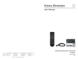
About the Switchers
The Extron MVX Series VGA matrix switchers (see figure 1) is a family of computer video
matrix switchers that distribute any VGA or component/HDTV video (or other high resolution
video) and audio input to any combination of outputs. The MVX Series switchers can route
multiple input/output ties simultaneously. The switchers input and output high resolution
video on 15-pin HD connectors. They input audio on 3.5 mm mini jacks and output audio on
3.5 mm captive screw connectors. There are four matrix sizes available:
• MVX 44 (four inputs by four outputs)
• MVX 48 (four inputs by eight outputs)
• MVX 84 (eight inputs by four outputs)
• MVX 88 (eight inputs by eight outputs)
VID
50/60 Hz
1
2
3
4
Y
/VID
B-Y
H/
HV
R
/R-Y
V
G
/Y
B
/B-Y
RS-232
LAN
RESET
ACT
LINK
RGB/R-Y,Y,B-Y
YC
SDI
R-Y
/C
RGB/R-Y,Y,B-Y/YC/VID
100-240V .3A
I
N
P
U
T
O
U
T
P
U
T
I
N
P
U
T
O
U
T
P
U
T
100-240V 0.3A
50-60Hz
MVX 88 VGA A
RS-232
OUTPUTS
L
R
7
L
R
8
L
R
5
L
R
6
L
R
3
L
R
4
L
R
1
L
R
2
C
U S
LISTED
1T23
I.T.E.
1
2
3
4
INPUTS
5
6
7
8
1
2
OUTPUTS
3
4
5
6
7
8
DVD-RW/-R RECORDING
Precision Cinema Progressive
VSC 500
SCAN CONVERTER
SIZE
MIN/MAX
NEXTMENU
FREEZE
RESET
IR
CENTER/PAN/SIZE
Welcome to
Extron
MVX Series
Matrix Switcher
Extron
VSC 500
Video Scan
Converter
Extron
DVS 304
Digital Video Scaler
Audio In
Audio
In
Audio
Out
Laptop
VCR
Flat Panel
Displays
Projector
RS-232
Laptop
Laptop
DVD
1
31
42
31
42
3
1
42
2
3
100
LINK
ACT
COM
IR
INPUT
RELAY
TX RX
R
IPL 250
®
ON
OFF
DISPLAY
MUTE
SCREEN
UP
SCREEN
DOWN
VCR
DVD
DOC
CAM
LAPTOP
PC
Extron
XPA 1002
Power Amplier
Extron
SI 28
Surface-mount
Speakers
TCP/IP
TouchLink
™
Control
System
XPA 1002
1 2
LIMITER/PROTECT
SIGNAL
OVER
TEMP
Figure 1. Typical MVX 88 VGA A Application
MVX 44 / 48 / 84 / 88 VGA Matrix Switchers • Introduction 1

NOTE: The switchers can also distribute S-video and composite video with applicable
adapters.
The MVX switcher can be locally controlled from the front panel or remotely controlled
via its rear panel RS-232 serial port or an optional IR 501 Small Matrix Infrared (IR) Remote
Control (part number 70-336-01).
Features
Video — These switchers input and output VGA – UXGA RGBHV, RGBS, RGsB, RsGsBs
video, or component/HDTV signals on 15-pin HD female connectors.
Bandwidth — Bandwidth is 300 MHz (–3 dB). This high bandwidth allows the switchers to
switch high resolution video with no loss of signal quality.
Audio input — These switchers input unbalanced stereo audio signals on 3.5 mm mini
jacks.
Audio output — These switchers output balanced or unbalanced stereo audio signals on
3.5 mm, 5-pole captive screw terminals.
Audio input gain/attenuation — You can set the input audio gain or attenuation (–18 dB
to +10 dB) via the RS-232 port or from the front panel. Individual input audio levels can be
adjusted so there are no noticeable volume differences between sources and allows for the
best headroom and signal-to-noise ratio. This function also eliminates the need for separate
preamps or attenuators when used with professional (higher line level) and consumer (lower
line level) audio equipment.
Audio output level switch — The audio level of each output can be set to either –10 dBV
(consumer level) or +4 dBu (pro level) via RS-232 control only.
Audio follow — Audio can be switched with the corresponding video input. Audio follow
switching can be done via front panel control, optional IR 501 control, or the RS-232 port.
Audio breakaway — Audio can be broken away from its corresponding video input signal.
Audio breakaway switching can be done via front panel control, optional IR 501 control, or
the RS-232 port.
Switching flexibility — Provides individually buffered, independent matrix switched
outputs with audio follow and audio breakaway for audio versions.
• Any input to any or all outputs
• Quick multiple tie — Multiple inputs can be switched to multiple outputs
simultaneously. This allows all displays (outputs) to change from source to source at the
same time.
Operational flexibility — Operations such as input/output selection and setting of presets
can be performed on the front panel, via the RS-232 port, or using the optional IR 501 small
matrix universal remote control. The RS-232 port allows remote control via a PC or control
system.
• Front panel controller — The MVX series front panel controller feature supports
touch-of-a-button input and output selection, preset creation and selection, and audio
gain and attenuation control.
• RS-232 control — The RS-232 port of the switcher allows remote control via a PC or
control system using the Extron Simple Instruction Set (SIS™) or the included Matrix
Switchers Control Program.
• Optional IR remote control — The MVX switchers are remote controllable, using the
optional IR 501 Small Matrix IR Remote Control.
MVX 44 / 48 / 84 / 88 VGA Matrix Switchers • Introduction 2

Upgradeable firmware — The firmware that controls the operation of the switcher can
be upgraded in the field via the RS-232 port, without taking the switcher out of service.
Firmware upgrades are available for download on the Extron website, www.extron.com,
and they can be installed using the Windows-based control program.
Global memory presets — Sixteen global memory presets are a time-saving feature that
lets you set up and store input/output configurations in advance. You can then recall those
configurations, when needed, with a few simple steps. On each model, there are as many
presets available from the front panel as there are input and output buttons:
• MVX 44s have 8 presets available on the front panel
• MVX 48s and MVX 84s have 12 presets available on the front panel
• MVX 88s have 16 presets available on the front panel
On smaller MVXs, presets that are not available from the front panel are still available under
RS-232 or optional IR 501 control.
Rack mountable — With the included rack mounting kit, the switchers can be mounted in
any conventional 19-inch wide rack.
Under-desk mountable — With an optional desk mounting kit, the switchers can be
mounted under a desk, podium, or other furniture.
Front panel security lockout (executive mode) — If an MVX Series switcher is installed
in an open area where operation by unauthorized personnel may be a problem, a security
lockout feature can be implemented. When the front panel is locked, a special button
combination is required to unlock the front panel controller before it can be operated. Ties
can still be viewed.
When the front panel is locked out, the switcher can still be operated via the RS-232 link.
Power supply — The internal 100 VAC to 240 VAC, 50/60 Hz 30 watts power supply
provides worldwide power compatibility.
MVX 44 / 48 / 84 / 88 VGA Matrix Switchers • Introduction 3

Installation
This sections details the installation of the MVX VGA Matrix Switchers, including:
• Mounting the Switcher
• Cabling and Rear Panel Views
Mounting the Switcher
CAUTION: Installation and service must be performed by authorized personnel only.
Detailed mounting instructions can be found in the “Reference Information“ section
at the end of this guide. The 1U high matrix switchers can be placed on a tabletop or
mounted on a rack shelf. Use the included hardware for rack mounting.
Cabling and Rear Panel Views
All connectors are on the rear panel. Depending on the model, the switcher can have up to
eight high resolution video and stereo audio inputs and eight video and audio outputs.
Figure 2 shows an MVX 88 VGA A video and audio switcher. Other switcher models are
housed in the same 1U enclosures, but have fewer input connectors, output connectors, or
both to accommodate the different matrix sizes that they provide.
100-240V 0.3A
50-60Hz
MVX 88 VGA A
RS-232
OUTPUTS
L
R
7
L
R
8
L
R
5
L
R
6
L
R
3
L
R
4
L
R
1
L
R
2
C
U S
LISTED
1T23
I.T.E.
1
2
3
4
INPUTS
5
6
7
8
1
2
3
4
OUTPUTS
3
4
5
6
7
8
5 4
1 2 3
Figure 2. MVX 88 VGA A High Resolution Video Matrix Switcher
MVX 44 / 48 / 84 / 88 VGA Matrix Switchers • Installation 4

Video and Audio Input Connections
a RGB video inputs — Connect the analog computer-video sources to
1
these 15-pin HD female connectors.
NOTE: Most laptop or notebook computers have an external video port, but they
require special commands to output the video to that connector. Also,
a laptop screen shuts off once that port is activated. See the user guide
for the computer for details, or contact the Extron S3 Sales and Technical
Support Hotline for a list of common laptop keyboard commands (see
the contact numbers on the last page of this guide for the Extron office
nearest you).
Audio inputs — Connect the
unbalanced stereo audio sources to these
1
3.5 mm mini stereo jacks for unbalanced audio input. Figure 3 shows how to
wire the audio plug.
Tip (L) Sleeve (Gnd)
Tip (L)
Ring (R)
Sleeve (Gnd)
Figure 3. Audio Input Connector Wiring
Video and Audio Output Connections
b RGB video output connectors — Connect RGBHV video displays to these
15-pin HD female connectors for each output.
NOTES: • The MVX switchers can also switch RGBS, RGsB, RsGsBs, or
component/HDTV video.
• The MVX switchers do not alter the video signal in any way. The signal
output by the switcher is in the same format as the input.
c Balanced or unbalanced audio output connectors — These 3.5 mm, 5-pole captive
screw connectors output the selected unamplified, line level audio. Connect audio
devices, such as an audio amplifier or powered speakers.
See figure 4 to properly wire an output connector. Use the supplied tie-wrap to strap
the audio cable to the extended tail of the connector.
Ring
Sleeve(s)
Tip
Tip
Ring
Sleeve(s)
Tip
Tip
Unbalanced Stereo Output Balanced Stereo Output
NO GROUND HERE.
NO GROUND HERE.
LR
Do not tin the wires!
Figure 4. Captive Screw Connector Wiring for Audio Output
CAUTION: For unbalanced audio, connect the sleeves to the ground contact.
DO NOT connect the sleeves to the negative (-) contacts.
MVX 44 / 48 / 84 / 88 VGA Matrix Switchers • Installation 5

NOTES: • The length of exposed wires is critical. The ideal length is 3/16 inch (5 mm).
• If the stripped section of wire is longer than 3/16 inch, the exposed
wires may touch, causing a short circuit.
• If the stripped section of wire is shorter than 3/16 inch, wires can be
easily pulled out even if tightly fastened by the captive screws.
• Figure 4 on the preceding page identifies the tip, ring, and sleeve. A
mono audio connector consists of the tip and sleeve. A stereo audio
connector consists of the tip, ring and sleeve. If you are wiring a captive
screw connector from an existing unbalanced audio cable, the white
insulated wire is typically the left channel (tip) and the red insulated wire
is typically the right channel (sleeve). There is no reliable standard for
existing balanced audio cables.
The audio level for each input can be individually set, via the front panel or RS-232,
to ensure that the level on the output does not vary from input to input. See the
“Operation” section and the “Remote Operation” section.
By default, the audio follows the video switch. Audio breakaway, which is commanded
via the front panel, via RS-232 control using SIS commands or the Windows-based
control program, or via optional IR 501 control, allows you to select from any one of the
audio input sources. See the “Operation” section, the “Remote Operation” section,
and the IR 501 Small Matrix IR Remote Control User Guide.
Remote Connection
d RS-232 connector — Connect a host device, such as a computer or control system, to
the switcher via this 9-pin D connector (figure 5) for remote control of the switcher.
Pin RS-232 Function
2TX Transmit data (-)
3RX Receive data (+)
4—Not used
5 Gnd Signal ground
6—Not used
Not used
Not used
7—
8—
—
51
96
Female
Hardwired IR9
1—Not used
Figure 5. RS-232 Port Pin Assignment
NOTE: The cable used to connect the RS-232 port to a computer or control
system may need to be modified by removing pins or cutting wires. If you
encounter problems while operating under RS-232 control (the switcher
may hang up), pins 1, 4, 6, 7, and 8 may need to be disconnected. Either
cut the wire to pins 1, 4, and 6 through 8 in a hard-shelled connector or
remove pins 1, 4, and 6 through 8 from a molded plug.
See the “Remote Operation” section for definitions of the SIS commands and details
on how to install and use the control software.
Using the hardwired IR input on pin 9, you can use a control system with IR-learning
capabilities to operate the switcher just as if you were using an IR 501 remote control.
The control system must first “learn” the IR command from an IR 501, after which it
sends the same commands to the MVX via pin 9.
MVX 44 / 48 / 84 / 88 VGA Matrix Switchers • Introduction 6

Power Connection
e AC power connector — Plug a standard IEC power cord into this connector to connect
the switcher to a 100 VAC to 240 VAC, 50 or 60 Hz power source.
MVX 44 / 48 / 84 / 88 VGA Matrix Switchers • Introduction 7

Operation
This section describes the front panel operation of the MVX VGA Matrix Switcher, including:
• Front Panel Controls and Indicators
• Operations
• Optimizing the Audio
• Troubleshooting
• Worksheets
Front Panel Controls and Indicators
The number of input and output buttons and LEDs that each MVX Series VGA matrix
switcher provides varies with the number of inputs and outputs.
Figure 6 shows the front panel of an 8-input, 8-output video and audio switcher. Other
switcher models have fewer input and/or output buttons to accommodate the different
matrix sizes that they provide.
Many of the buttons and LEDs on figure 6 have dual functions.
MVX SERIES
VGA/AUDIO MATRIX SWITCHER
I/O
AUD
AUDIO SETUP
PRESET
VID
IR
+dB
-dB
ENTER
2
7
6
5
2 4
1
INPUTS
OUTPUTS
8
3
1
8
6
5
4
3
7
2 6 75
3 4
1 10 911 8
Figure 6. MVX 88 VGA A Front Panel
MVX 44 / 48 / 84 / 88 VGA Matrix Switchers • Operation 8

Infrared Sensor and Power/audio/data LED
a Infrared remote sensor — This sensor receives infrared (IR) signals from the optional
IR 501 small matrix universal remote control. The IR remote control must be pointed
within 30 degrees of this sensor for best results.
Operation of the IR 501 remote control is described in the IR 501 Small Matrix IR Remote
Control User Guide.
NOTE: Keep the switcher out of bright light to prevent interference with the IR
signals from the IR 501 remote control.
b Power/data/audio LED —
• When lit, the Power LED indicates that power is applied to the matrix switcher.
• When blinking off and on, the Power LED indicates that an IR signal has been
received.
• In Audio Setup mode, the Power LED also serves as an audio meter that is tied to
output 1. The LED blinks frequently when the audio level of the selected input has
been adjusted to the –10 dBV internal reference level. (In Audio Setup mode, the
audio of the selected input is automatically tied to output 1.) See “Adjusting Input
Audio Gain and Attenuation” on page 23 and “Optimizing the Audio” on
page 31.
Input and Output Selection Controls and Indicators
NOTE: If the switcher has fewer than eight inputs or outputs, it has fewer input or
output buttons and LEDs.
c Input buttons and LEDs — The input buttons and LEDs select and identify inputs.
Alternate preset selection function — The input buttons and LEDs also serve as preset
selection buttons and indicators, allowing you to select presets to either save or recall.
A more detailed explanation of the presets functions is included in “Using Presets”,
beginning on page 20.
d Output buttons and LEDs — The output buttons and LEDs select and identify outputs.
Alternate preset selection function — The output buttons and LEDs also serve as
preset selection buttons and indicators, allowing you to select presets to either save
or recall. A more detailed explanation of the presets functions is included in “Using
Presets”, beginning on page 20.
Alternate audio indication function — The Output 1 through Output 3 LEDs also
serve as the input audio level indicators, each indicating a range of 6 dB when lit:
• Output 1 LED off = 0 dB to 5 dB
• Output 1 LED lit = 6 dB to 11 dB
• Output 1 and 2 LED lit = 12 dB to 17 dB
• Output 1 through Output 3 LEDs lit = 18 dB
See “Adjusting Input Audio Gain and Attenuation” on page 23.
Alternate audio adjustment function — On 8-output switchers, the Output 7
and Output 8 buttons and LEDs also serve as the Down (
<
) and Up (
>
) controls and
indicators. See item
j
and item
k
.
MVX 44 / 48 / 84 / 88 VGA Matrix Switchers • Operation 9

Control Buttons and LEDs
e Enter button — The Enter button saves changes when you set up a new configuration.
To create a simple configuration:
• Specify video, audio, or both (see controls [item g] and [item h]).
• Press the desired input button (item c).
• Press one or more desired output buttons (item d).
• Press the Enter button.
f Preset button and LED — The Preset button activates either Save Preset mode or
Recall Preset mode. Save Preset mode saves a configuration as a preset. Recall Preset
mode recalls and activates a previously-defined preset. The Preset button indicates Save
Preset mode when it is blinking and Recall Preset mode when it lights steadily.
Alternate reset function — This button is also used to clear all ties and presets.
See “Clearing all Ties and Presets” on page 29.
I/O Selection and Audio/video Controls and Indicators
g I/O and Audio Setup button —
• Press and release — Pressing the I/O button cycles through video and audio, video
only, or audio only for input and output selection. See the Video and Audio LEDs
(item h) for the sequence.
• Press and hold — The I/O button also serves as the Audio Setup mode selection
button. To enable the Audio Setup mode, press and hold the Audio Setup button
for about 2 seconds until the Audio Setup LED (item i) lights. In Audio Setup
mode, you can view and/or change the current audio level setting for each input
(see “Adjusting Input Audio Gain and Attenuation” on page 23.
Audio Setup mode times out after approximately 30 seconds of inactivity.
Alternate reset function — This button is also used to perform a system reset
(see “Resetting the System to Factory Defaults” on page 30.
h Video/+dB LED and Audio/–dB LED —
• I/O selection — The Video and Audio LEDs indicate whether video and audio,
video only, or audio only will be selected using the input buttons (item c) and
output buttons (item d).
Pressing the I/O button advances through a cycle of video and/or audio selections
(see figure 7).
MVX SERIES
VGA/AUDIO MATRIX SWITCHER
I/O
AUD
AUDIO SETUP
Default
= Lit, = unlit.
VID
+dB
-dB
AUD
VID
+dB
-dB
Video Only
AUD
VID
+dB
-dB
Audio Only
AUD
VID
+dB
-dB
Video and
Audio
AUD
VID
+dB
-dB
PressPressPress Press
Figure 7. Video and/or Audio Selection Cycle
• Audio Setup mode — The –dB and +dB LEDs indicate the polarity of the audio
level setting. See “Adjusting Input Audio Gain and Attenuation” on page 23.
Both LEDs light to indicate unity gain (0 dB).
MVX 44 / 48 / 84 / 88 VGA Matrix Switchers • Operation 10

i Audio Setup LED — The Audio Setup LED lights red to indicate that the switcher
is in Audio Setup mode. See “Adjusting Input Audio Gain and Attenuation” on
page 23.
Alternate IR error function — The Audio Setup LED also indicates errors when you
use an IR 501 small matrix remote control. The LED lights for approximately 1 second
when the switcher receives an unexpected or out-of-sequence IR command from the
remote control. The switcher otherwise ignores the command.
j Down (
<
) button and LED — The
<
button decreases the audio gain for a selected
input. Press and release the button to decrease the gain by 1 dB or press and hold the
button to decrease the gain by 3 dB per second until the button is released or the lower
limit is reached.
NOTES: • On 4-output switchers, this button and LED stand alone.
• On 8-output switchers, this button and LED are secondary functions of
the Output 7 button and LED.
The
<
LED flashes once in Audio Setup mode to indicate each 1 dB decrease in the input
audio gain. See “Adjusting Input Audio Gain and Attenuation” on page 23.
The
<
LED lights steadily in Audio Setup mode to indicate that the adjustment has
reached the maximum attenuation (-18 dB).
k Up (
>
) button and LED — The
>
button increases the gain for a selected input. Press
and release the button to increase the audio level by 1 dB or press and hold the button
to increase the audio level by 3 dB per second until the button is released or the upper
limit is reached.
NOTES: • On 4-output switchers, this button and LED stand alone.
• On 8-output switchers, this button and LED are secondary functions of
the Output 8 button and LED.
The
>
LED flashes once in Audio Setup mode to indicate each 1 dB increase in the input
audio gain. See “Adjusting Input Audio Gain and Attenuation” on page 23.
The
>
LED lights steadily in Audio Setup mode to indicate that the adjustment has
reached the maximum gain (+10 dB).
MVX 44 / 48 / 84 / 88 VGA Matrix Switchers • Operation 11

Operations
The following paragraphs define matrix switcher terms and then detail the power-up process
and then provide sample procedures for creating ties, sets of ties, and configurations;
changing a configuration; viewing ties, sets of ties, and configurations; saving a preset;
recalling a preset; viewing and adjusting the audio level; and selecting the front panel
security lockout.
Definitions
The following Extron matrix switcher terms are used throughout this manual:
Tie — An input-to-output connection
Set of ties — An input tied to two or more outputs. (An output can never be tied to more
than one input.)
Configuration — Consists of one or more ties or one or more sets of ties
Current configuration — The configuration that is currently active in the switcher (also
called configuration 0)
Global memory preset — A configuration that has been stored. Sixteen global memory
presets can be stored in memory. The input and output buttons select preset memory
locations to load or retrieve. When a preset is retrieved from memory, it becomes the current
configuration. On each model, there are as many presets available from the front panel as
there are input and output buttons:
• The MVX 44 has 8 presets available on the front panel.
• The MVX 48 and MVX 84 have 12 presets available on the front panel.
• The MVX 88 has 16 presets available on the front panel.
On smaller MVX models, presets that are not available from the front panel are still
available under RS-232 or optional IR 501 control.
Powering up the Switcher
1. Plug in the switcher. On all switcher models, power is automatically applied when the
power cord is connected to an AC source. When AC power is applied, the switcher
performs a self-test and initialization that sequences the front panel LEDs on and off
from left to right. A successful power up self-test and initialization leaves the power LED
on, the Video and Audio LEDs on, and all other LEDs off.
The current configuration, all presets, and all input audio levels are saved in non-volatile
memory within 5 seconds of a change or exiting Audio Setup mode. When power is
applied, the most recent configuration is retrieved. The previous presets remain intact.
NOTE: Wait at least 5 seconds after changing any configuration, saving a preset,
or exiting Audio Setup mode. Before 5 seconds have elapsed, changes that
you have made may not have been saved.
If an error occurs during the self-test, the switcher locks up and does not operate. If your
switcher locks up on power-up, call the Extron S3 Sales and Technical Support Hotline.
See the last page of this guide for the phone number in your region of the world.
2. Plug in all system components and turn on the input devices (such as computers or
HDTV set-top boxes) and the output devices.
3. Set the input devices to output video using the operating instructions for each device.
4. Create a tie (see below). The selected input image should appear at the selected output.
If no image appears, see “Troubleshooting” on page 31.
MVX 44 / 48 / 84 / 88 VGA Matrix Switchers • Operation 12

Creating a Set of Ties
You can create a set of ties, changing the current configuration, by using the front panel
buttons. Change the current configuration as follows:
1. Select video, audio, or both to configure by pressing the I/O button as necessary.
2. Select the desired input and one or more outputs by pressing the input and output
buttons.
3. Press and release the Enter button.
4. Repeat steps 1 through 3 to create additional ties until the desired configuration is
complete.
NOTES: • Only one video input and one audio input can be tied to an output.
• If a tie is made between an input and an output, and the selected output
was previously tied to another input, the older tie is broken in favor of
the newer tie.
• Output LEDs light when an input is selected to indicate current ties. Press
and release the associated output buttons to clear unwanted outputs.
• If, when you are configuring video and audio ties, the Audio LED blinks
and the Video LED is on after you have selected an input or output, the
LEDs indicate audio breakaway, meaning that the audio ties are not the
same as the video ties for that input.
• If an input with no tie is selected, only the LED for that input lights.
• As each output is selected, the associated output LED blinks to indicate
a tentative tie until you press the Enter button or the 5-second timeout
expires. LEDs for outputs that were already tied to the input light steadily.
Outputs that are already tied can be left on, along with new blinking
selections, or toggled off by pressing the associated output button.
• If you inadvertently press the wrong input or output button, wait
approximately 5 seconds. The input and output button selections time
out and are abandoned.
Example 1: Create a set of video and audio ties
In the following example, input 5 is tied to outputs 3, 4, and 8. The example shows the front
panel indications that result from your actions.
NOTE: This example assumes that there are no ties in the current configuration.
1. Select video and audio for the tie: If necessary, press and release the I/O button to
cycle through the selections until the both LEDs light.
I/O
AUD
VID
Press the button.
The video LED lights when video is selected.
The audio LED lights when audio is selected.
2. Select an input: Press and release the input 5 button.
7
6
5
2 4
1
INPUTS
8
3
Press and release the Input 5 button.
The Input 5 LED lights to indicate that input 5 is selected.
MVX 44 / 48 / 84 / 88 VGA Matrix Switchers • Operation 13

3. Select the outputs: Press and release the output 3, output 4, and output 8 buttons.
NOTE: The entire set of ties can be canceled at this point by by waiting for the
5-second input/output button timeout to occur.
7
6
5
2 4
1
8
3
OUTPUTS
Press and release the Output 3, 4, and 8 buttons.
The LEDs blink to indicate that the selected input will be tied to these outputs.
4. Confirm the change: Press and release the Enter button.
ENTER
3 4
8
5
INPUTS
OUTPUTS
The LEDs for the selected input and the
selected outputs light steadily for approximately
1 second to indicate the tie and then go out.
Press the Enter button to
confirm the configuration
change.
1 second
The current configuration is now input 5 video and audio tied to output 3, output 4, and
output 8 (see figure 8).
Input 5 (video/audio) tied
to outputs 3, 4, and 8.
Input
Output
3
4
8
5
Video
Audio
Figure 8. Example 1 Configuration
MVX 44 / 48 / 84 / 88 VGA Matrix Switchers • Operation 14
/