Dometic RM2351, RM2354, RM2410, RM2451, RM2454, RM2510, RM2551, RM2554, RM2620, DM2652, DM2662, DM2663, NDA140, RM3762, RM2820, DM2852,DM2862, RM3962, NDM1062, RM1350, RM1350SL Operating instructions
- Category
- Fridges
- Type
- Operating instructions

REVISION B
Form No. 3315546.000 8/19
(French 3315547.000_B)
©2019 Dometic Corporation
LaGrange, IN 46761
RM2351
RM2354
RM2410
RM2451
RM2454
INSTALLATION
INSTRUCTIONS
RM2510
RM2551
RM2554
RM2620
DM2652
DM2662
DM2663
RM3762
RM2820
DM2852
DM2862
RM3962
NDM1062
RM1350
RM1350SL
USA
Service Oce
Dometic Corporation
1120 North Main Street
Elkhart, IN 46514
For Service Center Or
Dealer Locations
Please Visit:
www.Dometic.com
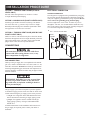
FOR YOUR SAFETY
If you smell gas:
1. Open windows.
2. Don’t touch electrical switches.
3. Extinguish any open ame.
4. Immediately call your gas supplier.
FOR YOUR SAFETY
Do not store or use gasoline or other am-
mable vapors and liquids in the vicinity of
this or any other appliance.
Improper installation, adjustment,
alteration, service or maintenance can cause
injury or property damage. Refer to this man-
ual. For assistance or additional information
consult a qualied installer, service agency
or the gas supplier.
If the refrigerator stops cooling - or - if
it emits an ammonia smell, immediately
turn the refrigerator off and contact a
Service Center.
NDA1402

- 2 -
NOTES

- 3 -
CERTIFICATION AND CODE REQUIREMENTS ................................................................................ 4
INSTALLATION PREPARATION ......................................................................................................... 5
VENT APPLICATION TYPES ............................................................................................................ 8
INSTALLATION PROCEDURE ......................................................................................................... 13
REFRIGERATOR REMOVAL ............................................................................................................ 27
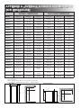
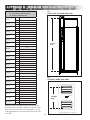
APPENDIX A - OVERALL & ROUGH IN DIMENSIONS FOR ENCLOSURE .................................... 28
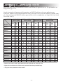
APPENDIX B - MINIMUM VENTILATION HEIGHTS ........................................................................ 29
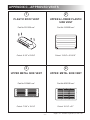
APPENDIX C - APPROVED VENTS ................................................................................................. 30
APPENDIX D - VENT INSTALLATION PROCEDURES .................................................................... 34
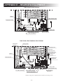
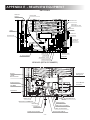
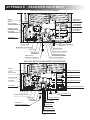
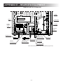
APPENDIX E - REARVIEW EQUIPMENT ......................................................................................... 35
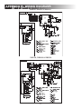
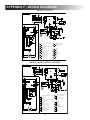
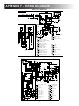
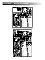
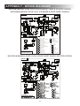
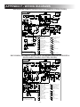
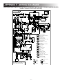
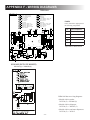
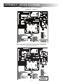
APPENDIX F - WIRING DIAGRAMS ................................................................................................ 42
CONTENTS
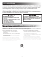
SYMBOLS
The following symbols are used throughout this manual:
This is the safety alert symbol. It is used to alert you to personal injury hazards. Obey all safety
messages that follow this symbol to avoid possible injury or death.
WARNING indicates a hazardous situation which, if not avoided, could result in death or serious injury.
CAUTION, used with the safety alert symbol, indicates a hazardous situation which, if not avoided,
could result in minor or moderate injury.
NOTICE is used to address practices not related to personal injury.
Information
Step-by-step instructions

- 4 -
This appliance is certied under the latest edition of ANSI Z21.19•CSA 1.4 Refrigerators using gas fuel. The installation must
conform with local codes, or in absence of local codes, the following standards as applicable.
In the U.S. the installation must conform with:
• National Fuel Gas Code, ANSI Z223.1/NFPA 54
(latest edition).
• Recreational Vehicles Code, ANSI A119.2 (latest edition).
• Manufactured Home Construction and Safety Standard,
Title 24 CFR, Part 3280.
If an external electrical source is utilized, the refrigerator,
when installed, must be electrically grounded in accordance
with local codes or, in the absence of local codes, the National
Electrical Code, ANSI/NFPA 70 - (latest edition).
In CANADA, the installation must conform with:
• Natural Gas and Propane Installation Code, CSA B149.1
• CSA Z240 RV Series, Recreational Vehicles.
• Current CSA Z240.4, Gas-equipped Recreational Vehicles
and Mobile Housing.
If an external electrical service is utilized, the refrigerator,
when installed, must be electrically grounded in accordance
with local codes or, in the absence of local codes, the Canadi-
an Electrical Code CSA C22.1, Parts and - (latest edition).
CERTIFICATION AND CODE REQUIREMENTS
-
ties. Be aware of possible safety hazards when seeing alert symbols on the refrigerator as well as in this manual.
Appearance of your product may vary from illustrations shown in this document.
Not all procedures in this document will apply to your product. Read and follow the information pertaining to
INTRODUCTION
Any modications or deviations:
• Can lead to carbon monoxide leaking into the
living area.
• Can reduce cooling performance and/or result in
damage to the refrigerator.
• Will void agency certications.
• Will void refrigerator warranty.
Any deviation from the prescribed installation
instructions in this manual must have prior written
approval and safety certication verication from
Dometic Corporation.

- 5 -
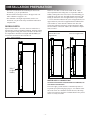
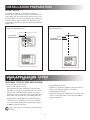
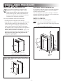
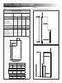
INSTALLATION PREPARATION
ASSEMBLING THE
REFRIGERATOR ENCLOSURE
The ventilation compartment is part of the product
safety certication and must not be used for any other
purpose than securing air for combustion and ventila-
tion of ue gases and warm air.
Ventilation
Compartment
Enclosure
Refrigerator
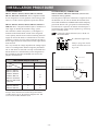
CLEARANCES (FIG 2)
Top (G) 0” Min to 1/4” Max
Side (K) 0” Min to 1/4” Max
Bottom (L) 0” Min to 0” Max
Rear (M
1
) 0” Min to 1” Max
1
The distance between the refrigerator cooling unit and the wall or
bae behind it.
Read and follow these points:
• The refrigerator must be level and installed in a substantial
enclosure, see “APPENDIX A”.
•
weight of the refrigerator and its contents.
• Ensure that any adjacent heat sources, (e.g. furnace exhaust
• All joints in the enclosure must be sealed to prevent gas
leakage into the living area.
• The enclosure must be free of exposed materials that may
potentially damage the refrigerator, e.g. screw tips, staples,
etc.
• A wood strip must be in place across the upper opening
of the enclosure. The top frame of the refrigerator will be
anchored to the wood strip with screws, see FIG 2.
• The refrigerator must not be installed directly on
carpeting:
- Carpeting must be removed or protected by a metal or
wood panel beneath the appliance, which extends at least
full width and depth of the appliance.
-
portion behind the refrigerator will need to be painted
with an anti-wicking paint to protect against water or
moisture that comes in through the side or roof vent.
• It is required that OEM installed components such as
current-carrying conductors (i.e. wiring), plumbing, etc. -
except for those required to supply the refrigerator - shall
not pass through the refrigerator enclosure except where:
G
K K
L
M
FIG 2 - CLEARANCES
Wood
Strip
FIG 1 - ENCLOSURE
- OEM installed components inside of the refrigerator
enclosure are contained outside of the ventiliation com-
partment by means of permanently securing them (e.g.
behind paneling, behind batt-type insulation, inside of
paneled storage space above refrigerator) in such a man-
ner that OEM installed components will not come into
contact with the refrigerator.
- Applications for which there are no alternatives except
to have these OEM installed components pass through
the ventilation compartment the following requirements
must be met: 1) current carrying conductors (120V and
12V) and conductor routing - except for those required
to supply the refrigerator - must be protected by conduit,
raceway, covering boards or equilvalent and in all cases
must meet or exceed the requirements of the current
publication of NFPA70 and article 551 of the NEC, 2)
all OEM installed components shall maintain a mini-
mum clearance of 1/2" clearance from the cooling unit
to ensure that they will not come into contact with the
heated boiler or tubing, 3) the routing of OEM installed
components shall not impede the ventilation path for
proper operation or combustion, 4) OEM installed com-
ponents must not come into contact with the refrigerator
mounting rails or frame and the refrigerator should not
routing of OEM installed components.
CLEARANCES
zero (0) inch minimum clearance at the sides, rear, top, and
for correct refrigerator performance.
Failure to adhere to the above installation criteria could cre-
ate a combustion hazard.

- 6 -
INSTALLATION PREPARATION
TOP AND SIDES
See “APPENDIX A” for rough in dimensions. Dimensions will
vary by model. If there is more than 1/4” between either side
or the top of the refrigerator and the inside of the refrigerator
-
the performance of the unit. See Insulation note below for
additional details.
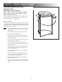
INSULATION NOTE!
- Any insulation used must be securely attached to the
enclosure walls and ceiling in order to prevent it from
shifting when the refrigerator is installed in enclosure.
- If there is a void space above the refrigerator, insulation
should be secured with spray adhesive to the top of the
- Trim insulation. Cut it 2-3” shorter than the depth of the
refrigerator box, see FIG 3 below.
- Insulation must not come in contact with the cooling unit!
issues and possible damage to the refrigerator.
FIG 3 - INSULATION
compartment and sides and top of refrigerator.
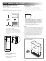
VENTILATION REQUIREMENTS
Ventilation is one of the requirements for proper cooling unit
operation. Clearances and the use of vents ensure a natural
draft which is necessary for good refrigeration.
Make sure to read and follow these points:
•
vent and one upper exhaust vent.
• Vents should be centered to the back of the refrigerator. If it
-
tion, see “OFFSET VENTS”, page 8.
•
“APPENDIX C”.
• Any obstruction of either of the vent openings is not per-
• Lower vent: Make sure the opening is even with - or - be-
outside. NOTE! Floor must not interfere with or block vent
openings.
FIG 5 - VENT ABOVE FLOOR LEVEL
When lower vent frame is positioned
higher than the refrigerator compart-
• 2 holes with a diameter of 1-3/4”
1 in
2
/ hole free area.)
• Cover holes with a screen
(min. 14 x 14 per inch)
• Holes must be clear of any
obstruction.
1-3/4”
Covered by a screen
COMBUSTION HAZARD. Unburned “Raw” LP
gas is heavier-than-air and can collect at oor level
creating a combustion hazard.
FIG 4 - LOWER VENT
Side
wall
Floor
Weep
hole
•
required to vent these gases to the out-of-doors. Use FIG 5
for details.
2” - 3”
2” - 3”

- 7 -
INSTALLATION PREPARATION
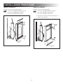
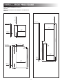
FIG 6 - RECESS DEPTH
FIG 7 - BOX BAFFLE
•
obstructed, e.g. by an open RV door.
• Do not install an awning too close to the upper side vent.
Allow a distance of approx. 6-12”.
• The minimum vent height requirements, listed in “AP-
PENDIX B”
complied with.
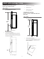
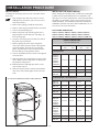
RECESS DEPTH
Spaces of more than 1”, see FIG 6, from rear wall to the re-
frigerator may create performance problems. Fresh air will not
increase the movement of air across the coil.
If there is more than 1” between the inside of the ventila-
tion compartment and cooling unit, it is required to add box
-
ceiling (in board roof vent vent applications) or up to within
come within 1/2"
-
ment, see FIG 7.
Max 1”
(without
BOX BAFFLE
WATER SUPPLY CONNECTION
REFRIGERATOR MODELS EQUIPPED WITH ICE MAKER, ICE
AND WATER DISPENSERS
The water supply system must have a minimum pressure of
15 pounds per square inch gauge (psig). A 1/4” diameter water
line to the water valve should be used at the rear of the refrig-
where it is easily accessible.
1/2" Below
Fins
Roof Vent Applications
Inboard Roof Vent
Applications
BOX BAFFLE

- 8 -
INSTALLATION PREPARATION
VENT APPLICATION TYPES
OFFSET VENTS
of the cooling unit. The vent should be centered over the cool-
Dometic, LLC.
FIG 8 - OFFSET VENT
UPPER AND LOWER SIDE VENT
FIG 9 - OFFSET VENT
SIDE AND ROOF VENT
CENTER OF
REFRIGERATOR
CENTER OF
REFRIGERATOR
CHOOSING TYPE OF VENT APPLICATION
There are four types of applications:
• ROOF VENT APPLICATION
Recommended for typical installations. Check the enclo-
sure depth, see “INSTALLATION PREPARATION > ENCLO-
SURE DEPTH”-
due to radius roof or interference with building materials.
• UPPER AND LOWER SIDE VENT APPLICATION
Choose this type of installation when a roof vent installa-
-
tor must be equipped with fan(s).
• ISLAND APPLICATION
Intended for refrigerators installed on an inside wall and
• CORNER APPLICATION
Intended for refrigerators installed in the rear corner of the
vehicle or in an angled cabinet. The refrigerator must be
equipped with fan(s).
Please refer to page 30, some fans are optional and not
required.

- 9 -
Step Action
1 CHECK VENTILATION HEIGHT.
See “APPENDIX B”.
2 CHECK RECESS DEPTH.
See “INSTALLATION PREPARATION > RECESS
DEPTH”.
lower access vent.
3 INSTALL LOWER SIDE VENT
See “APPENDIX D”.
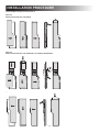
ROOF VENT APPLICATION
INSTALL LOWER SIDE VENT AND ROOF VENT
Minimum
Ventilation
Height
BOX BAFFLE
RECESS
DEPTH
4 INSTALL ROOF VENT
•
See “APPENDIX D”.
•
Inboard installs due to radius roof or
interference with building material.
BOX BAFFLE
RECESS DEPTH
BOX BAFFLE
RECESS DEPTH
VENT APPLICATION TYPES

- 10 -
VENT APPLICATION TYPES
Step Action
1 CHECK VENTILATION HEIGHT.
See “APPENDIX B”.
2 CHECK RECESS DEPTH.
See “INSTALLATION PREPARATION >
RECESS DEPTH”. If required, install a box baf-
picture below.
3 INSTALL LOWER SIDE VENT.
See “APPENDIX D”.
4 INSTALL UPPER SIDE VENT.
See “APPENDIX D”.
UPPER AND LOWER SIDE VENT
APPLICATION
INSTALL UPPER AND LOWER SIDE VENTS
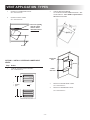
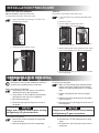
ISLAND APPLICATION
ACCESS PANEL
• A sealed access panel is required when using this
Access is necessary to complete gas connections, gas leak
tests, and periodic service requirements at the rear of the
refrigerator.
Access panel dimensions
• If the refrigerator is located within the vehicle interior it
must be completely sealed to prevent products of com-
bustion or raw gas leakage within the living space! If it
provided, rear access is still required.
• The door or panel should prevent water entry.
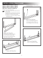
DUCT
An air duct extends downwardly from the refrigerator through
a fan, a fan must be installed in the duct to aid air circulation.
Air for cooling the condenser and absorber is drawn up the
duct from outside the vehicle and exhausted outside the vehi-
cle through an upper duct and vent in a roof of the vehicle.
The duct must be centered horizontally on the back of the
refrigerator and should have the following dimensions:
Length (L): 11-34” min - max values
Width (W): 6.5”
Depth (D): 4-54” min - max values
Fan(s)*
Minimum
Ventilation
Height
* Fan(s) position may vary by model.
BOX BAFFLE
RECESS
DEPTH
FIG 10 - DUCT DIMENSIONS
D
L
W
Center Fan
Horizontally
Min 3”
Max 8”
1/4” x 0.025 metal mesh
22”
14”

- 11 -
VENT APPLICATION TYPES
ISLAND APPLICATION CONT'D
INSTALL DUCT AND ROOF VENT
Step Action
1 CHECK VENTILATION HEIGHT.
See “APPENDIX B”.
2 CHECK RECESS DEPTH.
See “INSTALLATION PREPARATION > RECESS
DEPTH”
lower than access panel.
Minimum
Ventilation
Height
DUCT AND FAN
ACCESS
PANEL
{
ACCESS
PANEL
DUCT
AND
FAN
RECESS DEPTH
3 INSTALL ACCESS PANEL
4 INSTALL DUCT
5 INSTALL ROOF VENT
See “APPENDIX D”.
CORNER APPLICATION
OPTION 1 - INSTALL LOWER SIDE VENT AND
ROOF VENT
Step Action
1 CHECK VENTILATION HEIGHT.
See “APPENDIX B”.
2 CHECK RECESS DEPTH.
See “INSTALLATION PREPARATION > RECESS
DEPTH”. A box bae is required above the
lower access vent.
Minimum
Ventilation
Height
RECESS
DEPTH

- 12 -
2 CHECK RECESS DEPTH.
See “INSTALLATION PREPARATION > RE-
CESS DEPTH”. A box bae is required above
the lower access vent.
3 INSTALL LOWER SIDE VENT.
See “APPENDIX D”.
4 INSTALL UPPER SIDE VENT.
See “APPENDIX D”.
VENT APPLICATION TYPES
Roof vent opening
must be a mini-
mum of 110 in
2
unobstructed free
area.
Rafters
3 INSTALL LOWER SIDE VENT.
See “APPENDIX D”.
4 INSTALL ROOF VENT
See “APPENDIX D”.
OPTION 2 - INSTALL UPPER AND LOWER SIDE
VENTS
Step Action
1 CHECK VENTILATION HEIGHT.
See “APPENDIX B”.
RECESS
DEPTH
Fan*
Minimum
Ventilation
Height
* Fan position may vary by model.
BAFFLE
UPPER SIDE
VENT
LOWER
SIDE VENT

- 13 -
INSTALLING THE REFRIGERATOR
Be careful when installing the refrigerator model
NDM1062. It is equipped with the latest vacuum
insulated panel technology. The insulating panels are
located on the top, back, bottom, sides and doors. If
the surface is punctured, loss of insulation will occur,
resulting in poor refrigerator performance.
For a proper installation, follow these instructions:
• Carefully place the refrigerator in the enclosure.
• Verify that there is a complete seal between the front frame
of the refrigerator and the top, sides and bottom of the
enclosure. A length of sealing strip is applied to the rear
surface of the front frame for this purpose. The sealing
combustion system from the vehicle interior.
RM2351, RM2354, RM2410 and RM2510: Apply a seal-
Be careful not to damage the sealing strip when the
refrigerator is put in place!
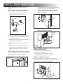
SECURING THE REFRIGERATOR
It is important to follow the sequence in securing refrigerator
in enclosure since failure in doing so can cause leakage be-
tween the frame and cabinet.
After the refrigerator is put in place (ensuring a combustion
seal at the front frame), the refrigerator is to be secured in the
enclosure with screws (not included).
RM2351 & RM2354
1. Four screws installed through the front frame.
(To cover the screw heads, use the plugs in the parts
bag.)
2. One screw installed in the rear base.
2
1
INSTALLATION PROCEDURE
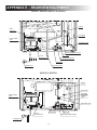
General view. Features may vary by model.
FIG 12 - RM2451, RM2454, RM2551, RM2554, DM2652, DM2662,
DM2663, DM2852, DM2862, RM3762, RM3962, NDM1062, RM1350,
RM1350SL & NDA1402
FIG 11 - RM2351, RM2354, RM2410 & RM2510
FIG 13 - SECURING RM2351 & RM2354
Sealing strip must be width of enclosure.
Sealing
Strip

- 14 -
RM2410 & RM2510
Install the six screws in the following order:
1. Two screws installed through the front base.
2. Two screws installed in the top frame.
3. Two screws installed in the rear base.
INSTALLATION PROCEDURE
FIG 14 - SECURING RM2410 & RM2510
FIG 15 - SECURING RM2620 & RM2820
Sealing
Strip
3 rd.
2 nd.
1 st.
4 th.
1 st.
2 nd.
3 rd.
RM2620 & RM2820
Install the screws in the following order:
1. Two screws installed through the front base.
2. Two screws installed in the top frame.
3. Two screws installed in the rear base.
4. Attach lower front strip after the refrigerator is set
into the cutout opening.

- 15 -
INSTALLATION PROCEDURE
RM2451, RM2454, RM2551, RM2554,
DM2652, DM2662, DM2663, DM2852,
DM2862, RM3762, RM3962, RM1350,
RM1350SL, NDA1402 & NDM1062
Install the screws in the following order:
1. TWO SCREWS INSTALLED THROUGH THE
FRONT BASE.
The refrigerator is provided with a lower front strip
(shipped as a loose part). Attach the front strip after
the refrigerator is set into the cutout opening.
a) Install the lower front strip by sliding it under the
bottom hinge plate(s).
Models with 1 Hinge Plate
The hinge plate can be located on
the left or right side depending
on the door swing. Slip under the
hinge and swing into place.
Models with 2 Hinge Plates
Models with 2 Hinge Plates
One screw through each hinge.
b) Secure the refrigerator and the lower front
strip with two screws.
Models with 1 Hinge Plate
One screw through the hinge and
on the opposite side and then, one
screw through the lower front strip.

- 16 -
3. ONE SCREW INSTALLED IN THE REAR BASE.
OPTIONAL SCREW MAY BE ADDED.
RM2451, RM2454, RM2551, RM2554, DM2652,
DM2662, DM2663, DM2852, DM2862, RM3762,
RM3962 & NDM1062
RM1350. RM1350SL & NDA1402
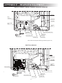
DRAIN WATER HOSE
• Hose must not contact the boiler casing.
• Hose must not be kinked.
• Hose must not be routed uphill at any point.
• Perforated plug must be present at end of hose.
OPTION 1 - THROUGH FLOOR
Check to make sure the supplied hose is long enough – if not,
installer will have to supply extra length of hose.
Ice Maker
Cord
(optional)
2. TWO SCREWS INSTALLED IN THE TOP
FRAME.
RM2451, RM2454, RM2551, RM2554, DM2652,
DM2662, DM2663, DM2852, DM2862 & NDM1062
a) Gently push the tabs out of the hole in the hinge
b) Carefully tilt the top decoration panel and lift to
remove from top frame. Be careful not to damage
the circuit board and wires.
c) Install the two screws in the top frame, the holes
are accessible from underneath.
d) Seal the opening for the screws with aluminum
tape.
e) Replace the top decoration panel. Be careful not
to pinch the wires behind the panel. Make sure
the tabs snap back into the holes in the hinge
plate.
RM3762, RM3962, RM1350, RM1350SL & NDA1402
Fasten the refrigerator with two screws through the
holes underneath the top decoration panel.
Hole for drain
water hose
Boiler
casing
Hose
INSTALLATION PROCEDURE
2
1
General view. Features may vary by model.
General view. Features may vary by model.
General view. Features may vary by model.
Optional
Screw
FIG 16 - DRAIN WATER HOSE

- 17 -
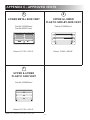
OPTION 2 - THROUGH VENT FRAME (PLASTIC
VENTS ONLY)
Pull end of hose through louvers in vent door. Cut hose
to length. Reinstall perforated plug.
OPTION 3 - HANGING CLIP (PLASTIC VENTS ONLY)
Install clip (part number 3106559.xxx) during vent installa-
tion. Insert hose into “j” portion of clip. Cut hose to length.
Reinstall perforated plug. Hose should be positioned to drain
into uppermost row of louvers in vent door.
OPTION 4 - THROUGH VENT DOOR (SIDE-BY SIDE
PLASTIC VENT ONLY)
drain hose through hole and cut to length. Reinstall perforated
plug on the outside of the vent frame. Apply sealant around
plug to ensure water does not seep into enclosure.
CONNECTIONS
GAS CONNECTION
Hook up to the gas supply line is accomplished at the manual
gas valve, which is furnished with a 3/8” SAE (UNF 5/8” -18)
ALWAYS use a back-up wrench when
loosening and tightening gas connections. All completed con-
nections should be examined for leaks using an approved leak
detection solution.
The gas supply system must incorporate a pressure regulator
to maintain a supply pressure of not more than 11 inches water
column. When testing the gas supply system at test pressures:
• > 1/2 psi
must be disconnected from the gas supply piping system.
• ≤ 1/2 psi - the appliance must be isolated from the gas
supply piping system by closing its individual manual
If detailed instructions on the installation and connection to
the gas supply are required, please contact your dealer or
distributor.
INSTALLATION PROCEDURE
All connections should be routed to avoid direct
contact with boiler casing, burner cover, or any
other components of refrigerator.
EXPLOSION HAZARD. Never use an open ame
to check for gas leaks. Failure to obey this warn-
ing could cause an explosion resulting in death or
severe personal injury.
ELECTRICAL CONNECTION
120 VAC CONNECTION
The refrigerator is equipped with a grounded three-prong plug
for protection against shock hazards. It should be plugged di-
rectly into a properly grounded three-prong receptacle. Do not
cut or remove the grounding prong from this plug!
The free length of the cord is 2 feet. To allow easy access
through the vent door, it is recommended to install the recep-
tacle on the opposite side of the burner assembly and approx.
General view. Features may vary by model.
3-6”
120 VAC
Receptacle
FIG 17 - 120 VAC CONNECTION

- 18 -
INSTALLATION PROCEDURE
Example: If the distance between the refrigerator and the
12 VDC supply is 20 ft., the total wire length is 40 ft. and
a wire size of 10 AWG should be used.
12 VDC CONNECTION
RM2451, RM2551, DM2652, DM2852, RM3762, RM3962,
RM1350, RM1350SL & NDA1402: These refrigerator models
are not designed for 12V DC operation of the cooling system.
However, 12V DC must be supplied to operate the controls.
RM2354, RM2454, RM2554, DM2662, DM2663, DM2862 &
NDM1062: These refrigerator models require a continuous 12
VDC supply to maintain the automatic energy system.
The connection is made to the positive (+) and negative (-)
terminals of the terminal block on back of the refrigerator.
Correct polarity must be observed when connecting to the DC
supply. Do not use the chassis or vehicle frame as one of the
conductors. Connect two wires at the refrigerator and route to
the DC supply. Ensure the connections are clean, tight and free
from corrosion.
of the 12 V cartridge heater and the refrigerator performance.
The 12 VDC heater is fused with a 30 amp. in-line blade fuse.
Ensure that the wires from the battery to the refrigerator are
able to handle the load. Recommended wire sizes are dis-
played in the table below.
MAXIMUM WIRE LENGTH
WIRE
MODEL
Size Length
AWG
ft
RM2351, RM2451
RM2551, DM2652
DM2662, DM2852
DM2862, RM3762
RM3962, NDM1062
RM1350, RM1350SL,
NDA1402
14
12
17
27
RM2354, RM2454
RM2554, DM2663
10
8
17
27
ALTERNATOR (D+) CONNECTION
RM3762, RM3962, RM1350 & RM1350SL (with the auto-
matic door locking system)
The refrigerator requires the connection of a signal wire from
the alternator (D+) in order to maintain the automatic door
travel latch for RM1350, and RM1350SL and the temporary
gas lockout function. The gas operation will automatically
be locked out for a period of 15 minutes when the engine is
. This will prevent gas operation e.g. when stop-
ping at a refueling station.
Connect the vehicles alternator (D+) to the D+ on
the terminal block.
Battery
B+
Alternator signal wire to the refrigerator
D+
ALTERNATOR
Ignition switch
Charge light
D+ (Alternator signal wire)
Valid for refrigerator models
with the automatic door lock-
ing system.
FIG 18 - ALTERNATOR CONNECTION

- 19 -
INSTALLATION PROCEDURE
DOOR AND HANDLE MOUNTING
INSTRUCTIONS
REVERSING THE DOOR SWING
RM2351, RM2354, RM2451, RM2454, RM2551, RM2554,
DM2652, DM2662, DM2663, RM3762, DM2852, DM2862,
RM3962, NDM1062 & NDA1402
A special hinge kit must be used in order to change the door
swing. For conversion kit number, please contact service
point or distributor service department.
RM2410 & RM2510
The refrigerator is equipped with hinges that make it possible
to change the direction the door opens by moving the hinges
to the opposite side. To change the door hinges from one side
to the other, follow these steps:
1. Open the door and remove the two screws hold-
ing the top decoration. (The screws are accessible
from beneath.)
2. Remove the top hinge pin and lift out the door.
3. Unscrew the bottom hinge pin.
4. Remove the plastic cap from the opposite lower
hinge and place it in the hole just “left empty” by
the lower hinge pin.
5. Screw the lower hinge pin in the hole from which
the plastic cap was removed.
6. Before replacing the door on the refrigerator,
remove the catches and move them to the opposite
side of the cabinet.
7. The holes are covered with plastic caps that must
be removed and inserted in the holes that previ-
ously held the catches.
8. Unscrew the handle and move it to the opposite
side of the door.
9. Insert the plastic caps into the holes left open on
the door. (Plastic caps for empty holes are in the
parts bag inside the refrigerator.)
10. Remount the door and hinge pins in the reverse
order of their removal.
11.
door closes easily and the gasket seals well on all
sides.
FIG 19 - RM2410 & RM2510, REVERSING THE DOOR SWING

- 20 -
INSTALLATION PROCEDURE
PANEL DIMENSIONS
MAX. THICKNESS 5/32”
HEIGHT
MAX MIN
WIDTH
MAX MIN
UPPER DOOR
DM2652
DM2662
DM2663
DM2852
DM2862
NDM1062
15-27/32 15-25/32 20-3/4 20-5/8
RM2620 12-3/64 11-31/32 20-9/32 20-13/64
RM2820 14-7/8 14-51/64 22-11/64 22-3/32
RM3762
RM3962
17-3/64 16-31/32 23-25/32 23-11/16
LOWER DOOR / SINGLE DOOR
RM2351
RM2354
26-17/64 26-3/16 19-5/8 19-17/32
RM2410 27-7/16 27-23/64 20-9/32 20-13/64
RM2510 35-5/16 35-15/64 20-9/32 20-13/64
RM2620 32-1/4 32-5/32 20-9/32 20-13/64
RM2820 35-5/16 35-15/64 22-11/64 22-3/32
RM2451
RM2454
DM2652
DM2662
DM2663
32-9/16 32-1/2 20-3/4 20-5/8
RM2551
RM2554
DM2852
DM2862
NDM1062
38-11/16 38-5/8 20-3/4 20-5/8
RM3762 32-7/16 32-23/64 23-25/32 23-11/16
RM3962 41-39/64 41-9/16 23-25/32 23-11/16
INSTALLING THE DOOR PANEL(S)
Before starting the mounting work, read this section thorough-
ly. Make sure the panel dimensions are in compliance with
those given in “PANEL DIMENSIONS”. After having mounted
the panel(s) as described in “MOUNTING INSTRUCTIONS”,
install the handles. For installation instructions for RM3762
& RM3962 (stainless steel doors) and for NDM1062, see “IN-
STALLING THE DOOR HANDLES”.
DOOR PANEL DIMENSIONS
RM2351, RM2354, RM2410, RM2451, RM2454, RM2510,
RM2620, DM2652, DM2662, DM2663, RM2551, RM2554,
RM3762, RM2820, DM2852, DM2862, RM3962 & NDM1062
RM2620 & RM2820
To change the door hinges from one side to the other, follow
these steps:
1. Open the upper door and remove the two screws
holding the top decoration. (The screws are acces-
sible from beneath.)
2. Remove the top hinge pin and lift out the door.
3. Remove center hinge pin and lift out the lower door.
4. Unscrew the bottom hinge pin.
5. Remove the plastic cap from the opposite lower
hinge and place it in the hole just “left empty” by
the lower hinge pin.
6. Screw the lower hinge pin in the hole from which
the plastic cap was removed.
7. Before replacing the doors on the refrigerator,
remove the catches and move them to the opposite
side of the cabinet. The holes are covered with
plastic caps that must be removed and inserted in
the holes that previously held the catches.
8. Unscrew the handles and move them to the opposite
side of the door.
9. Insert the plastic caps into the holes left open on the
doors. (Plastic caps for empty holes are in the parts
bag inside the refrigerator.)
10. Remount the doors and hinge pins in the reverse
order of their removal.
11.
door closes easily and the gasket seals well on all
sides.
FIG 20 - RM2620 & RM2820, REVERSING THE DOOR SWING
Page is loading ...
Page is loading ...
Page is loading ...
Page is loading ...
Page is loading ...
Page is loading ...
Page is loading ...
Page is loading ...
Page is loading ...
Page is loading ...
Page is loading ...
Page is loading ...
Page is loading ...
Page is loading ...
Page is loading ...
Page is loading ...
Page is loading ...
Page is loading ...
Page is loading ...
Page is loading ...
Page is loading ...
Page is loading ...
Page is loading ...
Page is loading ...
Page is loading ...
Page is loading ...
Page is loading ...
Page is loading ...
Page is loading ...
Page is loading ...
Page is loading ...
Page is loading ...
Page is loading ...
Page is loading ...
-
 1
1
-
 2
2
-
 3
3
-
 4
4
-
 5
5
-
 6
6
-
 7
7
-
 8
8
-
 9
9
-
 10
10
-
 11
11
-
 12
12
-
 13
13
-
 14
14
-
 15
15
-
 16
16
-
 17
17
-
 18
18
-
 19
19
-
 20
20
-
 21
21
-
 22
22
-
 23
23
-
 24
24
-
 25
25
-
 26
26
-
 27
27
-
 28
28
-
 29
29
-
 30
30
-
 31
31
-
 32
32
-
 33
33
-
 34
34
-
 35
35
-
 36
36
-
 37
37
-
 38
38
-
 39
39
-
 40
40
-
 41
41
-
 42
42
-
 43
43
-
 44
44
-
 45
45
-
 46
46
-
 47
47
-
 48
48
-
 49
49
-
 50
50
-
 51
51
-
 52
52
-
 53
53
-
 54
54


Dometic RM2351, RM2354, RM2410, RM2451, RM2454, RM2510, RM2551, RM2554, RM2620, DM2652, DM2662, DM2663, NDA140, RM3762, RM2820, DM2852,DM2862, RM3962, NDM1062, RM1350, RM1350SL Operating instructions
- Category
- Fridges
- Type
- Operating instructions
Ask a question and I''ll find the answer in the document
Finding information in a document is now easier with AI
Related papers
-
Dometic RM2351 RM2354 RM2451 RM2454 RM2551 RM2554 DM2652 DM2662 DM2663 DM2852 DM2862 NDM1062 Operating instructions
-
-
-
-
-
-
-
-
Dometic RM1350 User manual
-
Other documents
-
Broan H6HK, 25 Kw 240V,1-Phase Electric Heater Kit Product information
-
Handy Home Products 18153-5 Operating instructions
-
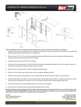 Hot Box Installation-HBM-8-10 Installation guide
-
Scotsman KBTABS - Use with ABS and CME686 or CME810 Operating instructions
-
DCS ADR2-24 Operating instructions
-
Hoover VCN 6185/1B User manual
-
Norcold DC0041CR, DC0061CR Installation guide
-
-
Haier CFE633CWE User manual
-
Norcold DE-0061/ EV-0061 Installation guide
