Design Information
Microwave Oven
Model
available
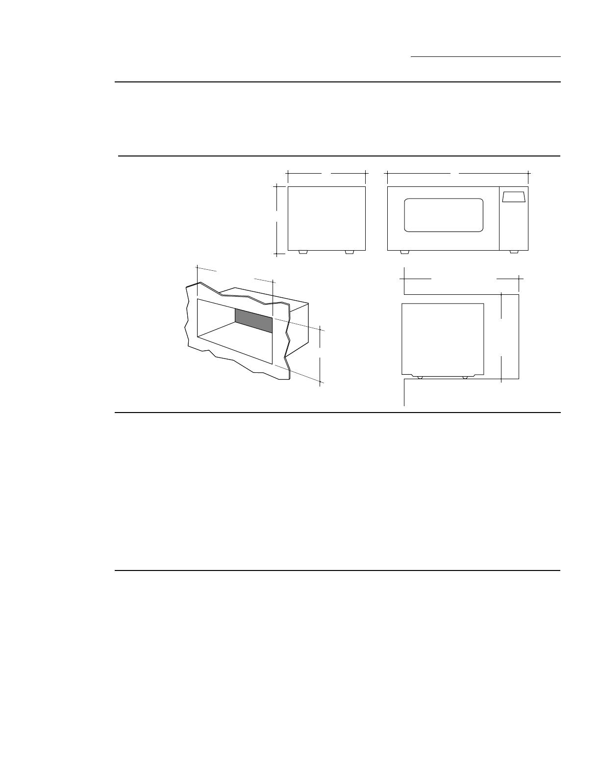
Dimensions
and clearances
Installation
options
3
ZEM200 Series
Electronic microwave ovens
available in black, white and
stainless steel
A - 12-5/16" (284 mm)
B - 23-13/16" (605 mm)
C - 11-3/16" (284 mm)
(includes feet)
Note:
When installed, trim kit
will require wall space 26-1/8"
W x 16-1/4" H for clearance.
This microwave oven can be used on the
countertop, built into a wall or suspended
beneath a cabinet.
•Accessory kit JX827 is necessary for custom
in-wall installation. Available in white, black
and stainless steel.
•Do not install into a wall or cabinet without
JX827. This trim kit provides openings for
ventilation.
•Do not install this microwave oven above a
cooktop, range or other heating surface.
Advance
planning
Refer to “Installation” for complete details on
preparation for in-wall installation.
If you wish to mount the ZEM200 beneath a
cabinet:
•Cabinet must be wood or metal, in good
condition.
•The cabinet must be capable of supporting
the items in the cabinet plus an additional 90
pounds from the bottom.
•Wood cabinet bottom must be at least 3/16"
thick masonite or plywood.
•Underside of cabinet must be at least 24"
wide.
•12" deep cabinet is preferred, though oven
may be mounted on shallower cabinetry.
•A 3-prong grounding wall receptacle must be
within reach of the 40" power cord:
–Receptacle should not be directly behind
oven, but should be out of view when oven
is installed.
•Check that cabinet is securely installed, using
more than two screws at top:
–If not, add two screws at cabinet bottom,
making sure they enter wall studs at
least 1/2".
•Refer to “Installation” for further details.
A
B
24-7/8"± 1/16"
15"± 1/16" Min.
In-Wall Installation
16"-18" Min.
15"
±
1/16"
Min.
•Using the accessory kit, this microwave
oven can be installed alone or over any
Monogram single electric wall oven.
All necessary hardware for under cabinet
installation comes packed with the product.
Before installing, consult installation
instructions packed with product for
current dimensional data.
To obtain ahead of time, order Pub. No.
31-1130 for Under Cabinet Installation. Order
Pub. No. 31-1163 for Built-In Accessory Kit
JX827. Call GE Publications: 800-848-7722.


