Page is loading ...

FEM 5000S/ F/ G
Electro-Magnetic Lock
Introduction:
Power setting and Input
Installation Tips
Armature plate must remain flexible
Do not trim the rubber washers
Warning: Misconnection of wiring will cause the MOV surge suppression inside the electromagnetic
lock to fail. This will not be covered under warranty.
On DV option, there is no status sensor.
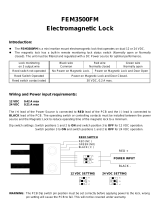
On LSS option, the magnetic lock has a built-in reed switch for remote lock monitoring status (Open
r o Closed) on three output wires:
RED wire (Normally closed);
Green wire (Normally open)
Black wire (Common)
Reed Switch not Operated- No Power on magnetic lock.
Power on magnetic lock and door Open.
Reed Switch Operated- Power on magnetic lock and door Closed.
The Reed Switch contacts are rated at 24 volts at 0.2 ampere maximum.
The FEM 5000S/ F/ G
is critical to secure the magnetic lock firmly on the door frame to avoid
loosening screws and causing possible injuries.
The armature plate must remain movable to allow surface alignment with the magnet face. The
magnetic lock will lose holding force without fl
oating alignment.
Trimming rubber washers will adversely effect the operation of magnetic lock.
BROWN
PURPLE
BLUE
YELLOW
+
-
BROWN
PURPLE
BLUE
YELLOW
+
-
12 VDC/ 0.48 A 24 VDC/ 0.24 A
REED SWITCH SENSOR
RED
BLACK
GREEN
NC
C
NO
Important Safety Requirements
1. Apply thread-locker glue (i.g. Loctite) to the thread of the Armature-Plate-Fixing Screw (Allen-Screw) to
prevent from becoming loose.
2. Locks should be inspected at regular intervals to ascertain the safety functionality in conjunction with the
door environment.
3. The supplied Allen screws cater for maximum door-thickness of 45mm.
LINK
LINK
LINK
The FEM 5000S/ F/ G electromagnetic is specifically designed for exterier application with the lock
casing made of stainless steel.
FEM 5000S is side mounted with the wire exit opposite to the mount,FEM 5000F is face mounted
with the wire exit opposite to the mount. The FEM 5000G can be either side or front mounted with
wire exit on the head end. Voltage spike suppressor are embedded inside the electromagnetic lock
to compensite unwanted high voltage spikes.
The lock has no residual magnetism and opens instantly upon power isolation.
The electromagnetic lock should always be mounted on the sucure side of the door.
1 V1.0 2013

Trouble Shooting
Problem Possible Cause Solution
Door will not lock No DC voltage to lock.
Check power supply and wiring to
magnetic lock.
Ensure mating surfaces are clean and in
proper alignment and the armature plate
floats freely.
Correct to desired voltage setting and
power input requirement
Bad physical contact between
armature plate and face of magnet.
Low voltage or wrong voltage setting
Reduced holding force
Reed Switch Status is
incorrect
Maintenance
Contacting surface of the electro-magnet and Armature plate must be kept free of contaminating
materials. Surfaces should be cleaned periodically with a non-abrasive cleaner. Do not spray the
electro-magnet and armature plate surface with any chemicals such as lacquer, etc. This will create
problems with the release of the armature plate from the magnetic lock and can cause serious safety
problems.
Sample of Mounting Procedure
1.Sliding Door Installation
FEM 5000F
FEM 5000S
FEM 5000G
One way security dome nut
This backet is
not part of product
offering.
Has to be custom
built on site.
2 V1.0 2013

3 V1.0 2013
/


