Page is loading ...

HARDWARE KITS:
NO. DESCRIPTION QTY
1 M5*8 C’SINK SCREWS 9
2 ST3.5*25 C’SINK SCREWS 5
3 ST5*32 C’SINK SCREWS 5
4 LOCK BODY BRACKETS 2
5 M4*9.5 C SINKSCREW 9
6 FLAT WASHERS 5
7 ARMATURE PLATE BRACKETS 2
-8-
FSH 2500
INSTALLATION MANUAL
ANOTHER QUALITY PRODUCT
-1-
V
.101123
V
2mob

GENERAL INFORMATION
1. Before mounting an electromagnet, please make sure that all the security
requirements are being respected.
2. The purpose of the electromagnets being the securing of an access, they
have to be mounted in such a way that they resist shocks, both from the door
closing as well as from attempted break-ins.
3. An electromagnet should always be mounted on the secured side of the
access.
Part list:
1 x Lock Body 1 x Armature Plate
1 x PCB Set 1 x LED
1 x Hardware Kits 1 x Manual
Ratings:
Holding Force: 250Kg
Relay: 1 A/ 24 VDC
Input power: Accept power in the range of 12 ~ 24 VDC
Power Consumption:
Voltage
Rush Current Holding Current
12 VDC 1.2 A 0.2 A
24 VDC 0.6 A 0.1 A
-2-
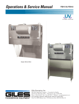
WIRING DETAILS
Typical Wiring
NOTE: Warranty void if the included PCB is not installed in accordance with
FSH instructions.
All wires
(DSS, LSS & Power) between the lock body and the PCB
Board must be connected
, whether the function will be used or not.
DIP SWITCH
LSS
OUTPUT
GND
NO
COM
NC
12~24 VDC
ADJUSTABLE
TIME DELAY
BLUE
WHITE
YELLOW
BLUE
BROWN
WHITE
YELLOW
BLACK
RED
BROWN
LED
YELLOW
YELLOW
WHITE
WHITE
BLACK
RED
ADJUSTABLE TIME DELAY
LED INDICATOR
MAGNETIC LOCK
POWER TO LOCK
LSS - LOCK STATUS SENSOR
DSS - DOOR STATUS SENSOR
ON
OFF
1
23
ON
OFF
1
23
BLUE
BROWN
Adjustable Time Delay, LED, Lock Status Sensor & Retry.
1. The adjustable time delay can be set to delay unlock time from 0 to 6 seconds.
ON
OFF
1
2
3
ON
OFF
1
2
3
ON
OFF
1
2
3
ON
OFF
1
2
3
ON
OFF
1
2
3
ON
OFF
1
2
3
0 sec
1 sec
2 sec 3 sec 4 sec 5 sec 6 sec
Delay time
Dip switch
position
ON
OFF
1
2
3
The LED’s indicator indicates lock status.
LED off LED blinking LED on
Door open Locked unsuccessfully Locked successfully
2. The Lock Status Sensor outputs C, NC & NO indicates door locked or unlocked. C & NC
conducted – Unlocked. C & NO conducted – Locked.
3. The door will try a further 4 locking attempts if the door locks unsuccessfully.
-7-

TYPICAL MOUNTING ON WOODEN DOOR
TYPICAL MOUNTING ON ALUMINUM ,
METALLIC OR PVC DOOR
Mounting on aluminum or PVC doorMounting on metallic door
-4-
DIMENSION OF MOUNTING
Mounting on Metallic, Aluminum or PVC Door (Lock Body &
Armature Plate)
C
A
B
166
A= 32mm (Lock Body) A= 27mm (Armature Plate)
B= 19mm (Lock Body) B= 14mm (Armature Plate)
C= Ф5.5XФ10X90° (Lock Body) C= Ф4.5XФ8X90° (Armature Plate)
Mounting on Wooden Door (Lock Body)
Wire Access:10
Drill for ST 5.0 Screw
3 X4PCS.
Wire Access
-5-

Mounting on Wooden Door (Armature Plate)
Drill for ST. 4.0
Screw 2X4 pcs
ADJUST AFTER MOUNTING
After mounting, adjust the adjusting screws to make sure the gap is 3mm as
drawing above.
-6-
SET-UP OF FSH 2500
TYPICAL MOUNTING
-3-
3
m
m
/