AIRTRONICS M12 User manual
- Category
- Remote controlled toys
- Type
- User manual

1
TR

2
TR
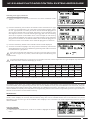
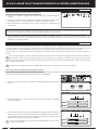
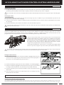
Additional Airtronics 2.4GHz FH2, FH3, FH4 and FH4T surface receivers* can be purchased and paired with the M12
transmitter. Due to differences in the implementation of 2.4GHz technology among different manufacturers, only Airtronics
brand 2.4GHz surface receivers are compatible with your radio control system. Telemetry functions are available only when used
with Telemetry-capable receivers (available separately). Visit your local Airtronics dealer or our website at http://www.airtronics.net
for more information.
The packaging of your radio control system has been specially designed for the safe transportation and storage of the system's
components. After unpacking your radio control system, do not discard the packaging materials. Save the packaging materials
for future use if you ever need to send your radio control system to us for service or to store your radio control system if you don't
plan on using it for an extended period of time.
*Not all Features are Supported by all Types of Receivers. Some Features Limited by Receiver Type
Introduction..........................................................................................................................................................................................................................................Page 2
Packaging.............................................................................................................................................................................................................................................Page 2
Service and Support .......................................................................................................................................................................................................................Page 3
Safety ......................................................................................................................................................................................................................................................Page 3
FCC Compliance Statement .......................................................................................................................................................................................................Page 3
2.4GHz Frequency Band Precautions ....................................................................................................................................................................................Page 4
Transmitter Precautions ................................................................................................................................................................................................................Page 4
Receiver Precautions ......................................................................................................................................................................................................................Page 4
Servo Connectors .............................................................................................................................................................................................................................Page 4
System Features ...............................................................................................................................................................................................................................Page 5
What's Included .................................................................................................................................................................................................................................Page 5
System Specifications ....................................................................................................................................................................................................................Page 5
Transmitter Overview Diagrams ...............................................................................................................................................................................................Page 6
Receiver Overview Diagram, Connections and Mounting ..........................................................................................................................................Page 8
Transmitter and Receiver Overview Diagram Descriptions ........................................................................................................................................Page 8
Transmitter Warning Alarms and LED Condition Indicators.....................................................................................................................................Page 10
Transmitter Battery Options ......................................................................................................................................................................................................Page 11
Alkaline Battery Installation ........................................................................................................................................................................................................Page 11
Transmitter Battery Charging Options .................................................................................................................................................................................Page 11
Warnings if Using a Li-Po or Li-Fe Battery Pack ..............................................................................................................................................................Page 11
Steering Wheel and Throttle Trigger Spring Tension Adjustment .........................................................................................................................Page 12
Optional Steering Wheel Spring Installation .....................................................................................................................................................................Page 12
Steering Wheel Travel Adjustment ........................................................................................................................................................................................Page 12
Optional Steering Wheel Installation ....................................................................................................................................................................................Page 13
Optional Grip Installation ............................................................................................................................................................................................................Page 13
Throttle Trigger Angle Adjustment .........................................................................................................................................................................................Page 13
Wrist Strap Anchor Installation ................................................................................................................................................................................................Page 13
Throttle Trigger Position Adjustment ....................................................................................................................................................................................Page 14
Optional Steering Wheel Offset Plate Installation ..........................................................................................................................................................Page 14
Optional Steering Wheel Angle Plate Installation...........................................................................................................................................................Page 15
Driving Position Adjustment ......................................................................................................................................................................................................Page 16
Programming Keys Overview and Functions...................................................................................................................................................................Page 17
Display Screens Overview .........................................................................................................................................................................................................Page 17
Main Menu Structure Overview...............................................................................................................................................................................................Page 19
Main Menus Overview .................................................................................................................................................................................................................Page 20
Telemetry Screen Overview ......................................................................................................................................................................................................Page 21
Transmitter and Receiver Binding..........................................................................................................................................................................................Page 23
System Menu Overview ..............................................................................................................................................................................................................Page 24
Includes System Programming Menu Contents ........................................................................................................................................Page 24
Setup Menu Overview ..................................................................................................................................................................................................................Page 61
Includes System Programming Menu Contents ........................................................................................................................................Page 61
Racing Menu Overview ...............................................................................................................................................................................................................Page 74
Includes System Programming Menu Contents ........................................................................................................................................Page 74
Custom Menu Overview .............................................................................................................................................................................................................Page 94
Includes System Programming Menu Contents ........................................................................................................................................Page 94
Telemetry Connections and Mounting ................................................................................................................................................................................Page 96
Troubleshooting Guide ................................................................................................................................................................................................................Page 97
Racing Mode Functions by Car Type Table ......................................................................................................................................................................Page 99
Trim Switch Functions Table .................................................................................................................................................................................................Page 100
Glossary of Terms ........................................................................................................................................................................................................................Page 101
Index ...................................................................................................................................................................................................................................................Page 106

3
TR
This is a high-output, full-range radio control system that should well exceed the range needed for any surface Model. For safety,
the user should perform a range test at the area of operation to ensure that the radio control system has complete control of the
Model at the farthest reaches of the operational area. Rather than operating the Model, we recommend that the user enlist the
help of a fellow modeler to walk the Model to the farthest reaches of the track (or for boats, to walk the shore line well in excess
of the operational distance of the boat), then test for proper operation.
• Be certain to read this User's Guide in its entirety.
• 'Safety First' for yourself, others and your equipment.
• Observe all the rules of the field, track or lake where you operate your radio control equipment.
• If at any time during the operation of your Model, should you feel or observe erratic operation or abnormality, end your operation
as quickly and safely as possible. DO NOT operate your Model again until you are certain the problem has been corrected.
TAKE NO CHANCES.
• Your Model can cause serious damage or injury. Please use caution and courtesy at all times.
• Do not expose the radio control system to water or excessive moisture.
• Waterproof the receiver and servos by placing them in a water-tight radio box when operating R/C Model boats.
• If you have little to no experience operating R/C Models, we recommend you seek the assistance of an experienced modeler
or your local hobby shop for guidance.
• The Low Voltage Alert alarm will sound when the transmitter battery voltage drops to the default threshold of 4.6 volts. If this
occurs, stop using the transmitter as soon as is safely possible, then replace or recharge the transmitter batteries.
This radio control system operates on the 2.4GHz frequency band. The 2.4GHz connection is determined by the transmitter
and receiver pair. Unlike ordinary crystal-based systems, your Model can be used without frequency control.
This equipment has been tested and found to comply with the limits for a Class B digital device, pursuant to Part 15 of the FCC
Rules. These limits are designed to provide reasonable protection against harmful interference in a residential installation. This
equipment generates, uses, and can radiate radio frequency energy and, if not installed and used in accordance with the operating
instructions, may cause harmful interference to radio communications. However, there is no guarantee that interference will not
occur in a particular installation.
If this equipment does cause harmful interference to radio or television reception, which can be determined by turning the
equipment OFF and ON, the user is encouraged to try to correct the interference by one or more of the following measures:
• Reorient or relocate the receiving antenna.
• Increase the separation between the equipment and the receiver.
• Connect the equipment into an outlet on a circuit different from that to which the receiver is connected.
• Consult the dealer or an experienced technician for help.
This device complies with Part 15 of the FCC Rules and with RSS-210 of Industry Canada. Operation is subject to the following
two conditions:
1) This device may not cause harmful interference, and....
2) This device must accept any interference received, including interference that may cause undesired operation.
Changes or modifications made to this equipment not expressly approved by Airtronics may void the FCC authorization to
operate this equipment.
RF Exposure Statement:
This transmitter has been tested and meets the FCC RF exposure guidelines when used with the Airtronics accessories supplied
or designated for this product, and provided at least 20cm separation between the antenna the user's body is maintained. Use of
other accessories may not ensure compliance with FCC RF exposure guidelines.
If you have any questions or concerns, we're here to help. If you encounter a problem with your radio control system, first check
the
Troubleshooting Guide
section on pages 97 ~98. If you require further help, please contact us directly.
In North America Only:
Global Services
18480 Bandilier Circle
Fountain Valley, CA 92708
Telephone: 1-714-963-0329
Fax: 1-714-964-6236
Email: [email protected]
If you made your purchase outside of North America, please contact your regional Airtronics/Sanwa agent for service and support.

4
TR
• The 2.4GHz frequency band may be used by other devices, or other devices in the immediate area may cause interference on
the same frequency band. Always before use, conduct a bench test to ensure that the servos operate properly. Also, conduct
checks with the transmitter as distant as possible from your Model.
• The response speed of the receiver can be affected if used where multiple 2.4GHz transmitters are being used, therefore,
carefully check the area before use. If response seems slow during use, stop your Model immediately and discontinue use.
• If the 2.4GHz frequency band is saturated (too many transmitters turned ON at once), as a safety precaution, the transmitter
and receiver may not Bind. This ensures that your radio control system does not get hit by interference. Once the frequencies
have been cleared, or the saturation level has dropped, your transmitter and receiver should Bind without any problems.
• To prevent possible damage to your servos or a runaway Model, turn the transmitter ON first,
then turn the receiver ON. After running your Model, turn the receiver OFF first, then turn the
transmitter OFF.
• Before use, double-check that the transmitter and receiver batteries have sufficient
power.
• The transmitter antenna is mounted internally and is located in the vertical back portion of the carrying handle. Do
NOT cover the carrying handle in any way during use! Doing so can block the RF signal, resulting in loss of control
of your Model.
• During use, hold the transmitter so that its orientated as close to vertical as possible at all times. This provides the best RF
signal between the transmitter and the receiver. Try not to ever 'follow' your Model with the transmitter, as
this can result in a weakened RF signal.
• Do not expose the transmitter or any other components to excessive heat, moisture,
fuel, exhaust residue, etc.
• If the outer case becomes dirty, it can be cleaned with a soft dry cloth. If the outer case becomes
soiled, it can be cleaned with a damp cloth and liquid detergent.
• Do not use any solvents to clean the outer case. Solvents will damage the finish.
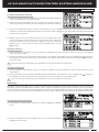
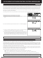
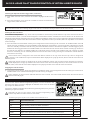
The receiver uses Airtronics 'Z' connectors, which are electronically compatible with the servos of other radio control system
manufacturers. The connectors are rugged, but should be handled with care.
When unplugging the servo connector, don't pull on the servo wire itself. This could result in damage to the servo wire pins
in the plastic plug. Always grasp the plastic connector itself.
- = Negative (Black)
+ = Positive (Red)
S = Signal (Blue)
If using another brand of servo, double-check the polarity
of the servo connector prior to plugging it into the receiver.
• The antenna consists of a coaxial cable and a reception wire (the thin tip at the end of the coaxial cable). When you mount the
antenna, do not bend the reception wire. Reception performance decreases if the reception wire is bent.
• The antenna is delicate, therefore, handle with care. Do not pull on the antenna with force. Do not
cut or extend the antenna.
• The coaxial cable (the thicker portion of the antenna) can be bent into gentle curves, however, do
not bend the coaxial cable acutely, or repeatedly bend it, or the antenna core can be damaged.
• The antenna should be installed into a vertical plastic tube per your particular Model's assembly instructions. Keep the receiver
antenna as far away from the motor, battery and ESC as possible.
• There is a danger of runaway operation if connectors shake loose during use. Make sure that the receiver, servo(s) and switch
connectors are securely fitted.
• The receiver is susceptible to vibration, shock and moisture. Take appropriate measures to protect against vibration and
moisture. Failure to take appropriate measures could result in runaway operation or damage to the receiver. We suggest
wrapping the receiver in shock-absorbing foam or securing it with double-sided foam tape when installing it into your Model.
• When routing the antenna, avoid contact with any carbon or metal chassis components. Contact between metal or carbon
parts can result in electrical noise, which can adversely effect receiver performance and possibly result in runaway operation
and result in damage to your Model.
• With electric-powered Models, be sure to fit any brushed motors with a noise suppression capacitor. Without a noise suppression
capacitor, excessive electrical noise generation can cause runaway operation and result in damage to your Model.

5
TR
Transmitter:
• Model: M12
• Output Power: 100mW
• Nominal Input Voltage: 4.8v ~ 7.4v
• Operating Voltage Range: 4.0v ~ 9.0v
• Dry Weight: 20.8oz (590g)
• Frequency: 2.4GHz FHSS
• Modulation Type: FH2, FH3, FH3F, FH4T, FH4FT
Receiver:
• Model: RX-471 Super Response
• Nominal Input Voltage: 4.8v ~ 7.4v
• Weight: 0.23oz (6.6gr)
• Dimensions: 1.18 x 0.91 x 0.55in (30.0 x 23.3 x 14.0mm)
• Frequency: 2.4GHz FH3/FH4 Selectable Via Transmitter
• Fail Safe Support: Yes (All Channels)
• Battery Voltage Fail Safe Limit: 3.5 ~ 5.0v (FH3) / 3.5 ~ 7.4v (FH4)
• 4-Channel 2.4GHz FH4T Digital High-Response Telemetry System with Advanced Programming
• Large LCD Screen Features STATUS screen, ASSIGN screen and TELEMETRY screen*
• High-Power FH4T Technology Provides the Best Reception and Connectivity, Giving Racers Added Assurance
• 4-Cell Dry Battery Holder for Lighter Weight - Also Accepts Optional Ni-Cd/Ni-MH Batteries or 2S Li-Po/Li-Fe Battery Pack
• Includes RX-471 2.4GHz FH4 Super Response Receiver
• 50 Model Memory
• Direct Model Select Up to 3 Models
• Adjustable Steering and Throttle Channel Response Time
• 10 Car Type Templates Including 3 Crawler Setups
• User-Selectable Start-Up Screen
• PC-Link Allows PC-Connectivity Using Mini USB Cable
• Receiver Safety Link
• Large, Easy-to-Reads LCD with Smooth Scrolling
• Telemetry Logging and Servo Monitor
• Five Racing Modes Allow Setup Changes on the Fly While Driving
• Model Select, Naming, Copy, Clear and Sort
• Selectable Modulation Type
• Programmable Push-Button Switches, Trim Switches, Lever and Dial
• Configurable Vibration Alarms and Timers
• User Naming
• Servo Reversing
• Steering, Throttle and Brake Dual Rate
• End Point Adjustment
• Exponential, ARC and Curve Adjustments
• Servo Speed Adjustment
• Anti-Lock Braking
• Throttle Offset
• Throttle Hold
• Lap Timer and Two Interval Timers
• Large, Easy-to-Read Lap Timer Display
• Two Compensation Mixers
• Channel Set Menu
• Normal, SSR and SHR Servo Modes
• Center or Parallel Trim Types
• Programmable Fail Safe
• Receiver Battery Voltage Fail Safe
• Digital Trims
• Servo Sub-Trim
• Variable Rate Adjustment
• Selectable Throttle Bias
• Adjustable Key Volume and Tone
• Programmable Low Voltage Alert and Limit Alarms
• Separate Display Button
• Inactivity and Over Voltage Alarms
• Digital Battery Voltage Monitor
• Adjust for Right-Handed or Left-Handed Use
*Requires Airtronics RX-461, RX-462 or Other Airtronics FH4T Telemetry Receiver, Available Separately
• M12 FH4T Digital High-Response Telemetry Transmitter
• RX-471 Super Response Receiver
• On/Off Switch
• Optional Grips (Large and Small)
• Optional Larger Diameter Steering Wheel
• Optional Steering Wheel Angle Plates (Right and Left)
• Optional Steering Wheel Offset Plate
• Optional Steering Wheel Springs (Soft and Hard)
• Optional Throttle Trigger Angle Brackets (Thin and Thick)
• Receiver Dust Boot Covers
• Transmitter Wrist Strap Mount
In addition to the transmitter, receiver and on/off switch, a number of optional items are included to customize the transmitter to
your exact liking. This ensures the best comfort and feel during many hours of use.

6
TR
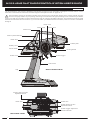
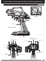
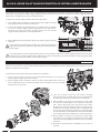
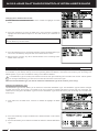
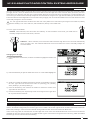
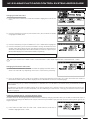
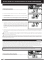
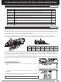
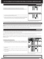
Grip
Antenna (Inside Handle)
Throttle Trigger
Power Switch
Auxiliary Lever
Steering Wheel
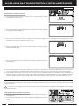
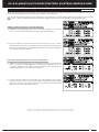
Use the diagrams in this section to familiarize yourself with the layout of your transmitter. Descriptions of these features can be
found in the
Transmitter and Receiver Overview Diagram Descriptions
section on pages 8 ~ 9.
The transmitter antenna is mounted internally and is located in the vertical back portion of the carrying handle. Do NOT
cover the carrying handle in any way during use! Doing so can block the RF signal, resulting in loss of control of your Model.
During use, hold the transmitter so that its orientated as close to vertical as possible at all times. This provides the best RF signal
between the transmitter and the receiver. Try not to ever 'follow' your Model with the transmitter, as this can result in a weakened
RF signal.
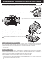
Switch Sw3
Switch Trm5
Switch Sw1
Auxiliary Dial
Switch Trm3
Switch Trm1
Switch Trm2
Switch Trm4
Switch Sw2Switch Sw2
Steering Spring Tension
Adjustment Screw
Throttle Trigger Adjustment
Position Indicator
Throttle Spring Tension
Adjustment Screw

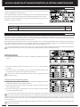
7
TR
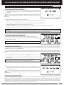
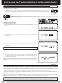
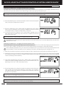
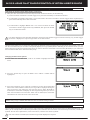
Charge Jack
Switch Sw3*
Switch Trm5*
Battery Compartment
PC-Link Input
(Under Cover)
Display Key
LCD Screen
LED1 LED2
Racing Mode LED
Back Key
Push-Button Rotary Dial
(Up/Down/Enter Key)
Select Switch
Throttle Trigger Position
Adjustment Screw
Wrist Strap Anchor Slot
*For Left-Handed Use
Wrist Strap
Anchor Slot*

8
TR
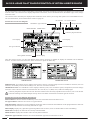
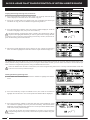
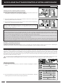
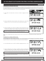
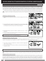
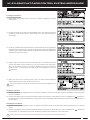
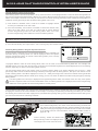
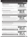
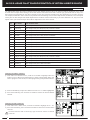
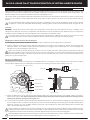
Use the diagrams in this section to make receiver connections and to familiarize yourself with the RX-471 4-Channel 2.4GHz FH4
Super Response receiver included with your M12 radio control system. Descriptions of the features can be found in the
Transmitter
and Receiver Features Descriptions
section below and on the next page.
The receiver's Nominal Input Voltage is 4.8 ~ 7.4 volts. A 2 cell Li-Po or Li-Fe battery pack can be used to power the receiver without
the use of a voltage regulator. In addition, this allows you to take advantage of the Higher torque and speed provided by using
7.4 volt digital servos.
Use a 2 cell Li-Po or Li-Fe battery pack ONLY if your servos are rated to handle the Higher voltage.
• We suggest Binding the transmitter and receiver and making all receiver connections to check for correct
operation prior to mounting the receiver in your Model.
• The receiver should be mounted as far away from any electrical components as possible. When routing the
antenna, avoid contact with any carbon or metal chassis components. Contact between metal or carbon
parts can result in electrical noise, which can adversely effect receiver performance and possibly result in
runaway operation and result in damage to your Model.
• Route the receiver antenna up through a plastic tube so that it is in the vertical position. Do not bend the
reception wire. Reception performance decreases if the reception wire is bent. Do not pull on the antenna with force. Do not
cut or extend the antenna. The coaxial cable can be bent into gentle curves, however, do not bend the coaxial cable acutely,
or repeatedly bend it, or the antenna core can be damaged.
• To protect the receiver from vibration and other damage, we recommend wrapping the receiver in shock absorbing foam or
using double-sided foam tape when installing it in your Model.
As a safety precaution, set your Model on a stand so the wheels are off the ground before turning on your radio control
system or connecting your motor for the first time.
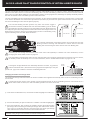
Bind Button
= Signal
= Positive
= Negative
Bind LED
Coaxial Cable
Antenna
Reception Wire
Steering
Channel 1
Throttle
Channel 2
Auxiliary 1
Channel 3
Auxiliary 2
Channel 4
On/Off Switch
'AA' Dry Cell Battery Holder,
4.8v ~ 7.4v Ni-Cd/Ni-MH Battery Pack or
2S Li-Po/Li-Fe Battery Pack
On/Off Switch
To Battery
To Motor
ESC
Throttle
Channel 2
Glow/Gas
Setup
ESC
Setup
Antenna Tube
Coaxial Cable
Antenna
Reception Wire
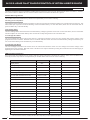
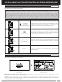
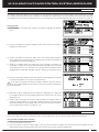
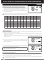
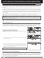
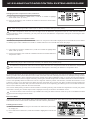
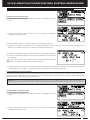
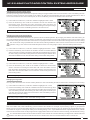
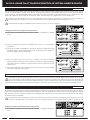
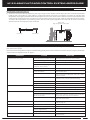
Bind LED Condition Indicator:
The Bind LED on the receiver can be used to determine receiver condition at a glance. The Bind LED will alert you to various
receiver conditions, as shown in the table below.
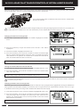
Antenna: Transmits the signal from the transmitter to the receiver in the Model.
Antenna Reception Wire: The portion of the receiver antenna that receives the transmitter signal. The Antenna Reception Wire
should never be bent or it could be damaged and limit the range of your Model.
Auxiliary Dial: The Auxiliary Dial can rotate 360º and is programmable to perform a different function depending on what function
is Assigned to it. In the default configuration, it controls Auxiliary 1 High and Low servo travel.
Auxiliary Lever: The Auxiliary Lever is programmable and will perform a different function depending on what function is Assigned
to it. In the default configuration, it controls Auxiliary 2 High and Low servo travel.
Blue
Blue
Red & Blue
Red
Receiving RF Signal
Binding Operation
Receiver Battery Fail Safe Activates
No RF Signal After Receiver Battery Fail Safe Activates
LED COLOR
RECEIVER STATUS
LED CONDITION
ON
Slow Flash/Fast Flash
Flash
ON

9
TR
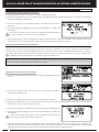
Back Key: Pressing the BACK key returns the Programming Cursor to the previous menu. Press the BACK key repeatedly to return
to the STATUS screen.
Battery Compartment: Houses the four 'AA' Alkaline cells that power the transmitter. Alternatively, the transmitter can be powered
using four 'AA' Ni-Cd or Ni-MH rechargeable batteries or a 2S Li-Po or Li-Fe battery pack.
Bind Button: Used in the process of Binding the transmitter and receiver.
Bind LED: Displays the current operating status of the receiver.
Charge Jack: Used for onboard charging of optional Ni-Cd or Ni-MH batteries. Do not attempt to charge Alkaline batteries. Only
the recommended Airtronics 110v AC charger should be used through the Charge Jack. If using an after-market Peak-Detection
charger or other type of fast charger, the batteries should be removed from the transmitter to avoid damage to the transmitter
circuitry and/or your batteries. Do not attempt to charge a Li-Po or Li-Fe battery pack through the Charge Jack.
Coaxial Cable: The portion of the receiver antenna that extends the Antenna Reception Wire. The Coaxial Cable can be bent into
gentle curves, however, do not bend it acutely, or repeatedly bend it or the antenna core can be damaged.
Display Key: Turns the transmitter's LCD Screen ON without actually turning the transmitter ON. This allows you to check and/or
change programming options without actually turning the transmitter ON. To turn only the LCD Screen ON, press and HOLD the
DISPLAY key for approximately 3 seconds. To turn the LCD Screen OFF, press the DISPLAY key once.
Grip: The Grip is molded from rubber in an ergonomic shape for increased comfort, control and feel.
LED1: Displays the current RF signal output status of the transmitter. When illuminated, an RF signal is being transmitted. When
extinguished, no RF signal is being transmitted. In addition, LED1 is used to indicate various transmitter conditions.
LED2: Displays the current status of the Telemetry connection. When illuminated, no Telemetry connection is present. When
extinguished, the Telemetry connection is Active. In addition, LED2 is used to indicate various transmitter conditions.
LCD Screen: The heart of the programming and display features of the transmitter. All programming and transmitter display
functions are shown on the LCD Screen. The M12 features a large, backlit LCD Screen with smooth scrolling.
PC-Link Input: When used with an USB cable with a Mini USB connector (available separately), the PC-Link Input allows you
to save Telemetry Data Logs and Model Programming Data to your PC. In addition, it also allows you to load saved Model
Programming Data from your PC and update the M12's software version.
Power Switch: Turns the transmitter ON and OFF.
Push-Button Rotary Dial: The Push-Button Rotary Dial (also referred to as the UP key, DOWN key and ENTER key) is used along
with the BACK key and the SELECT switch to facilitate transmitter programming. It allows you to quickly and easily navigate the
various Programming Menus and switch between the STATUS screen, ASSIGN screen and TELEMETRY screen.
Push-Button Switches: The transmitter features three Push-Button Switches in different locations (Sw1, Sw2 and Sw3). Each
Push-Button Switch is programmable and will perform a different function depending on what function is Assigned to it. For
example, Sw1 can be used to operate a reverse servo in a gas- or glow-powered Model and Sw3 can be used to toggle Anti-Lock
Braking ON and OFF. Sw2 is a Rocker Switch that can be pressed from either the Front or the Back.
Racing Mode LED: Displays the currently Active Racing Mode. The color of the LED will vary depending on which of the Five
Racing Modes is Active. When extinguished, Racing Mode is Inhibited.
Select Switch: Used along with the Push-Button Rotary Dial and the BACK key to facilitate transmitter programming. Use the
SELECT switch to scroll through the STATUS screen's main menus, scroll through the TELEMETRY pages and make selections
in many of the Programming Menus.
Steering Spring Tension Adjustment Screw: Used to adjust the spring tension of the Steering Wheel to best suit the feel of the
user. Turning the Steering Spring Tension Adjustment Screw clockwise increases Steering Wheel spring tension and turning the
Steering Spring Tension Adjustment Screw counter-clockwise decreases Steering Wheel spring tension.
Steering Wheel: Proportionally operates the Model's Right and Left Steering control. The Steering Wheel features a foam grip for
increased comfort, control and feel. The Steering Wheel's position, angle and spring tension can all be adjusted.
Throttle Trigger: Controls the speed of the Model, both forward and backward, or the Model's Brake. The Throttle Trigger position,
angle and spring tension can all be adjusted.
Throttle Spring Tension Adjustment Screw: Used to adjust the spring tension of the Throttle Trigger to best suit the feel of the
user. Turning the Throttle Spring Tension Adjustment Screw clockwise increases Throttle Trigger spring tension and turning the
Throttle Spring Tension Adjustment Screw counter-clockwise decreases Throttle Trigger spring tension.
Throttle Trigger Adjustment Position Indicator: Indicates the current position of the Throttle Trigger. As the Throttle Trigger
position is adjusted forward or backward, the Throttle Trigger Adjustment Position Indicator will move forward or backward.
Trim Switches: The transmitter features five separate Trim Switches - four positioned around the Steering Wheel (Trm1, Trm2,
Trm3 and Trm4 and one positioned below the Auxiliary Lever (Trm5). Each Trim Switch is programmable and will perform a different
function depending on what function is Assigned to it. For example, Trm1 and Trm2 can be used to adjust Steering and Throttle
Trim and Trm4 and Trm5 can be used to adjust Dual Rate and Steering EPA.
Wrist Strap Anchor Slot: Used to attach the wrist strap anchor to the transmitter.

10
TR
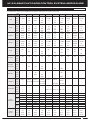
The M12 is equipped with several different Audible Warning Alarms to warn you of an abnormal transmitter condition. In addition,
LED1, LED2 and the R-MODE LED are used to indicate various transmitter conditions at a glance.
Inactivity (Power ON) Alarm:
The Inactivity Alarm will sound if the transmitter is Left on for a period of 10 minutes without any control input from the user. This
alarm alerts you to prevent unwanted draining of the transmitter battery. To clear this alarm, either turn the transmitter OFF or
press the BACK key or the ENTER key.
Over Voltage Alarm:
The Over Voltage Alarm will sound if the transmitter battery voltage is greater than 9.6 volts. To clear this alarm, turn the transmitter
OFF and replace the transmitter battery with one that when fully charged does not exceed 9.6 volts.
Low Voltage Alert Alarm:
The Low Voltage Alert alarm will sound when the transmitter batteries reach the Low Voltage Alert alarm voltage value
programmed in the SYSTEM - BATTERY menu. The alarm will sound each time the transmitter battery voltage decreases by 0.1
volt. To clear this alarm, press the BACK key or the ENTER key.
Low Voltage Limit Alarm:
The Low Voltage Limit alarm will sound when the transmitter batteries reach the Low Voltage Limit alarm voltage value
programmed in the SYSTEM - BATTERY menu. This alarm can only be cleared by turning the transmitter OFF and recharging or
replacing the transmitter batteries.
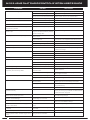
LED1, LED2 and the R-MODE LED are used to indicate various transmitter conditions at a glance. Some of the conditions indi-
cated by the LEDs may also be accompanied by an audible alarm and/or and on-screen warning.
------
------
------
------
------
------
------
------
------
------
------
------
------
OFF
OFF
OFF
Green
Magenta
Cyan
Yellow
White
OFF
------
------
------
------
------
------
0.1 Sec. Flash
0.1 Sec. Flash
OFF
ON
0.35 Sec. Flash
0.05 Sec. Flash
0.05 Sec. Flash
1 Sec. Flash
1 Sec. Flash
------
------
------
------
------
------
------
OFF
ON
0.1 Sec. Flash
0.5 Sec. Flash
0.35 Sec. Flash
0.05 Sec. Flash
------
------
------
------
------
------
------
1 Sec. Flash
------
------
------
------
------
------
------
------
TRANSMITTER STATUS
LED1 CONDITION
R-MODE LED CONDITION
Display Mode
RF Output Signal
Throttle Offset Function Active
Telemetry Logger Function Active
RF Binding - Sending Bind Code
PC-Link USB Send/Receive Active
Inactivity Alarm Active
Telemetry Alarm Active
Telemetry Connection Active
No Telemetry Connection
Low Voltage Alert Alarm Active
Low Voltage Limit Alarm Active
Over Voltage Alarm Active
Transmitter Error
Programming Data/Update Error
Unrecoverable Update Error
Racing Mode 1 Active
Racing Mode 2 Active
Racing Mode 3 Active
Racing Mode 4 Active
Racing Mode 5 Active
Racing Mode Function Inhibited
LED2 CONDITION
------ Indicates HOLD Condition. LED May Be ON or OFF Depending on Other Specific Conditions
The audible alarms listed below may also be accompanied by an on-screen warning.

11
TR
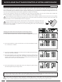
3) Slide the battery cover back onto the transmitter and push it firmly until it 'clicks' closed.
When installing the batteries, remove the battery holder and double-check that the battery holder is plugged in. If it isn't, plug
the connector on the battery holder into the matching connector in the transmitter.
1) Remove the battery cover from the bottom of the transmitter by pushing firmly on the battery cover in the direction of the arrow.
The M12 transmitter's Operating Voltage Range is 4.0 ~ 9.6 volts. This allows you to use several different battery options (not
included), depending on your preference.
Alkaline - In the default configuration, the transmitter is designed to be powered using four 'AA' Alkaline batteries. This results
in a transmitter that is lightweight and well-balanced for unmatched comfort.
Ni-Cd/Ni-MH - Rechargeable Ni-Cd or Ni-MH batteries of desired capacity can be used in place of the Alkaline batteries. Using
rechargeable Ni-Cd or Ni-MH batteries is more convenient and cheaper in the long run. The Higher capacity batteries will also
provide longer usage time than most Alkaline batteries.
Li-Po or Li-Fe - A 2 cell Li-Po or Li-Fe battery pack can be used to power the transmitter. These battery packs are popular due
to their light weight and high capacity for long usage time between charges.
Transmitter power output, range and speed are the same, regardless of the battery type used. If using a Li-Po or Li-Fe battery
pack, please read the
Warnings if Using a Li-Po or Li-Fe Battery Pack
section below.
• Use ONLY a 2 Cell Li-Po or Li-Fe battery pack of desired capacity.
• Do NOT charge your Li-Po or Li-Fe battery pack through the Charge Jack. The battery pack MUST be removed from the
transmitter prior to charging or the transmitter could be damaged. For more information, see the WARNING in the
Transmitter
Battery Charging Options
section above.
• Use a charger specifically designed to charge Li-Po or Li-Fe battery packs.
• When changing the connector on your battery pack to match the battery connector in the transmitter,
please observe correct polarity. Connecting with reverse polarity will damage the transmitter.
• Observe all safety precautions provided with your Li-Po or Li-Fe battery pack.
• Damage to the transmitter caused by improper use, wrong battery type, incorrect voltage, reverse polarity or charging
through the Charge Jack will not be covered under warranty!
The transmitter has a Nominal Input Voltage range of 4.8 ~ 7.4 volts. DO NOT USE A 3 CELL Li-Po or Li-Fe battery pack or
the transmitter will be damaged!
- = Negative (Black)
+ = Positive (Red)
The M12 transmitter features a Charge Jack that can be used with the Airtronics 95034 Dual Output charger (available separately)
to charge the optional Ni-Cd or Ni-MH batteries. This allows you to charge these batteries without removing them from the
transmitter. A Charge Jack is located on the Left side of the transmitter. For more information, see the
Transmitter Overview
Diagrams
section on page 7.
WARNING: Do NOT attempt to recharge Alkaline batteries. Only Ni-Cd or Ni-MH batteries should be charged through the
transmitter's Charge Jack, using only the Airtronics 95034 Dual Output charger or equivalent overnight/slow charger. Do NOT
attempt to charge a Li-Po or Li-Fe battery pack through the Charge Jack.
Do NOT use the Charge Jack with a fast charger or a peak-detection charger, or the transmitter could be damaged!
If you use a fast charger or a peak-detection charger to charge the transmitter batteries, the battery holder must be removed
from the transmitter first. The circuitry within the transmitter will interfere with the peak-detection charger's normal operation,
resulting in over-charging and damaging the batteries and possibly the transmitter itself. In addition, the Higher charge rate
common in many fast chargers can damage the transmitter's circuitry.
Damage caused by fast-charging through the transmitter or using an incorrect battery type will not be covered under warranty!
2) Install four fresh 'AA' Alkaline batteries into the
battery holder, making sure that the polarity is
correct. The direction that each battery should be
installed is molded into the bottom of the battery
holder (+ Positive and - Negative).

12
TR
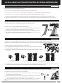
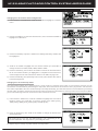
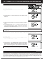
To adjust the Steering Wheel spring tension, follow the step below:
1) To Increase the spring tension of the Steering Wheel (make firmer),
use a 1.5mm hex wrench to turn the Steering Spring Tension
Adjustment Screw (A) clockwise. To Decrease the spring tension
of the Steering Wheel (make softer), turn the Steering Spring
Tension Adjustment Screw counter-clockwise.
The spring tension of the Steering Wheel and Throttle Trigger can be adjusted to best suit the user. Some users may prefer the
Throttle Trigger and/or Steering Wheel to feel 'firmer' and some users may prefer them to feel 'softer'. It all depends on your
personal preference.
A
To adjust the Throttle Trigger spring tension, follow the step below:
1) To Increase the spring tension of the Throttle Trigger (make firmer),
use a 1.5mm hex wrench to turn the Throttle Spring Tension Ad-
justment Screw (A) clockwise. To Decrease the spring tension of
the Throttle Trigger (make softer), turn the Throttle Spring Tension
Adjustment Screw counter-clockwise.
A
Two optional Steering Wheel springs (one soft and one hard) are included should adjusting the spring tension as described
above not give you the desired feel. Use the hard spring for a firmer feel and soft spring for a softer feel.
To install one of the optional Steering Wheel springs, follow the steps below:
1) Use a 7mm nut driver to remove the Steering Wheel retaining nut, then pull the Steering
Wheel straight off.
2) Use a small philips head screwdriver to remove the spring cover retaining screw (A),
then remove the plastic spring cover.
3) Using a small pair of needle nose pliers, carefully unhook the top of the spring from the
metal peg, then remove the spring.
4) Carefully install the desired optional spring, then reinstall the plastic spring cover and
the Steering Wheel. Installation is the reverse of removal.
A
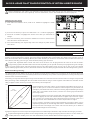
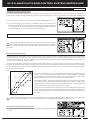
The maximum Right and Left travel of the Steering Wheel can be adjusted to best suit the feel of the Steering Wheel and your
driving style. Some drivers prefer to limit the travel of the Steering Wheel as it makes them feel more 'connected' to their Model.
Limiting the maximum travel of the Steering Wheel will Increase the sensitivity of the Steering. We recommend setting
Negative Exponential or ARC percentage values to Soften the control feel around Neutral. For more information, see the
CURVE Menu
section on pages 78 ~ 82.
To adjust the maximum travel of the Steering Wheel, follow the steps below:
1) Remove the foam Steering Wheel grip from the Steering Wheel by firmly pulling it straight off.
2) To limit the maximum travel of the Steering Wheel, use a 1.5mm hex wrench to turn both grub
screws in the Steering Wheel adapter hub clockwise equally the desired amount. To maximize
the travel of the Steering Wheel, turn both grub screws in the Steering Wheel adapter hub
counter-clockwise equally the desired amount.
After making Steering Wheel travel adjustments, you must use the Variable Rate Adjustment
function to ensure your Steering servo travel limits are equalized. For more information, see
the
VR ADJUST Menu
section on pages 44 ~ 46.

13
TR
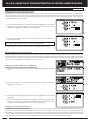
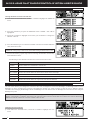
An optional larger diameter Steering Wheel is included to best suit the user. Some user's feel that the larger diameter Steering
Wheel makes the Steering operation seem finer.
To install the optional larger diameter Steering Wheel, follow the steps below:
1) Use a 7mm nut driver to remove the Steering Wheel retaining nut, then pull the Steering Wheel straight off.
2) Remove the foam Steering Wheel grip from the Steering Wheel by firmly pulling it straight off.
3) Pull the Steering Wheel adapter hub from the original Steering Wheel then push it into the optional Steering Wheel.
4) Slide the foam grip over the new Steering Wheel, then reinstall the Steering Wheel. Installation is the reverse of removal.
Two optional Steering Wheel grips (one small and one large) are included to best suit the user. Some user's may find that one of
these two grips feels more comfortable than the normal size stock grip.
To install one of the optional grips, follow the steps below:
1) Remove the original grip from the handle by firmly pulling down on the back of the
grip (at the top), then by pulling the grip out along its Front edges.
2) To install the new grip, align the molded tabs in the grip with the matching slots in the
handle, then firmly push the molded tabs into the slots, working your way around
the grip until the edges of the grip are flush with the handle.
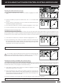
The angle of the Throttle Trigger can be adjusted Right or Left to change the feel of the Throttle Trigger during use. Some users
may prefer the Throttle Trigger straight while some users my prefer the Throttle Trigger angled toward the Right or Left. It all
depends on your personal preference. Two Throttle Trigger adjustment plates are included to fine-tune the angle.
To adjust the Throttle Trigger angle, follow the steps below:
1) Use a philips head screwdriver to remove the Throttle Trigger mounting screw (A) from
the Left side of the transmitter.
2) Use the tip of a modeling knife to carefully pop the trigger adjustment plate (B) out of the
transmitter.
3) Carefully press the desired trigger adjustment plate (B) into the transmitter, making sure to orientate it in the direction you want
to angle the Throttle Trigger, then reinstall and tighten the Throttle Trigger mounting screw (A).
A
B
A - Throttle Trigger Centered
(Stock)
B - Throttle Trigger Angled Slightly.
Angle Right or Left Depending on Orientation.
C - Throttle Trigger Angled More.
Angle Right or Left Depending on Orientation.
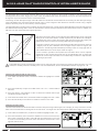
A wrist strap anchor is included that can be installed onto the transmitter to facilitate the use of a wrist strap (not included).
A
B
To install the wrist strap anchor, follow the steps below:
1) Using a 2.5mm hex wrench, remove the wrist strap anchor mounting screw (A)
from the Right side of the transmitter.
2) Slide the wrist strap anchor into the mounting slot in the back of the transmitter,
then reinstall and tighten the wrist strap anchor mounting screw (A).
When installing the wrist strap anchor, note its orientation. The U-Shaped
groove (B) in the base of the wrist strap anchor should be pointing down.

14
TR
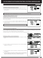
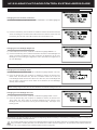
3) When satisfied with the adjustment, tighten the Throttle Trigger mounting
screw (A).
As you adjust the Throttle Trigger position, the Throttle Trigger Position
Adjustment Indicator (C) will move, indicating the current position of
the Throttle Trigger.
The total adjustment range is approximately 5mm. Do not attempt to adjust the Throttle Trigger position beyond the limits
indicated by the Throttle Trigger Position Adjustment Indicator or damage may result. Moving the Throttle Trigger position
does not affect the physical movement of the Throttle Trigger.
The position of the Throttle Trigger can be adjusted forward or backward to change the feel of the Throttle Trigger during use.
Some users may prefer the Throttle Trigger positioned farther forward and some users my prefer the Throttle Trigger positioned
farther back. It all depends on your personal preference.
To adjust the Throttle Trigger position, follow the steps below:
1) Use a philips head screwdriver to loosen the Throttle Trigger mounting
screw (A) from the Left side of the transmitter.
2) To move the Throttle Trigger backward, use a philips head screwdriver
to turn the Throttle Trigger Position Adjustment Screw (B) counter-
clockwise. To move the Throttle Trigger forward, turn the Throttle
Trigger Position Adjustment Screw (B) clockwise.
A
B
C
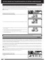
3) Feed the connectors from the Trim Switch assembly
through the hole in the offset plate, then very carefully plug
them into the matching connectors in the transmitter.
4) Being careful not to pinch any connectors or wires, align
and secure the offset plate to the transmitter using one
M3 x 14mm socket-cap screw (B) and two M3 x 8mm
philips head screws (C) included. There are small notches
in both the Trim Switch assembly and the offset plate that
line up with corresponding small tabs in the offset plate
and the transmitter to ensure both the Trim Switch assembly
and the offset plate are installed in the correct orientation.
5) Being careful not to pinch any connectors or wires, align
and secure the Trim Switch assembly to the offset plate
using the three larger philips head screws (D) you removed
previously.
6) Reinstall the Steering Wheel. Installation is the reverse of
removal.
An optional Steering Wheel offset plate is included that lowers the position of the Steering Wheel and the Trim Switch assembly.
Some users may find the Lower Steering Wheel position more comfortable not only for hand position, but also for the overall
balance and feel of the transmitter.
A
A
A
To install the Steering Wheel offset plate, follow the steps below:
1) Use a 7mm nut driver to remove the Steering Wheel retaining nut, then pull the
Steering Wheel straight off and set is aside.
2) Using a philips head screwdriver, remove the three larger philips head screws (A),
then carefully pull the Trim Switch assembly off the transmitter and very carefully
unplug the two connectors.
B
C
D

15
TR
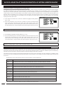
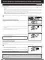
4) Being careful not to pinch any connectors or wires, align and secure the offset
plate to the transmitter using one M3 x 14mm socket-cap screw (B) and
two M3 x 8mm philips head screws (C).
5) Align and secure the angle plate to the offset plate, using the three
M3 x 8mm philips head screws (D) included.
6) Being careful not to pinch any connectors or wires, align
and secure the Trim Switch assembly to the offset
plate using the three larger philips head screws
(E) you removed previously.
7) Reinstall the Steering Wheel. Installation is the
reverse of removal.
Two optional Steering Wheel angle plates (one Right and one Left) are included that angles the position of the Steering Wheel
and Trim Switch assembly. Some users may find that angling the Steering Wheel to the Right or Left may be more comfortable
during use.
A
A
A
To install the Right or Left Steering Wheel angle plate, follow the steps below:
1) Use a 7mm nut driver to remove the Steering Wheel retaining nut, then pull the
Steering Wheel straight off and set is aside.
2) Using a philips head screwdriver, remove the three larger philips head screws (A),
then carefully pull the Trim Switch assembly off the transmitter and very carefully
unplug the two connectors.
C
3) Choose which angle plate you want to install, then align
and secure the angle plate to the transmitter, using the
three M3 x 8mm philips head screws (B) included. There
are small notches in both the Trim Switch assembly and
the angle plate that line up with corresponding small tabs
in the angle plate and the transmitter to ensure both the
Trim Switch assembly and the angle plate are installed in
the correct orientation.
4) Very carefully plug the connectors from the Trim Switch
assembly into the matching connectors in the transmitter.
5) Being careful not to pinch any connectors or wires, align
and secure the Trim Switch assembly to the angle plate
using the three larger philips head screws (C) you removed
previously.
6) Reinstall the Steering Wheel. Installation is the reverse of
removal.
Installation With Offset Plate:
The installation procedures below outline installing either angle plate along WITH
the optional offset plate described in the
Steering Wheel Offset Plate Installation
section on the previous page. Complete steps 1 and 2 above before proceeding.
'R' and 'L' are molded into the angle plates to differentiate them. The 'R' angle plate will angle the Steering Wheel toward the
Right and the 'L' angle plate will angle the Steering Wheel toward the Left.
3) Choose which angle plate you want to install, then feed the connectors from the Trim
Switch assembly through the angle plate and on through hole in the offset plate. Very
carefully plug the connectors into the matching connectors in the transmitter*.
B
B
C
D
E
There are small notches on the back side of
each of the parts that correspond to matching tabs on the Front side of each of the parts and the transmitter to ensure
everything is installed in the correct orientation.
*Do not install the offset plate onto
the transmitter before plugging the
connectors together, otherwise
the connector leads won't be long
enough.
Installation Without Offset Plate:
The installation procedures below outline installing either angle plate WITHOUT the optional offset plate described in the
Steering
Wheel Offset Plate Installation
section on the previous page. Complete steps 1 and 2 above before proceeding.

16
TR
The position of the Steering Wheel can be switched from the Right side to the Left side to accommodate Left-handed drivers. This
makes the M12 much more comfortable for natural Left-handed drivers to use.
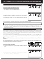
To change the driving position for Left-handed use, follow the steps below:
1) Using a 2.5mm hex wrench, remove the three socket cap screws (A) that hold the display
switch cover in place, then carefully pull the display switch cover off.
A
B
C
A
A
B
2) Using a 2.5mm hex wrench, remove the two socket-cap screws
(B) from the bottom the transmitter that hold the main body in
place.
3) Carefully pull the main body up and off the base (C), being careful not to
damage any of the wiring.
4) Rotate the main body 180º (D), then push it back down onto the
base (E), being careful not to pinch any of the wiring.
5) Reinstall the two socket-cap screws you removed previously to secure
the main body to the base.
6) Reinstall the display switch cover. Installation is the reverse of removal.
When reinstalling the display switch cover, make sure to install the
two machine screws into the sides of the cover and the one
self-tapping screw in the top of the cover.
D
E
Changing the Direction of the Push-Button Rotary Dial:
When you switch the driving position as described above, the direction the Push-Button Rotary Dial moves the Programming
Cursor will be reversed. If desired, the direction the Push-Button Rotary Dial moves the Programming Cursor can be changed.
To change the direction the Push-Button Rotary Dial moves the Programming Cursor, follow the step below:
1) Press and HOLD the ENTER key, then turn the transmitter ON. Release the ENTER key AFTER the transmitter finishes initializing
and beeps once.
Activating the Left Side Switches:
Two duplicate switches (Sw3 and Trm5) are positioned on the left side of the transmitter for use in the left-handed driving
position. In the default configuration, these switches are Inhibited for right-handed use. When you switch the driving position as
described above, you will want to Activate these switches for ease of use.
To Activate the Sw3 and Trm5 switches on the Left side of the transmitter, follow the steps below:
1) Remove the battery cover from the bottom of the transmitter, then remove the battery holder.
2) Flip the switch that's in the base of the transmitter below the battery holder toward the Front of the transmitter. When the
switch is toward the Front of the transmitter, the left-hand switches will be Active and when the switch is toward the back of
the transmitter, the right-hand switches will be Active.

17
TR
Scrolls between STATUS, ASSIGN and TELEMETRY screens.
Scrolls the Programming Cursor RIGHT or UP and LEFT or
DOWN. Increases or Decreases Programming Values.
PROGRAMMING KEY NAME FUNCTION
Push-Button Rotary Dial
(Push ENTER)
Opens the Selected menu or programming option. Press and
HOLD to reset the Selected programming option to its default
value.
BACK Key
Returns to the previous menu. Repeatedly press to return to the
STATUS screen.
Push-Button
Rotary Dial
(Scroll UP/DOWN)
Moving around the various screens and programming the transmitter is accomplished using the ENTER key (Push-Button Rotary
Dial), the SELECT switch and the BACK key.
PRO TIP: While navigating Programming Menus and changing Programming Values, keep the following in mind: to choose
a menu from the STATUS screen, use the SELECT switch. To open a menu, press the ENTER key. To choose an option
to program, scroll UP or DOWN to highlight the desired option, then press the ENTER key. The highlighted option will flash,
indicating the Programming Value can be changed. Once you've changed the Programming Value, press the ENTER key again
or press the BACK key and the highlighted option will stop flashing, indicating you can scroll UP or DOWN to highlight another
programming option. To reset a programming option to its default value, highlight the option and press the HOLD the ENTER key.
Used to Select various menus. In addition, the SELECT switch's
function will vary depending on the menu chosen and will be
indicated in the menu's Message Display Window.
In the default configuration, when you turn the M12 transmitter ON, the transmitter will start-up and display the BOOT screen
temporarily, then display the STATUS screen.
SELECT Switch
BOOT Screen: The BOOT screen is displayed when the transmitter is turned ON. The BOOT screen can be disabled. For more
information, see the
BOOT Menu
section on page 56.
STATUS Screen: The STATUS screen is displayed after the BOOT screen and displays important information about the
transmitter. It's also a base from which you access other Programming Menus. For more detailed information, see the
STATUS
Screen Overview
section on the next page.
STATUS Screen
BOOT Screen

18
TR
Use the information in this section to familiarize yourself with the layout and different indicators and displays that comprise the
STATUS screen. The STATUS screen displays all pertinent information, such as the Model Name, Modulation Type, Timer, Voltage
and much more.
The STATUS screen will always be displayed after the BOOT screen unless you change that option in the SYSTEM BOOT menu.
For more information, see the
BOOT Menu
section on page 56.
Model Number Model Name
Voltage Indicator
Telemetry Signal Indicator
Modulation Type Indicator
On-Time Indicator
Audio Indicator
RF Indicator
Trim Display
Dual Rate Display
Mode Display
Car Type Indicator
Racing Mode Indicator
Trim Display
ASSIGN Screen: The ASSIGN screen displays the functions that are currently Assigned to the Push-Button Switches, the Trim
Switches, the Auxiliary Dial and the Auxiliary Lever, all in one convenient location.
TELEMETRY Screen: The TELEMETRY screen displays Telemetry Data, such as RPM or Speed, Temperature, Receiver Voltage
and more. Use the SELECT switch to switch between ALL and LAP, ST, TH, RPM, VOLT, TMP1 and TMP2 pages.
Telemetry integration requires the use of an Airtronics 2.4GHz FH4T Telemetry-capable surface receiver, such as the RX-461
or RX-462. Steering and Throttle Output and Lap Times can still be viewed when used other types of receivers.
TELEMETRY Screen
ASSIGN Screen
From the STATUS screen, use the Push-Button Rotary Dial to scroll UP or DOWN to display the ASSIGN and TELEMETRY
screens. To return to the STATUS screen, either scroll to it or press the BACK key.
SCROLL
STATUS Screen Overview Diagram Descriptions:
Audio Indicator: Indicates whether Audible Key Tones and Transmitter Alarms are Muted or not.
Car Type Indicator: Indicates the current Car Type Selected.
Dual Rate Display: Displays the current Dual Rate percentage value of channels that Dual Rate can be programmed for. Channels
displayed will vary based on the currently Selected Car Type.
Mode Display: Displays any special Programming Modes that are Active, such as Throttle Offset or Anti-Lock Braking.
Model Name: Displays the Name of the currently Selected Model.
Model Number: Displays the number of the currently Selected Model.
Modulation Type Indicator: Indicates the current Modulation Type that the transmitter is set to.
STATUS Screen Overview Diagram:

19
TR
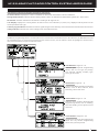
The M12 features four main menus that are accessed from the STATUS screen. Each of the four main menus include a number
of different Programming Menus. The four main menus consist of the SYSTEM menu, the SETUP menu, the RACING menu and
the CUSTOM menu. To access these menus from the STATUS screen, use the SELECT switch to highlight the desired menu,
then press ENTER key to open the Selected menu.
ENTER
SYSTEM Menu: Pages 24 ~ 61.
Features system-specific Pro
gramming
Menus, such as Car Type, Key Assign,
LCD Contrast, Binding, Auxiliary Type,
Trim Type and more.
STATUS Screen Overview Diagram Descriptions, Continued....
On-Time Indicator: Displays the current cumulative On-Time of the transmitter in Hours and Minutes.
Racing Mode Indicator: Indicates whether Racing Mode is Active or Inhibited and Which Racing Mode (R1 ~ R5) is Active.
RF Indicator: Indicates whether the transmitter is sending an RF signal or not.
Trim Display: Displays the current position of channel Trim. Trim Indicators (ST, AUX1, etc.) displayed will vary based on the
currently Selected Car Type.
Telemetry Signal Indicator: Indicates the current signal strength of the Telemetry connection between the transmitter and receiver.
Voltage Indicator: Indicates the current Voltage of the transmitter batteries.
SETUP Menu: Pages 61 ~ 74.
Features basic Model-specific Program
ming
Menus, such as EPA, Sub-Tim, Servo
Re
versing, Timers and more.
RACING Menu: Pages 74 ~ 93.
Features more complex Model-specific
Programming Menus, such as C-Mixing,
Anti-Lock Braking, Servo Speed, Curves
and more.
CUSTOM Menu: Pages 94 ~ 95.
Features the Channel Set Programming
Menu and any favorite Programming
Menus that you add yourself.
ENTER
ENTER
ENTER
SELECT
SELECT
SELECT

20
TR
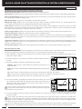
The four main menus described in the previous section all share the same basic layout as illustrated below. Use this information
to familiarize yourself with the layout and the information presented.
Model Number
System Indicators
Menu Programming Display
Current Programming Menu
Message Display
Racing Mode Indicator
Next Programming Menus
Next Programming Menus
Current Main Menu
Menu Header
Current Main Menu: Displays the currently Active main menu, either SYSTEM, SETUP, RACING or CUSTOM.
Current Programming Menu: Displays the currently Active Programming Menu.
Menu Header: Displays the name of the currently Active Programming Menu. In some cases, programming options may also be
found within the Menu Header.
Menu Programming Display: Displays all programming information pertinent to the currently Active Programming Menu.
Message Display: Displays different Programming Key functions based on the currently Active Programming Menu. For more
information, see the illustrations and descriptions below.
Model Number: Displays the number of the currently Selected Model.
Next Programming Menus: Displays the next two Programming Menus within the current main menu.
Racing Mode Indicator: Indicates which Racing Mode (R1 ~ R5) is Active or Inhibited.
System Indicators: Indicates current transmitter status information as described in the
Display Screens Overview
section on
pages 17 ~ 19.
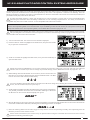
The function of the SELECT switch and the ENTER key will vary depending on the specific Programming Menu displayed.
In This Menu Style:
The SELECT switch Saves or Removes the current Programming Menu from the
CUSTOM menu.
The ENTER key opens the highlighted Programming Menu. Scroll UP and DOWN
to choose different Programming Menus.
In This Menu Style:
The ENTER key opens a Sub-Menu. Scroll UP and DOWN to choose different
Sub-Menus.
In This Menu Style:
The SELECT switch scrolls RIGHT or LEFT to Select different channels.
Scroll UP and DOWN to choose the desired function Programming Value, then
press the ENTER key change the Programming Value.
Page is loading ...
Page is loading ...
Page is loading ...
Page is loading ...
Page is loading ...
Page is loading ...
Page is loading ...
Page is loading ...
Page is loading ...
Page is loading ...
Page is loading ...
Page is loading ...
Page is loading ...
Page is loading ...
Page is loading ...
Page is loading ...
Page is loading ...
Page is loading ...
Page is loading ...
Page is loading ...
Page is loading ...
Page is loading ...
Page is loading ...
Page is loading ...
Page is loading ...
Page is loading ...
Page is loading ...
Page is loading ...
Page is loading ...
Page is loading ...
Page is loading ...
Page is loading ...
Page is loading ...
Page is loading ...
Page is loading ...
Page is loading ...
Page is loading ...
Page is loading ...
Page is loading ...
Page is loading ...
Page is loading ...
Page is loading ...
Page is loading ...
Page is loading ...
Page is loading ...
Page is loading ...
Page is loading ...
Page is loading ...
Page is loading ...
Page is loading ...
Page is loading ...
Page is loading ...
Page is loading ...
Page is loading ...
Page is loading ...
Page is loading ...
Page is loading ...
Page is loading ...
Page is loading ...
Page is loading ...
Page is loading ...
Page is loading ...
Page is loading ...
Page is loading ...
Page is loading ...
Page is loading ...
Page is loading ...
Page is loading ...
Page is loading ...
Page is loading ...
Page is loading ...
Page is loading ...
Page is loading ...
Page is loading ...
Page is loading ...
Page is loading ...
Page is loading ...
Page is loading ...
Page is loading ...
Page is loading ...
Page is loading ...
Page is loading ...
Page is loading ...
Page is loading ...
Page is loading ...
Page is loading ...
Page is loading ...
Page is loading ...
Page is loading ...
Page is loading ...
Page is loading ...
Page is loading ...
Page is loading ...
Page is loading ...
Page is loading ...
Page is loading ...
-
 1
1
-
 2
2
-
 3
3
-
 4
4
-
 5
5
-
 6
6
-
 7
7
-
 8
8
-
 9
9
-
 10
10
-
 11
11
-
 12
12
-
 13
13
-
 14
14
-
 15
15
-
 16
16
-
 17
17
-
 18
18
-
 19
19
-
 20
20
-
 21
21
-
 22
22
-
 23
23
-
 24
24
-
 25
25
-
 26
26
-
 27
27
-
 28
28
-
 29
29
-
 30
30
-
 31
31
-
 32
32
-
 33
33
-
 34
34
-
 35
35
-
 36
36
-
 37
37
-
 38
38
-
 39
39
-
 40
40
-
 41
41
-
 42
42
-
 43
43
-
 44
44
-
 45
45
-
 46
46
-
 47
47
-
 48
48
-
 49
49
-
 50
50
-
 51
51
-
 52
52
-
 53
53
-
 54
54
-
 55
55
-
 56
56
-
 57
57
-
 58
58
-
 59
59
-
 60
60
-
 61
61
-
 62
62
-
 63
63
-
 64
64
-
 65
65
-
 66
66
-
 67
67
-
 68
68
-
 69
69
-
 70
70
-
 71
71
-
 72
72
-
 73
73
-
 74
74
-
 75
75
-
 76
76
-
 77
77
-
 78
78
-
 79
79
-
 80
80
-
 81
81
-
 82
82
-
 83
83
-
 84
84
-
 85
85
-
 86
86
-
 87
87
-
 88
88
-
 89
89
-
 90
90
-
 91
91
-
 92
92
-
 93
93
-
 94
94
-
 95
95
-
 96
96
-
 97
97
-
 98
98
-
 99
99
-
 100
100
-
 101
101
-
 102
102
-
 103
103
-
 104
104
-
 105
105
-
 106
106
-
 107
107
-
 108
108
-
 109
109
-
 110
110
-
 111
111
-
 112
112
-
 113
113
-
 114
114
-
 115
115
-
 116
116


AIRTRONICS M12 User manual
- Category
- Remote controlled toys
- Type
- User manual
Ask a question and I''ll find the answer in the document
Finding information in a document is now easier with AI
Related papers
-
AIRTRONICS MT-4s User manual
-
-
-
-
-
-
-
-
-
Other documents
-
Futaba AZPT3PN-75 User manual
-
 Sanwa Electronic Instrument L73-90490 User manual
-
Spektrum TM1100 DSMX Fly-By Aircraft Telemetry Module Operating instructions
-
 TURBO RACING 91805G-VT User manual
-
-
Absima CR4T User manual
-
Sanwa MT-44 User manual
-
 QuickTrick Roll on Turnplates Set User guide
-
-
 Sanwa Electronic Instrument L73-92082 User manual


