Page is loading ...

1
T R

2
T R
The packaging of your radio control system has been specially designed for the safe transportation and storage of the radio
control system's components. After unpacking your radio control system, do not discard the packaging materials. Save the
packaging materials for future use if you ever need to send your radio control system to us for service or to store your radio
control system if you don't plan on using it for an extended period of time.
We appreciate your purchase of the new Airtronics MT-4S 2.4GHz FHSS-4T radio control system. This User's Guide is intended
to acquaint you with the many unique features of your state of the art Telemetry-capable radio control system. Please read this
User's Guide carefully prior to use so that you may obtain maximum success and enjoyment from the operation of your new
radio control system.
The MT-4S 2.4GHz FHSS-4T radio control system has been designed for the utmost in comfort and precise control of all types
of model cars and boats. We wish you the best of success and fun with your new purchase!
Additional 2.4GHz FH2, FH3, FH4 and FH4T surface receivers* can be purchased and paired with the MT-4S. Due to
differences in the implementation of 2.4GHz technology among different manufacturers, only Airtronics brand 2.4GHz
surface receivers are compatible with your radio control system. Telemetry functions are available only when used with
Telemetry-capable receivers (available separately). Visit your local Airtronics dealer or our website at http://www.airtronics.net
for more information.
*Not all Features are Supported by all Types of Receivers. Some Features Limited by Receiver Type
Introduction.....................................................................................................................................................................................................................................Page 3
Safety ..........................................................................................................................................................................................................................................Page 3
FCC Compliance Statement ...........................................................................................................................................................................................Page 3
Usage Precautions......................................................................................................................................................................................................................Page 4
2.4GHz Frequency Band Precautions ........................................................................................................................................................................Page 4
Transmitter Precautions....................................................................................................................................................................................................Page 4
Receiver Precautions .........................................................................................................................................................................................................Page 4
Features and Specifications ..................................................................................................................................................................................................Page 5
System Features ...................................................................................................................................................................................................................Page 5
System Specifications .......................................................................................................................................................................................................Page 5
Servo Recommendations ................................................................................................................................................................................................Page 5
Features Familiarization ...........................................................................................................................................................................................................Page 6
Transmitter Features Diagrams ....................................................................................................................................................................................Page 6
Receiver Features Diagram ............................................................................................................................................................................................Page 8
Transmitter and Receiver Features Descriptions .................................................................................................................................................Page 8
Servo Connectors ................................................................................................................................................................................................................Page 9
Transmitter Safety Alarms and LED Condition Indicators ...............................................................................................................................Page 9
System Connections ............................................................................................................................................................................................................... Page 11
Transmitter Battery Options ......................................................................................................................................................................................... Page 11
Alkaline Battery Installation .......................................................................................................................................................................................... Page 11
Transmitter Battery Charging Options .................................................................................................................................................................... Page 11
Warnings if Using Li-Po or Li-Fe/A123 Transmitter Batteries ...................................................................................................................... Page 11
Receiver Connections and Mounting ..................................................................................................................................................................... Page 12
Telemetry Connections and Mounting................................................................................................................................................................... Page 13
Adjustments and Options ..................................................................................................................................................................................................... Page 14
Throttle Trigger Position Adjustment ....................................................................................................................................................................... Page 14
Throttle Trigger Angle Adjustment ............................................................................................................................................................................ Page 14
Grip ........................................................................................................................................................................................................................................... Page 14
Throttle Trigger and Steering Wheel Spring Tension Adjustment ........................................................................................................... Page 15
Steering Wheel Travel Adjustment ........................................................................................................................................................................... Page 15
Wrist Strap Anchor ............................................................................................................................................................................................................ Page 15
LCD and Programming Keys .............................................................................................................................................................................................. Page 16
Top Screen and Telemetry Screen Overview ..................................................................................................................................................... Page 16
Programming Keys Overview and Functions ..................................................................................................................................................... Page 17
Transmitter and Receiver Binding.................................................................................................................................................................................... Page 18
Programming Menus.............................................................................................................................................................................................................. Page 19
Overview (Includes Complete Programming Menu List) ............................................................................................................................. Page 19
System Menus ........................................................................................................................................................................................................................... Page 51
Overview (Includes Complete System Menu List) ........................................................................................................................................... Page 51
Reference...................................................................................................................................................................................................................................... Page 73
Troubleshooting Guide ................................................................................................................................................................................................... Page 73
Glossary of Terms ............................................................................................................................................................................................................. Page 74
Index ........................................................................................................................................................................................................................................ Page 79
Notes ....................................................................................................................................................................................................................................... Page 87


4
T R
• The 2.4GHz frequency band may be used by other devices, or other devices in the immediate area may cause interference
on the same frequency band. Always before use, conduct a bench test to ensure that the servos operate properly. Also,
conduct checks with the transmitter as distant as possible from your Model.
• The response speed of the receiver can be affected if used where multiple 2.4GHz transmitters are being used, therefore,
carefully check the area before use. If response seems slow during use, stop your Model immediately and discontinue use.
• If the 2.4GHz frequency band is saturated (too many transmitters turned ON at once), as a safety precaution, the transmitter
and receiver may not Bind. This ensures that your radio control system does not get hit by interference. Once the frequencies
have been cleared, or the saturation level has dropped, your transmitter and receiver should Bind without any problems.
• To prevent possible damage to your servos or a runaway model, turn the transmitter ON first,
then turn the receiver ON. After running your model, turn the receiver OFF first, then turn the
transmitter OFF.
• Before use, double-check that the transmitter and receiver batteries have sufficient
power.
• The transmitter antenna is mounted internally and is located in the vertical back portion of the carrying handle.
Do NOT cover the carrying handle in any way during use! Doing so can block the RF signal, resulting in loss of
control of your model.
• During use, hold the transmitter so that its orientated as close to vertical as possible at all times. This provides the best RF
signal between the transmitter and the receiver. Try not to ever 'follow' your model with the transmitter,
as this can result in a weakened RF signal.
• Do not expose the transmitter or any other components to excessive heat,
moisture, fuel, exhaust residue, etc.
• If the outer case becomes dirty, it can be cleaned with a soft dry cloth. If the outer case becomes
soiled, it can be cleaned with a damp cloth and liquid detergent. Do not use any solvents to clean
• The antenna consists of a coaxial cable and a reception wire (the thin tip at the end of the coaxial cable). When you mount
the antenna, do not bend the reception wire. Reception performance decreases if the reception wire is bent.
• The antenna is delicate, therefore, handle with care. Do not pull on the antenna with force. Do
not cut or extend the antenna.
• The coaxial cable (the thicker portion of the antenna) can be bent into gentle curves, however,
do not bend the coaxial cable acutely, or repeatedly bend it, or the antenna core can be damaged.
• The antenna should be installed into a vertical plastic tube per your particular model's assembly instructions. Keep the
receiver antenna as far away from the motor, battery and ESC as possible.
• There is a danger of runaway operation if connectors shake loose during use. Make sure that the receiver, servo(s) and
switch connectors are securely fitted.
• The receiver is susceptible to vibration, shock and moisture. Take appropriate measures to protect against vibration and
moisture. Failure to take appropriate measures could result in runaway operation or damage to the receiver. We suggest
wrapping the receiver in shock-absorbing foam or securing it with double-sided foam tape when installing it into your
model.
• When routing the antenna, avoid contact with any carbon or metal chassis components. Contact between metal or carbon
parts can result in electrical noise, which can adversely effect receiver performance and possibly result in runaway operation
and result in damage to your model.
• With electric-powered models, be sure to fit any brushed motors with a noise suppression capacitor. Without a noise suppression
capacitor, excessive electrical noise generation can cause runaway operation and result in damage to your model.
the outer case. Solvents will damage the finish.
• Full telemetry support requires the use of an Airtronics 2.4GHz FH4T telemetry-capable surface receiver, such as the RX-461
or RX-462 (available separately). The included RX-472 receiver can send telemetry data for the voltage of the receiver battery
pack only, unless used with the Airtronics Super Vortex ZERO ESC (available separately). See below.
• Full Telemetry support is provided when used with an Airtronics Super Vortex ZERO ESC plugged into the BATT/SSL slot of
the included RX-472 receiver.
• The range of the Telemetry System is approximately 260 feet (80 meters), although the range can vary based on many
environmental factors. Use the Telemetry Signal Indicator to determine the quality of the signal.

5
T R
• Adjustable Steering Wheel
• Adjustable Grip
• Variable Rate Adjustment
• Model Naming
• Model Select
• Direct Model Select
• Model Clear
• Selectable Modulation Type
• Multi-Function LCD Contrast
• Adjustable Key Volume and Tone
• Programmable Low Voltage Alarm
• Inactivity and Over Voltage Alarms
• Digital Battery Voltage Monitor
• 18 Model Memory
• Telemetry Logging
• Channel Set Menu
• Servo Reversing
• Steering, Throttle and Brake Dual Rate
• End Point Adjustment
• Exponential and ARC Adjustment
• Servo Speed Adjustment
• Anti-Lock Braking
• Throttle Offset
• Lap and Interval Timers
• Total, Best and Individual Lap Display
• Four Wheel Steering Mixing
• Dual Throttle Mixing w/Dig & Burn
• Normal, SSR and SHR Servo Modes
• Center or Parallel Trim Types
• Code Auxiliary
• Step Auxiliary
• Point Auxiliary
• Auxiliary Mixing
• Programmable Fail Safe
• Receiver Battery Voltage Fail Safe
• Digital Trims
• Servo Sub-Trim
• Adjustable Throttle Trigger
• Programmable Switches, Lever and Dial
Transmitter:
• Model: MT-4S
• Output Power: 100mW
• Nominal Input Voltage: 4.8v to 7.4v
• Operating Voltage Range: 4.0v to 9.6v
• Dry Weight: 13.68oz (388g)
• Frequency: 2.4GHz FHSS
• Modulation Type: FH2, FH3, FH3F, FH4T, FH4FT
Receiver:
• Model: RX-472 Super Response w/SSL Support
• Nominal Input Voltage: 3.7v to 7.4v
• Weight: 0.23oz (6.6gr)
• Dimensions: 1.18 x 0.91 x 0.55in (30.0 x 23.3 x 14.0mm)
• Frequency: 2.4GHz FH3/FH4T Selectable Via Transmitter
• Fail Safe Support: Yes (All Channels)
• Battery Voltage Fail Safe Limit: 3.5 to 5.0v (FH3) / 3.5 to 7.4v (FH4T)
• MT-4S FH4T Digital High-Response Telemetry Transmitter
• RX-472 Super Response Receiver w/SSL Support
• On/Off Switch
• Dry Cell Receiver Battery Holder
• Wrist Strap Mount
• Optional Large Grip
• Optional Throttle Trigger Angle Brackets
• Receiver Dust Boot Covers
The following items should be included with your radio control system. If an item is missing or appears damaged, please
contact your local Airtronics distributor. For more information, see the Service and Support section on page XX.
• 4-Channel 2.4GHz FH4T Digital High-Response Telemetry System with Advanced Programming
• Backlit LCD Screen Allows You to Easily View Programming Options and Telemetry Data in All Types of Conditions
• High-Power FH4T Technology Provides the Best Reception and Connectivity, Giving Racers Added Assurance
• 4-Cell Dry Battery Holder for Lighter Weight - Also Accepts Optional Ni-Cd/Ni-MH Batteries or 2S Li-Po/Li-Fe Battery Packs
• Includes RX-472 2.4GHz FH4T Super Response Receiver w/Sanwa Synchronized Link Support
Transmitter Battery:
• 4 'AA' Alkaline or Ni-Cd/Ni-MH cells or 2S LiPo or 2S LiFe battery pack.
Receiver Battery:
• 4 'AA' Alkaline or Ni-Cd/Ni-MH cells or 4 to 6 cell Ni-Cd/Ni-MH battery pack or 2S LiPo battery pack.
Servos and ESCs:
• We recommend using digital servos and ESCs that support a high frame rate whenever possible. Due to the extremely
high frame rate of the MT-4S transmitter, analog servos and many ESCs may not be compatible when used in SHR or
SSR servo mode. To prevent compatibility issues, use analog servos only in NOR servo mode. If your ESC does not work
in SHR servo mode, use NOR servo mode. Any brand and type of digital servo can be used in NOR or SHR servo mode.
Airtronics/Sanwa SRG series digital servos are only compatible with SSR servo mode (highest frame rate).
GENERAL

6
T R
Use the diagrams in this section to familiarize yourself with the layout of your transmitter. Descriptions of these features can be
found in the Transmitter and Receiver Overview Diagram Descriptions section on pages XX and XX.
The transmitter antenna is mounted internally and is located in the vertical back portion of the carrying handle. Do NOT
cover the carrying handle in any way during use! Doing so can block the RF signal, resulting in loss of control of your
model. During use, hold the transmitter so that its orientated as close to vertical as possible at all times. This provides the best
RF signal between the transmitter and the receiver. Try not to ever 'follow' your model with the transmitter, as this can result in
a weakened RF signal.
Antenna
(Inside Handle)
Trim Switch
(Trm1)
Battery Compartment
Dial Knob
Throttle Trigger
Grip
Push-Button
Switch (Sw1)
Trim Switch
(Trm2)
Trim Switch (Trm3)
Trim Switch
(Trm4)
Auxiliary Lever
Throttle Trigger Tension
Adjustment Screw
Push-Button
Switch (Sw2)
Throttle Trigger Position
Adjustment Screw
Steering Wheel Tension
Adjustment Screw
Wrist Strap
Anchor Slot
Power Switch

7
T R
Multi-Function LCD LED 1/2
Push-Button
Rotary Dial
(Up/Down/Enter Key)
Back/Cancel Key
Dial Knob
Trim Switch (Trm1)Trim Switch (Trm2)
Trim Switch (Trm3)Trim Switch (Trm4)
Wrist Strap
Anchor Slot
Charging Jack
Throttle Trigger Position
Adjustment Indicator
Power Switch
Grip
Antenna
(Inside Handle)
GENERAL

8
T R
Antenna: Transmits the signal from the transmitter to the receiver in the model. Never touch the Antenna during use. Doing so
may result in a weakened RF signal or complete loss of control of your model.
Antenna Reception Wire: The portion of the receiver antenna that receives the transmitter signal. The Antenna Reception Wire
should never be bent or it could be damaged and limit the range of your model.
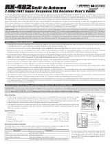
Use the diagrams in this section to make receiver connections and to familiarize yourself with the RX-472 4-Channel 2.4GHz
FH4T Super Response receiver included with your MT-4S radio control system. Descriptions of the features can be found in the
Transmitter and Receiver Features Descriptions
section below and on the next page.
If using the Sanwa Super Vortex ZERO or other SSL compatible ESC, plug the ESC into the BATT/SSL slot, otherwise
SSL features and telemetry data will not be available. All other ESC's should be plugged into the CH 2 TH port.
The receiver's Nominal Input Voltage is 3.7 to 7.4 volts. A 2 cell LiPo or LiFe battery pack can be used to power the receiver
without the use of a voltage regulator. In addition, this allows you to take advantage of the Higher torque and speed
provided by using 7.4 volt digital servos.
Use a 2 cell LiPo or LiFe battery pack ONLY if your servos are rated to handle the Higher voltage.
• We suggest binding the transmitter and receiver and making all receiver connections to check for correct
operation prior to mounting the receiver in your model.
• The receiver should be mounted as far away from any electrical components as possible. When routing
the antenna, avoid contact with any carbon or metal chassis components. Contact between metal or
carbon parts can result in electrical noise, which can adversely effect receiver performance and possibly
result in runaway operation and result in damage to your model.
• Route the receiver antenna up through a plastic tube so that it is in the vertical position. Do not bend the reception wire.
Reception performance decreases if the reception wire is bent. Do not pull on the antenna with force. Do not cut or extend
the antenna. The coaxial cable can be bent into gentle curves, however, do not bend the coaxial cable acutely, or repeatedly
bend it, or the antenna core can be damaged.
• To protect the receiver from vibration and other damage, we recommend wrapping the receiver in shock absorbing foam
or using double-sided foam tape when installing it in your model.
As a safety precaution, set your model on a stand so the wheels are off the ground before turning on your radio control
system or connecting your motor for the first time.
Bind Button
= Signal
= Positive
= Negative
Bind LED
Coaxial Cable
Antenna
Reception Wire
Steering
Channel 1
Throttle
Channel 2
Auxiliary 1
Channel 3
Auxiliary 2
Channel 4
On/Off Switch 'AA' Dry Cell Battery Holder,
4.8v to 7.4v Ni-Cd/Ni-MH Battery Pack or
2S LiPo/LiFe Battery Pack
On/Off Switch
To Battery
To Motor
ESC
Throttle
Channel 2
Glow/Gas
Setup
ESC
Setup
Antenna Tube
Coaxial Cable
Antenna
Reception Wire
Bind LED Condition Indicator:
The Bind LED on the receiver can be used to determine receiver condition at a glance. The Bind LED will alert you to various
receiver conditions, as shown in the table below.
Blue
Blue
Red & Blue
Red
Receiving RF Signal
Binding Operation
Receiver Battery Fail Safe Activates
No RF Signal After Receiver Battery Fail Safe Activates
LED COLOR RECEIVER STATUS
LED CONDITION
ON
Slow Flash/Fast Flash
Flash
ON
Optional Airtronics Super Vortex
ZERO ESC w/SSL

9
T R
The receiver uses Airtronics 'Z' connectors, which are electronically compatible with the servos of other radio control system
manufacturers. The connectors are rugged, but should be handled with care.
When unplugging the servo connector, don't pull on the servo wire itself. This could result in damage to the servo wire
pins in the plastic plug. Always grasp the plastic connector itself.
– = Negative (Black)
+ = Positive (Red)
S = Signal (Blue)
If using another brand of servo, double-check the polarity
of the servo connector prior to plugging it into the receiver.
GENERAL
Auxiliary Lever: The Auxiliary Lever is programmable and will perform a different function depending on what function is
assigned to it. For example, it can be used to control Auxiliary 1 Channel 3 or to control the Servo Speed function.
Back/Cancel Key: Pressing the Back/Cancel Key returns the Programming Cursor to the previous menu. Press and HOLD the
Back/Cancel Key to return to the TOP screen. Display functions are shown on the Multi-Function LCD.
Battery Compartment: Houses the four 'AA' Alkaline cells that power the transmitter. Alternatively, the transmitter can be
powered using four 'AA' Ni-Cd or Ni-MH rechargeable batteries or a 2S LiPo or 2S LiFe battery pack.
Bind Button: Used in the process of binding the transmitter and receiver.
Bind LED: Displays the current status of the receiver.
Charging Jack: Used for onboard charging of optional Ni-Cd or Ni-MH batteries. Only the recommended Airtronics 110v AC
charger (95034) should be used through the Charging Jack. If using an after-market Peak-Detection charger or other type of fast
charger, the batteries should be removed from the transmitter to avoid damage to the transmitter circuitry and/or your batteries.
Do not attempt to charge a LiPo or LiFe battery pack through the Charging Jack.
Coaxial Cable: The portion of the receiver antenna that extends the Antenna Reception Wire. The Coaxial Cable can be bent
into gentle curves, however, do not bend it acutely, or repeatedly bend it, or the antenna core can be damaged.
Dial Knob: The Dial Knob can rotate 360º and is programmable to perform a different function depending on what function is
assigned to it. For example, it can be used to increase and decrease Programming Values, control a Trim function or control
an Auxiliary Channel.
Grip: The Grip is molded from rubber in an ergonomic shape for increased comfort, control and feel. An optional Grip is
included that some users may find feels more comfortable.
LED 1/2: Displays the current signal output status of the transmitter (LED 1 - Blue) and the Telemetry connection (LED 2 - Red).
In addition, one or both LEDs are used to indicate various transmitter conditions.
Multi-Function LCD: The heart of the programming and display features of the transmitter. All programming and transmitter
display functions are shown on the Multi-Function LCD.
Power Switch: Turns the transmitter ON and OFF.
Push-Button Rotary Dial: The Push-Button Rotary Dial (also referred to as the Up Key, Down Key, or Enter key) is used along
with the Back/Cancel Key to facilitate transmitter programming. It allows you to quickly and easily navigate the various
Programming Menus and switch between the TOP screen and the Telemetry Screen.
Push-Button Switch: The transmitter features two separate Push-Button Switches in different locations (Sw1 and Sw2). Each
Push-Button Switch is programmable and will perform a different function depending on what function is assigned to it.
Steering Wheel: Proportionally operates the model's right and left steering control. The Steering Wheel features a foam grip for
increased comfort, control and feel. In addition, the Steering Wheel spring tension and travel limits can be adjusted.
Steering Wheel Tension Adjustment Screw: Used to adjust the spring tension of the steering wheel to best suit the feel of
the user.
Throttle Trigger: Controls the speed of the model, both forward and backward, or the model's brake. The Throttle Trigger position,
angle and spring tension can all be adjusted.
Throttle Trigger Position Adjustment Indicator: Indicates the current position of the Throttle Trigger. As the throttle trigger
position is adjusted forward or backward, the Throttle Trigger Position Adjustment Indicator will move forward or backward.
Throttle Trigger Tension Adjustment Screw: Used to adjust the spring tension of the throttle trigger to best suit the feel of
the user.
Throttle Trigger Position Adjustment Screw: Used to adjust the position of the Throttle Trigger either forward or backward.
Trim Switch: The transmitter features four separate Trim Switches positioned around the steering wheel (Trm1, Trm2, Trm3
and Trm4). Each Trim Switch is programmable and will perform a different function depending on what function is assigned
to it. For example, Trm1 and Trm2 can be used to adjust steering and throttle Trim and Trm4 and Trm5 can be used to adjust
Dual Rate and steering EPA.
Wrist Strap Anchor Slot: Used to attach the wrist strap anchor to the transmitter.

10
T R
Low Voltage Alert Alarm:
The Low Voltage Alert alarm will sound when the transmitter batteries reach the Alert Voltage
value programmed in the SYSTEM - ALARM menu. The alarm will sound each time the transmitter
battery voltage decreases by 0.1 volt. To clear this alarm, press the Back/Cancel key or the Push-
Button Rotary Dial. For more information, see the Voltage Alarm section on pages XX and XX.
Temperature Alert Alarm:
The Temperature Alert alarm will sound when the TEMP1 and/or TEMP2 temperature reaches the
Alert Temperature value programmed in the SYSTEM - TELEMETRY menu. To clear this alarm,
press the Back/Cancel key or the Push-Button Rotary Dial. For more information, see the Changing
the Alert Temperature Value section on page XX.
Voltage Alert Alarm:
The Voltage Alert alarm will sound when the receiver battery in your model reaches the Alert
Voltage value you've programmed in the SYSTEM - TELEMETRY menu. To clear this alarm, press
the Back/Cancel key or the Push-Button Rotary Dial. For more information, see the Changing the
Alert Voltage Value section on pages XX and XX.
Inactivity (Power ON) Alarm:
The Inactivity Alarm will sound if the transmitter is left on for a period of 10 minutes without any
control input from the user. This alarm alerts you to prevent unwanted draining of the transmitter
battery. To clear this alarm, either turn the transmitter OFF or press the Back/Cancel key or the
Push-Button Rotary Dial.
Low Voltage Limit Alarm:
The Low Voltage Limit alarm will sound when the transmitter batteries reach the Limit Voltage
value programmed in the SYSTEM - ALARM menu. This alarm can only be cleared by turning the
transmitter OFF and recharging or replacing the transmitter batteries. For more information, see
the Voltage Alarm section on pages XX and XX.
LED 1 (Blue) and LED 2 (Red) can be used to determine various transmitter conditions at a glance. The LEDs will alert you to
various warnings and other transmitter conditions, as shown in the table below.
The MT-4S transmitter is equipped with several different safety alarms to warn you of an abnormal transmitter condition. In
addition, LED 1 and LED 2 can also be used to indicate various transmitter conditions.
Over Voltage Alarm:
The Over Voltage Alarm will sound if the transmitter battery voltage is greater than 9.6 volts. To clear
this alarm, turn the transmitter OFF and replace the transmitter battery with one that when fully
charged does not exceed 9.6 volts.
RF Output Signal OK
Throttle Offset Value ON with Positive or Negative Value
Telemetry Logger Function Operating
Anti-Lock Braking Function Operating
No Transmitter/Receiver Telemetry Connection
Telemetry Alarm Started
Low Voltage Alert Alarm Started
Bind Command Transmitted
Inactivity (Power ON) Alarm Started
Low Voltage Limit Alarm Started
Over Voltage Alarm Started
ON
Flash
Slow Flash
Fast Flash
ON
Flash
Flash
Flash Alternately
Flash
Fast Flash Alternately
Fast Flash Alternately
LED COLOR LED CONDITION
Blue
Blue
Blue
Blue
Red
Red
Red
Blue and Red
Blue and Red
Blue and Red
Blue and Red
LED CONDITION DESCRIPTION
The audible alarms listed below may also be accompanied by an on-screen warning.

11
T R
GENERAL
The MT-4S transmitter's Operating Voltage Range is 4.0 to 9.6 volts. This allows you to use several different battery options (not
included), depending on your preference.
Alkaline - In the default configuration, the transmitter is designed to be powered using four 'AA' Alkaline batteries. This results
in a transmitter that is lightweight and well-balanced for unmatched comfort.
Ni-Cd/Ni-MH - Rechargeable Ni-Cd or Ni-MH batteries of desired capacity can be used in place of the Alkaline batteries.
Using rechargeable Ni-Cd or Ni-MH batteries is more convenient and cheaper in the long run. The Higher capacity batteries
will also provide longer usage time than most Alkaline batteries.
LiPo or LiFe - A 2 cell LiPo or LiFe battery pack can be used to power the transmitter. These battery packs are popular due to
their light weight and high capacity for long usage time between charges.
Transmitter power output, range and speed are the same, regardless of the battery type used. If using a LiPo or LiFe
battery pack, please read the
Warnings if Using a LiPo or LiFe Battery Pack
section below.
3) Slide the battery cover back onto the transmitter and push it firmly until it 'clicks' closed.
When installing the batteries, remove the battery holder and double-check that the battery holder is plugged in. If it isn't,
plug the connector on the battery holder into the matching connector in the transmitter.
1) Remove the battery cover from the bottom of the transmitter by pushing firmly on the battery cover in the direction of the arrow.
2) Install four fresh 'AA' Alkaline batteries into the
battery holder, making sure that the polarity is
correct. The direction that each battery should be
installed is molded into the bottom of the battery
holder (+ Positive and - Negative).
The MT-4S transmitter features a Charging Jack that can be used with the Airtronics 95034 Dual Output charger (available
separately) to charge the optional Ni-Cd or Ni-MH batteries. This allows you to charge these batteries without removing them
from the transmitter. A Charging Jack is located on the Left side of the transmitter. For more information, see the
Transmitter
Overview Diagrams
section on page XX.
WARNING: Do NOT attempt to recharge Alkaline batteries. Only Ni-Cd or Ni-MH batteries should be charged through the
transmitter's Charging Jack, using only the Airtronics 95034 Dual Output charger or equivalent overnight/slow charger. Do
NOT attempt to charge a LiPo or LiFe battery pack through the Charging Jack.
Do NOT use the Charging Jack with a fast charger or a peak-detection charger, or the transmitter could be damaged!
If you use a fast charger or a peak-detection charger to charge the transmitter batteries, the battery holder must be removed
from the transmitter first. The circuitry within the transmitter will interfere with the peak-detection charger's normal operation,
resulting in over-charging and damaging the batteries and possibly the transmitter itself. In addition, the higher charge
rate common in many fast chargers can damage the transmitter's circuitry.
Damage caused by fast-charging through the transmitter or using an incorrect battery type will not be covered under
warranty!
• Use ONLY a 2 Cell LiPo or LiFe battery pack of desired capacity.
• Do NOT charge your LiPo or LiFe battery pack through the Charging Jack. The battery pack MUST be removed from the
transmitter prior to charging or the transmitter could be damaged. For more information, see the WARNING in the
Transmitter
Battery Charging Options
section above.
• Use a balance charger specifically designed to charge LiPo or LiFe battery packs.
• When changing the connector on your battery pack to match the battery connector in the transmitter,
please observe correct polarity. Connecting with reverse polarity will damage the transmitter.
• Observe all safety precautions provided with your LiPo or LiFe battery pack.
• Damage to the transmitter caused by improper use, wrong battery type, incorrect voltage, reverse polarity or charging
through the Charging Jack will not be covered under warranty!
The transmitter has a Nominal Input Voltage range of 4.8 to 7.4 volts. DO NOT USE A 3 CELL LiPo or LiFe battery pack or
the transmitter will be damaged! Use a 2 Cell LiPo or LiFe battery pack only!
- = Negative (Black)
+ = Positive (Red)

12
T R
Moving the throttle trigger position does not affect the physical movement of the throttle trigger. Do not attempt to adjust
the throttle trigger position beyond the limits indicated by the Throttle Trigger Position Adjustment Indicator or damage
to the transmitter may result.
The position of the throttle trigger can be adjusted forward or backward to change the feel of the throttle trigger during use.
Some users may prefer the throttle trigger positioned farther forward and some users my prefer the throttle trigger positioned
farther back. It all depends on your personal preference.
A
B
To adjust the throttle trigger position, follow the step below:
1) To move the throttle trigger backward, use a # 1 philips head screwdriver
to turn the Throttle Trigger Position Adjustment Screw (A) counter-
clockwise. To move the throttle trigger forward, turn the Throttle Trigger
Position Adjustment Screw clockwise.
As you adjust the throttle trigger position, the Throttle Trigger Position
Adjustment Indicator (B) will move, indicating the current position of
the throttle trigger.
The angle of the throttle trigger can be adjusted right or left to change the feel of the throttle trigger during use. Some users may
prefer the throttle trigger straight while some users my prefer the throttle trigger angled toward the right or left. It all depends on
your personal preference. Throttle trigger adjustment plates are included to fine-tune the angle.
A
B
To adjust the throttle trigger angle, follow the steps below:
1) Use a # 1 philips head screwdriver to remove the throttle trigger mounting
screw (A) from the left side of the transmitter.
2) Use the tip of a modeling knife to carefully pop the trigger adjustment
plate (B) out of the transmitter.
3) Carefully press the desired trigger adjustment plate into the transmitter, making sure to orientate it in the direction you want
to angle the throttle trigger, then reinstall and tighten the throttle trigger mounting screw.
Included is an optional molded rubber grip that is shaped differently from the stock grip that's preinstalled on the transmitter.
The optional grip is larger and straight near the bottom, which some users may find more comfortable.
To install the optional grip, follow the steps below:
1) Remove the original grip from the handle by firmly pulling down on the
back of the grip (at the top), then by pulling the grip out along its front
edges.
2) To install the new grip, align the molded tabs in the grip with the matching
slots in the handle, then firmly push the molded tabs into the slots, work-
ing your way around the grip until the edges of the grip are flush with the
handle.
A - Throttle Trigger Centered
(Stock)
B - Throttle Trigger Angled Slightly.
Angle Right or Left Depending on Orientation.
C - Throttle Trigger Angled More.
Angle Right or Left Depending on Orientation.
/