H3C S5500-SI Series Operating instructions
- Type
- Operating instructions

Operation Manual – QoS
H3C S5500-SI Series Ethernet Switches Table of Contents
i
Table of Contents
Chapter 1 QoS Overview ..............................................................................................................1-1
1.1 Introduction........................................................................................................................1-1
1.2 Traditional Packet Delivery Service...................................................................................1-1
1.3 New Requirements Brought forth by New Services ..........................................................1-1
1.4 Occurrence and Influence of Congestion and the Countermeasures ...............................1-2
1.4.1 Occurrence of Congestion ......................................................................................1-2
1.4.2 Influence of Congestion .......................................................................................... 1-3
1.4.3 Countermeasures....................................................................................................1-3
1.5 Major Traffic Management Techniques.............................................................................1-3
1.5.1 Traffic Classification................................................................................................1-4
1.5.2 Precedence............................................................................................................. 1-5
1.5.3 Introduction to TP....................................................................................................1-6
1.5.4 Traffic Evaluation and Token Bucket......................................................................1-7
Chapter 2 LR Configuration ......................................................................................................... 2-1
2.1 Introduction to LR...............................................................................................................2-1
2.2 LR Configuration................................................................................................................2-1
2.2.1 LR Configuration Procedure....................................................................................2-1
2.2.2 LR Configuration Example......................................................................................2-2
Chapter 3 QoS Policy Configuration........................................................................................... 3-1
3.1 Overview............................................................................................................................ 3-1
3.2 Configuring QoS Policy...................................................................................................... 3-1
3.3 Introducing Each QoS Policy.............................................................................................3-2
3.4 Configuring QoS Policy...................................................................................................... 3-2
3.4.1 Configuration Prerequisites.....................................................................................3-2
3.4.2 Defining a Class......................................................................................................3-2
3.4.3 Defining a Traffic Behavior......................................................................................3-4
3.4.4 Configuring a Policy................................................................................................3-7
3.4.5 Applying a Policy.....................................................................................................3-7
3.5 Displaying QoS Policy .......................................................................................................3-9
Chapter 4 Congestion Management............................................................................................ 4-1
4.1 Overview............................................................................................................................ 4-1
4.2 Congestion Management Policy........................................................................................4-1
4.3 Configuring SP Queue Scheduling.................................................................................... 4-2
4.3.1 Configuration Procedure.........................................................................................4-3
4.3.2 Configuration Example............................................................................................ 4-3
4.4 Configuring WRR Queue Scheduling................................................................................4-3
4.4.1 Configuration Procedure.........................................................................................4-3

Operation Manual – QoS
H3C S5500-SI Series Ethernet Switches Table of Contents
ii
4.4.2 Configuration Example............................................................................................ 4-4
4.5 Configuring SP+WRR Queue Scheduling.........................................................................4-4
4.5.1 Configuration Procedure.........................................................................................4-5
4.5.2 Configuration Example............................................................................................ 4-5
Chapter 5 Priority Mapping ..........................................................................................................5-1
5.1 Overview............................................................................................................................ 5-1
5.2 Configuring Port Priority..................................................................................................... 5-2
5.2.1 Configuration Prerequisites.....................................................................................5-2
5.2.2 Configuration Procedure.........................................................................................5-2
5.2.3 Configuration Example............................................................................................ 5-2
5.3 Displaying Priority Mapping Table.....................................................................................5-3
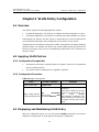
Chapter 6 VLAN Policy Configuration.........................................................................................6-1
6.1 Overview............................................................................................................................ 6-1
6.2 Applying VLAN Policies.....................................................................................................6-1
6.2.1 Configuration Prerequisites.....................................................................................6-1
6.2.2 Configuration Procedure.........................................................................................6-1
6.3 Displaying and Maintaining VLAN Policy........................................................................... 6-1
6.4 VLAN Policy Configuration Example................................................................................. 6-2
6.4.1 Network Requirements............................................................................................6-2
6.4.2 Configuration Procedure.........................................................................................6-2
Chapter 7 Traffic Mirroring Configuration..................................................................................7-1
7.1 Overview............................................................................................................................ 7-1
7.2 Configuring Traffic Mirroring to Port...................................................................................7-1
7.3 Displaying Traffic Mirroring Configuration .........................................................................7-2
7.4 Traffic Mirroring Configuration Example............................................................................7-2
7.4.1 Network Requirements............................................................................................7-2
7.4.2 Network Diagram.....................................................................................................7-2
7.4.3 Configuration Procedure.........................................................................................7-3

Operation Manual – QoS
H3C S5500-SI Series Ethernet Switches Chapter 1
QoS Overview
1-1
Chapter 1 QoS Overview
1.1 Introduction
Quality of Service (QoS) is a concept generally existing in occasions where service
supply-demand relations exist. QoS measures the ability to meet the service needs of
customers. Generally, the evaluation is not to give precise grading. The purpose of the
evaluation is to analyze the conditions where the services are good and the conditions
where the services still need to be improved, so that specific improvements can be
implemented.
In Internet, QoS measures the ability of the network to deliver packets. The evaluation
on QoS can be based on different aspects because the network provides diversified
services. Generally speaking, QoS is the evaluation on the service ability to support the
critical indexes such as delay, delay jitter and packet loss rate in packet delivery.
1.2 Traditional Packet Delivery Service
The traditional IP network treats all the packets equally. The switch adopts the first in
first out (FIFO) policy in packet processing and assigns resources necessary for packet
forwarding according to the arrival time of the packet. All the packets share the network
and router resources. The resources that the packet can get depend completely on the
chance at packets arrival.
This service policy is called Best-Effort. The switch makes its best effort to deliver the
packets to the destination but it cannot provide any guarantee for delay, delay jitter,
packet loss rate, and reliability in packet delivery.
The traditional Best-Effort service policy is only applicable to services such as WWW,
FTP, and E-mail, which are not sensitive to the bandwidth and the delay performance.
1.3 New Requirements Brought forth by New Services
With the fast development of computer networks, more and more networks are
connected into Internet. Internet extends very quickly in scale, coverage and the
number of users. More and more users use the Internet as a platform for data
transmission and develop various applications on it.
Besides traditional applications such as WWW, FTP, and E-mail, Internet users also try
to develop new services on Internet, such as tele-education, tele-medicine, video
phones, video conferencing, and video on demand (VOD). Enterprise users also hope
to connect their branch offices in different locations through the VPN technology to
develop some transaction applications, such as to access to the database of the
company or to manage remote switches through Telnet.

Operation Manual – QoS
H3C S5500-SI Series Ethernet Switches Chapter 1
QoS Overview
1-2
The new services have one thing in common: they all have special requirements for
delivery performances such as bandwidth, delay, and delay jitter. For example, video
conferencing and VOD require the guarantee of high bandwidth, low delay and low
delay jitter. Some key services such as the transaction handling and the Telnet do not
necessarily require high bandwidth but they are highly dependent on low delay and
need to be processed preferentially in case of congestion.
The emergence of new services brings forward higher requirements for the service
capability of the IP network. In the delivery process, users hope to get better services,
such as dedicated bandwidth for users, reduced packet loss rate, management and
avoidance of network congestion, control of network traffic, provision of packet priority,
and so on, instead of just having packets delivered to the destination. To meet these
requirements, the network service capability need to be further improved.
1.4 Occurrence and Influence of Congestion and the
Countermeasures
QoS issues that traditional networks face are mainly caused by congestion. Congestion
means reduced service rate and extra delay introduced because of relatively
insufficient resource provisioned.
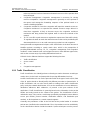
1.4.1 Occurrence of Congestion
Congestion is very common in a complicated environment of packet switching on
Internet. The diagram below gives two examples:
1000M 100M
100M
100M
10
Traffic congestion on interfaces
of different rates
Traffic conges
of the same ra
100M
0M
tion on interfaces
tes
1000M 100M
100M
100M
10
Traffic congestion on interfaces
of different rates
Traffic conges
of the same ra
100M
0M
tion on interfaces
tes
n
Figure 1-1 Traffic congestio
1) Packets enter a device over a high-speed link and are forwarded out over a
low-speed link.
2) Packets enter a device through multiple interfaces of the same rate at the same
time and are forwarded out on an interface of the same rate.
If the traffic arrives at the wire speed, the traffic will encounter the bottleneck of
resources and congestion occurs.

Operation Manual – QoS
H3C S5500-SI Series Ethernet Switches Chapter 1
QoS Overview
1-3
Besides bandwidth bottleneck, any insufficiency of resources for packet forwarding,
such as insufficiency of assignable processor time, buffer size, and memory resources
can cause congestion. In addition, congestion will also occur if the traffic that arrives
within a certain period of time is improperly controlled and the traffic goes beyond the
assignable network resources.
1.4.2 Influence of Congestion
Congestion may cause a series of negative influences:
z Congestion increases delay and delay jitter in packet delivery.
z Excessively high delay will cause retransmission of packets.
z Congestion decreases the effective throughput of the network and the utilization of
the network resources.
z Aggravated congestion will consume a large amount of network resources
(especially memory resources), and unreasonable resource assignment will even
lead to system resource deadlock and cause the system breakdown.
It is obvious that congestion is the root of service performance declination because
congestion makes traffic unable to get resources timely. However, congestion is
common in a complicated environment where packet switching and multi-user services
coexist. Therefore, congestion must be treated carefully.
1.4.3 Countermeasures
Increasing network bandwidth is a direct way to solve the problem of resource
insufficiency, but it cannot solve all the problems that cause network congestion.
A more effective way to solve network congestion problems is to enhance the function
of the network layer in traffic control and resource assignment, to provide differentiated
services for different requirements, and to assign and utilize resources correctly. In the
process of resource assignment and traffic control, the direct or indirect factors that
may cause network congestion must be properly controlled so as to reduce the
probability of congestion. When congestion occurs, the resource assignment should be
balanced according to the features and requirements of all the services to minimize the
influence of congestion on QoS.
1.5 Major Traffic Management Techniques
Traffic classification, traffic policing (TP), traffic shaping (TS), congestion management,
and congestion avoidance are the foundation for providing differentiated services. Their
main functions are as follows:
z Traffic classification: Identifies packets according to certain match rules. Traffic
classification is the prerequisite of providing differentiated services.
z TP: Monitors and controls the specifications of specific traffic entering the device.
When the traffic exceeds the threshold, restrictive or punitive measures can be

Operation Manual – QoS
H3C S5500-SI Series Ethernet Switches Chapter 1
QoS Overview
1-4
taken to protect the business interests and network resources of the operator from
being damaged.
z Congestion management: Congestion management is necessary for solving
resource competition. Congestion management is generally to cache packets in
the queues and arrange the forwarding sequence of the packets based on a
certain scheduling algorithm.
z Congestion avoidance: Excessive congestion will impair the network resources.
Congestion avoidance is to supervise the network resource usage. When it is
found that congestion is likely to become worse, the congestion avoidance
mechanism will drop packets and regulate traffic to solve the overload of the
network.
z TS: TS is a traffic control measure to regulate the output rate of the traffic actively.
TS regulates the traffic to match the network resources that can be provided by the
downstream devices so as to avoid unnecessary packet loss and congestion.
Among the traffic management techniques, traffic classification is the basis because it
identifies packets according to certain match rules, which is the prerequisite of
providing differentiated services. TP, TS, congestion management, and congestion
avoidance control network traffic and assigned resources from different approaches,
and are the concrete ways of providing differentiated services.
S5500-SI Series Ethernet Switches support the following functions:
z Traffic classification
z Access control
z TP
z Congestion management
1.5.1 Traffic Classification
Traffic classification is to identify packets conforming to certain characters according to
certain rules. It is the basis and prerequisite for proving differentiated services.
A traffic classification rule can use the precedence bits in the type of service (ToS) field
of the IP packet header to identify traffic with different precedence characteristics. A
traffic classification rule can also classify traffic according to the traffic classification
policy set by the network administrator, such as the combination of source addresses,
destination addresses, MAC addresses, IP protocol or the port numbers of the
applications. Traffic classification is generally based on the information in the packet
header and rarely based on the content of the packet. The classification result is
unlimited in range. They can be a small range specified by a quintuplet (source address,
source port number, protocol number, destination address, and destination port
number), or all the packets to a certain network segment.
Generally, the precedence of bits in the ToS field of the packet header is set when
packets are classified on the network border. Thus, IP precedence can be used directly
as the classification criterion inside the network. Queue techniques can also process

Operation Manual – QoS
H3C S5500-SI Series Ethernet Switches Chapter 1
QoS Overview
1-5
packets differently according to IP precedence. The downstream network can either
accept the classification results of the upstream network or re-classify the packets
according to its own criterion.
The purpose of traffic classification is to provide differentiated services, so traffic
classification is significant only when it is associated with a certain traffic control or
resource assignment action. The specific traffic control action to be adopted depends
on the phase and the current load status. For example, when the packets enter the
network, TP is performed on the packets according to CIR; before the packets flow out
of the node, TS is performed on the packets; when congestion occurs, queue
scheduling is performed on the packets; when congestion get worse, congestion
avoidance is performed on the packets.
1.5.2 Precedence
The following describes several types of precedence:
1) IP precedence, ToS precedence and DSCP precedence
Figure 1-2 DS field and ToS byte
As shown in the figure above, the ToS field in the IP header contains 8 bits, which are
described as follows:
The first three bits indicate IP precedence, in the value range of 0 to 7.
Bit 3 to bit 6 indicate ToS precedence, in the value range of 0 to 15.
RFC2474 re-defines the ToS field in the IP packet header, and it is called the DS field.
The first six bits in the DS field indicate DSCP precedence, in the value rang of 0 to 63.
The last two bits (bit6 and bit7) are reserved.
2) 802.1p priority
802.1p priority lies in the layer 2 packet header. It is suitable for occasions where it is
not necessary to analyze the Layer 3 packet headers and QoS is needed in Layer 2.

Operation Manual – QoS
H3C S5500-SI Series Ethernet Switches Chapter 1
QoS Overview
1-6
Figure 1-3 The format of an Ethernet frame with an 802.1Q tag header
As shown in the figure above, each host supporting 802.1Q protocol adds a 4-bit
802.1Q tag header after the source address in the original Ethernet frame header when
sending a packet.
The 4-bit 802.1Q tag header contains a 2-bit Tag Protocol Identifier (TPID) whose value
is 8100 and a 2-bit Tag Control Information (TCI). TPID is a new type defined by IEEE to
indicate a packet with a 802.1Q tag. The following figure shows the detailed contents of
an 802.1Q tag header.
Figure 1-4 The format of an 802.1Q tag header
In the figure above, the 3-bit Priority field in the TCI byte is the 802.1p priority, in the
value range of 0 to 7.These three bits represent the priority of the frame. There are a
total of eight priority levels to determine which packet is to be sent in priority when
congestion occurs to the switch. These precedence levels fall in 802.1p priority
because the applications related to these precedence levels are all defined in detail in
the 802.1p specification.
1.5.3 Introduction to TP
If the traffic from users is not limited, a large amount of continuous burst packets will
result in worse network congestion. The traffic of users must be limited in order to make
better use of the limited network resources and provide better service for more users.
For example, if a traffic flow obtains only the resources committed to it within a certain
period of time, network congestion due to excessive burst traffic can be avoided.
TP is traffic control policies to limit the traffic and its resource usage through supervision
of the traffic specification. The regulation policy is implemented according to the
evaluation result on the premise of the awareness of whether the traffic exceeds the
specification when TP is implemented. Generally, the token bucket algorithm is
adopted for the evaluation of traffic specification.

Operation Manual – QoS
H3C S5500-SI Series Ethernet Switches Chapter 1
QoS Overview
1-7
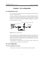
1.5.4 Traffic Evaluation and Token Bucket
I. The features of the token bucket
The token bucket can be considered as a container with a certain capacity to hold
tokens. The system puts tokens into the bucket at the set rate. When the token bucket
is full, the tokens in excess will overflow and the number of tokens in the bucket stops
increasing, as shown in
Figure 1-5.
需由此接口发送的包
继续发送
令牌桶
按规定的速率向桶内放置令
牌
分类
丢弃
Packet to be sent on this interface
Continue to send
Token bu
Put tokens into the bucket a
cket
t the set rate
Classify
Drop
需由此接口发送的包
继续发送
令牌桶
按规定的速率向桶内放置令
牌
分类
丢弃
Packet to be sent on this interface
Continue to send
需由此接口发送的包
继续发送
令牌桶
按规定的速率向桶内放置令
牌
分类
丢弃
Packet sent via this interface
Continue to send
Token bu
Put tokens into the bucket a
cket
t the set rate
Classify
Drop
需由此接口发送的包
继续发送
令牌桶
按规定的速率向桶内放置令
牌
分类
丢弃
Packet to be sent on this interface
Continue to send
需由此接口发送的包
继续发送
令牌桶
按规定的速率向桶内放置令
牌
分类
丢弃
Packet to be sent on this interface
Continue to send
Token bu
Put tokens into the bucket a
cket
t the set rate
Classify
Drop
需由此接口发送的包
继续发送
令牌桶
按规定的速率向桶内放置令
牌
分类
丢弃
Packet to be sent on this interface
Continue to send
需由此接口发送的包
继续发送
令牌桶
按规定的速率向桶内放置令
牌
分类
丢弃
Packet sent via this interface
Continue to send
Token bu
Put tokens into the bucket a
cket
t the set rate
Classify
Drop
Figure 1-5 Evaluate the traffic with the token bucket
II. Evaluate the traffic with the token bucket
The evaluation of the traffic specification is based on whether the number of tokens in
the bucket can meet the need of packet forwarding. If the number of tokens in the
bucket is enough for forwarding the packets, the traffic is compliant with the
specification; otherwise the traffic is incompliant with, or in excess of, the specification.
The parameters of token bucket for traffic evaluation include:
z Average rate: The rate at which tokens are put into the bucket, namely, the
average rate of permitted traffic flows. It is typically set to the committed
information rate (CIR).
z Burst size: The capacity of the token bucket, namely, the maximum traffic size that
is permitted in each burst. It is typically set to the committed burst size (CBS). The
set burst size must be bigger than the maximum packet length.
An evaluation is performed on the arrival of each packet. In each evaluation, if the
bucket has enough tokens for use, the traffic is controlled within the specification and a
number of tokens equivalent to the packet forwarding authority must be taken out;
otherwise, this means too many tokens have been used — the traffic is in excess of the
specification.

Operation Manual – QoS
H3C S5500-SI Series Ethernet Switches Chapter 1
QoS Overview
1-8
III. TP
A typical application of TP is to supervise the specification of a certain traffic flow into
the network and limit the specification within a reasonable range, or to punish the traffic
in excess. Thus, the network resources and the interests of the carriers are protected.
For example, you can limit the bandwidth usage of HTTP packets to 50% of the network
bandwidth. If the traffic of a certain connection is in excess, TP can choose either to
drop packets or to reset the priority of the packets.
TP is widely used in policing the traffic into the network of Internet service provider
(ISP). In addition, TP can classify the policed traffic and perform pre-defined policing
actions according to different evaluation results. These actions include:
z Forward: Forward the packets although the evaluation result is “incompliant”.
z Drop: Drop the packets whose evaluation result is “incompliant”.
z Remark the DSCP precedence and then forward: Modify the DSCP precedence of
the packets whose evaluation result is “incompliant” and then forward them.

Operation Manual – QoS
H3C S5500-SI Series Ethernet Switches Chapter 2
LR Configuration
2-1
Chapter 2 LR Configuration
2.1 Introduction to LR
You can use line rate (LR) to limit the total rate of sending packets (including emergent
packets) on a physical interface.
LR also uses token buckets for traffic control. If LR is enabled on a certain interface of
the device, all packets sent via this interface must be firstly processed in the token
bucket of LR. If the token bucket has enough tokens, the packets can be sent.
Otherwise, packets will enter QoS queues for congestion management. Thus, traffic via
this physical interface is controlled.
Packets to be sent via this interface
Packets sent
Toke
Put tokens into the b
n bucket
ucket at the set rate
Classify
Buffer
Queue
Packets to be sent via this interface
Packets sent
Toke
Put tokens into the b
n bucket
ucket at the set rate
Classify
Buffer
Queue
Figure 2-1 LR processing procedure
Because the token bucket is adopted for traffic control, when the token bucket has
tokens, burst transmission of packets is allowed; when the token bucket does not have
tokens, packets cannot be sent until new tokens are created in the token bucket. Thus,
the traffic of packets cannot be bigger than the rate of creating tokens, so the traffic is
limited and burst traffic is permitted.
Compared with TP, LR controls packets sent via physical interfaces. When you just
want to limit the rate of all packets, LR is simpler than TP.
2.2 LR Configuration
2.2.1 LR Configuration Procedure
Configuring LR is to limit the rate of outbound packets via physical interfaces.

Operation Manual – QoS
H3C S5500-SI Series Ethernet Switches Chapter 2
LR Configuration
2-2
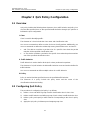
Table 2-1 LR configuration procedure
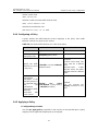
To do… Use the command… Remarks
Enter system view
system-view
—
Enter
port
view
interface interface-type
interface-number
Enter
interface
view or
port
group
view
Enter
port
group
view
port-group { manual
port-group-name |
aggregation agg-id }
Enter either view.
For Ethernet interface
view, the following
configuration takes effect
only on the current
interface. For entering port
group view, the following
configuration takes effect
on all the ports.
Set LR
qos lr outbound cir
committed-information-rate
[ cbs committed-burst-size ]
Required
Display the LR
configuration and
statistics of an
interface
display qos lr interface
[ interface-type
interface-number ]
You can execute the
display command in any
view.
2.2.2 LR Configuration Example
Limit the outbound rate of GigabitEthernet1/0/1 to 640 kbps.
# Enter system view
<H3C> system-view
# Enter interface view
[H3C] interface GigabitEthernet 1/0/1
# Configure LR parameter and limit the outbound rate to 640 kbps
[H3C-GigabitEthernet1/0/1] qos lr outbound cir 640

Operation Manual – QoS
H3C S5500-SI Series Ethernet Switches Chapter 3
QoS Policy Configuration
3-1
Chapter 3 QoS Policy Configuration
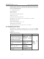
3.1 Overview
QoS policy includes the following three elements: class, traffic behavior and policy. You
can bind the specified class to the specified traffic behavior through QoS policies to
facilitate the QoS configuration.
I. Class
Class is used for identifying traffic.
The elements of a class include the class name and classification rules.
You can use commands to define a series of rules to classify packets. Additionally, you
can use commands to define the relationship among classification rules: and and or.
z and: The devices considers a packet to be of a specific class when the packet
matches all the specified classification rules.
z or: The device considers a packet be of a specific class when the packet matches
one of the specified classification rules.
II. Traffic behavior
Traffic behavior is used to define all the QoS actions performed on packets.
The elements of a QoS behavior include traffic behavior name and actions defined in
traffic behavior.
You can use commands to define multiple actions in a traffic behavior.
III. Policy
Policy is used to bind the specified class to the specified traffic behavior.
The elements of a policy include the policy name and the name of the
classification-to-behavior binding.
3.2 Configuring QoS Policy
The procedure for configuring QoS policy is as follows:
1) Define a class and define a group of traffic classification rules in class view.
2) Define a traffic behavior and define a group of QoS actions in traffic behavior view.
3) Define a policy and specify a traffic behavior corresponding to the class in policy
view.
4) Apply the QoS policy in Ethernet port view/port group view.

Operation Manual – QoS
H3C S5500-SI Series Ethernet Switches Chapter 3
QoS Policy Configuration
3-2
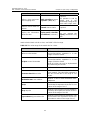
3.3 Introducing Each QoS Policy
Table 3-1 Introduce each QoS policy
Policy Class Command
Accounting
Use the if-match
match-criteria command
to define a required class
accounting
CAR (traffic policing)
Use the if-match
match-criteria command
to define a required class
car
Traffic filtering
Use the if-match
match-criteria command
to define a required class
filter
Traffic mirroring
Use the if-match
match-criteria command
to define a required class
mirror-to
Traffic redirection
Use the if-match
match-criteria command
to define a required class
redirect
Priority remark
Use the if-match
match-criteria command
to define a required class
remark
3.4 Configuring QoS Policy
3.4.1 Configuration Prerequisites
z The class name and classification rules are specified in the policy.
z The traffic behavior name and the actions in the traffic behavior are specified.
z The policy name is specified.
z Where and how to apply the policy is specified.
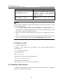
3.4.2 Defining a Class
Create a class name first and then configure match rules in this class view.
I. Configuration procedure
Table 3-2 Define a class
To do… Use the command… Remarks
Enter system view
system-view
—

Operation Manual – QoS
H3C S5500-SI Series Ethernet Switches Chapter 3
QoS Policy Configuration
3-3
To do… Use the command… Remarks
Define a class and enter
class mapping view
traffic classifier tcl-name
[ operator { and | or } ]
Required
The operator is and by
default, that is, the
relationship among all the
match rules is logic “and”.
Define a rule to match all
packets
if-match match-criteria
Required
Display the information
about the class
display traffic classifier
user-defined [ tcl-name ]
Optional
You can execute the
display command in any
view.
match-criteria: Match rule for a class, see
Table 3-3 for its range.
Table 3-3 The value range of the match rule for a class
Value Description
acl access-list-number
Defines an ACL rule. The value of the
access-list-number argument is in the
range of 2,000 to 4,999.
acl ipv6 access-list-number
Defines an IPv6 ACL rule. The value of the
access-list-number argument is in the
range of 2,000 to 3,999.
IPv6 ACL rules can only be implemented
by referencing ACL6 rules.
any
Defines a rule to match all packets
customer-vlan-id vlan-id-list
Defines a rule to match VLAN IDs of the
user network. The vlan-id-list argument is
the list of VLAN IDs in the range of 1 to
4,094.
destination-mac mac-address
Defines a rule to match destination MAC
addresses
dot1p
Defines a rule to match 802.1p protocol.
The dot1p-list argument is the list of COS
values in the range of 0 to 7.
dscp dscp-list
Defines a rule to match DSCP precedence.
The dscp-list argument is the list of DSCP
values in the range of 0 to 63.
ip-precedence ip-precedence-list
Defines a rule to match IP precedence. The
ip-precedence-list argument is the list of IP
precedence values in the range of 0 to 7.

Operation Manual – QoS
H3C S5500-SI Series Ethernet Switches Chapter 3
QoS Policy Configuration
3-4
Value Description
service-vlan-id vlan-id-list
Defines a rule to match VLAN IDs of the
operator’s network. The vlan-id-list
argument is the list of VLAN IDs in the
range of 1 to 4,094.
source-mac mac-address
Defines a rule to match source MAC
addresses
Note:
Please obey the following restrictions when defining a match rule; otherwise, you will
fail to apply the policies.
z If the customer-vlan-id, dot1p, dscp, ip-precedence or service-vlan-id is to be
matched, do not configure multiple values in a rule at the same time when you use
the if-match command to define match rules.
z When you specify the logic relationship as and, you can configure only one ACL
rule.
z When you specify the logic relationship as and, if you have configured the ACL IPv6
rule, you cannot configure other rules except if-match any at the same time.
II. Configuration example
1) Network requirements
Configure a class named “test” and define a rule to match packets whose IP
precedence is 6.
2) Configuration procedure
# Enter system view.
<H3C> system-view
# Define the class and enter class mapping view
[H3C] traffic classifier test
# Configure classification rules.
[H3C-classifier-test] if-match ip-precedence 6
3.4.3 Defining a Traffic Behavior
To define a traffic behavior, create a traffic behavior name first and then configure its
features in this traffic behavior view.

Operation Manual – QoS
H3C S5500-SI Series Ethernet Switches Chapter 3
QoS Policy Configuration
3-5
I. Configuration procedure
Table 3-4 Define a traffic behavior
To do… Use the command… Remarks
Enter system view
system-view
—
Define a traffic behavior
and enter traffic behavior
view
traffic behavior
behavior-name
Required
behavior-name: Traffic
behavior name
Configure the accounting
action
accounting
Configure to use TP
car cir
committed-information-rat
e [ cbs
committed-burst-size ]
[ red action ]
Configure the traffic
filtering action
filter { deny | permit }
Configure the traffic mirror
action
mirror-to interface-type
interface-number
Configure the traffic
redirect action
redirect interface
interface-type
interface-number
Mark the 802.1p priority of
the packet
remark dot1p dot1p
Mark the DSCP
precedence of the packet
remark dscp dscp-value
Mark the IP precedence
of the packet
remark ip-precedence
ip-precedence-value
Mark the local
precedence of the packet
remark
local-precedence
local-precedence
Required
You can configure
corresponding traffic
behaviors as required
Display the traffic
behavior information
display traffic behavior
user-defined
[ behavior-name ]
Optional
You can execute the
display command in any
view.
The red action keyword in the traffic behavior car defines some actions for the packet
not conforming to committed access rate (CAR). The action argument can be:
z discard: Drops the packet.
z pass: Forwards the packet.
z remark-dscp-pass new-dscp: Remarks the DSCP precedence of the packet and
forwards the packet to the destination address. The new-dscp argument can be
either an integer in the range of 0 to 63 or one of these keywords: af11,af12, af13,

Operation Manual – QoS
H3C S5500-SI Series Ethernet Switches Chapter 3
QoS Policy Configuration
3-6
af21, af22, af23, af31, af32, af33, af41, af42, af43, cs1, cs2, cs3, cs4, cs5, cs6,
cs7, default, and ef.
Caution:
Please obey the following restrictions when defining traffic behaviors; otherwise, you
will fail to apply the policies.
z remark dot1p and remark local-precedence cannot be configured at the same
time.
z filter deny cannot be configured together with any other action except accounting.
Note:
z When you configure the car action or accounting action in the traffic behavior, each
rule defined in traffic classification carries out the action defined in the traffic
behavior, rather than all the rules execute the same action. For example, CAR is set
to 64 kbps. For a traffic classification including 10 rules, 64 kbps is CAR for packets
matching each rule rather than the total CAR for packets matching all the ten rules.
z After traffic mirroring, packets will not go through port mirroring, that is, if you
configure the destination port of traffic mirroring as the source port of a port
mirroring group, the destination port in the port mirroring group cannot receive the
packets after traffic mirroring.
z When you configure the ingress port (it belongs to this VLAN according to the VLAN
policy) of packets as the source port of both traffic mirroring and the port mirroring
group at the same time, port mirroring configuration will be replaced by traffic
mirroring configuration. The packets matching the rule are mirrored to the
destination port of traffic mirroring, whereas the packets that do not match the rule
are mirrored to the destination port of the port mirroring group.
z Before configuring redirection, you can configure multiple STP instances. If the
home VLAN of the source port for redirection and the home VLAN of the destination
port for redirection belong to different instances, redirection will fail. The packet will
be dropped and will not be forwarded on any port.
II. Configuration example
1) Network requirements
Configure a traffic behavior named “test”, enable TP, and set committed information
rate (CIR) to 6,400 kbps.
2) Configuration procedure

Operation Manual – QoS
H3C S5500-SI Series Ethernet Switches Chapter 3
QoS Policy Configuration
3-7
# Enter system view.
<H3C> system-view
# Define a traffic and enter traffic behavior view
[H3C] traffic behavior test
# Define the classification rule.
[H3C-behavior-test] car cir 6400
3.4.4 Configuring a Policy
A policy defines the traffic-behavior–to-class mappings in the policy. Each traffic
behavior consists of a group of QoS actions.
Table 3-5 Specify the traffic behavior for a class in the policy
To do… Use the command… Remarks
Enter system view
system-view
—
Define a policy and
enter policy view
qos policy policy-name —
Specify the traffic
behavior for a class
in the policy
classifier tcl-name behavior
behavior-name
Required
tcl-name: Class name. The
class must be a defined
class.
behavior-name: Traffic
behavior name. The traffic
behavior must be a defined
traffic.
Display the
configuration
information of the
specified classes in
the specified policy
and the
configuration
information of traffic
behaviors
associated with
these classes.
display qos policy
user-defined [ policy-name ]
[ classifier tcl-name ]
Optional
You can execute the
display command in any
view.
3.4.5 Applying a Policy
I. Configuration procedure
Use the qos apply policy command to map a policy to the specified port. A policy
mapping can be applied to multiple ports or port groups.

Operation Manual – QoS
H3C S5500-SI Series Ethernet Switches Chapter 3
QoS Policy Configuration
3-8
Table 3-6 Apply a policy on the port
To do… Use the command… Remarks
Enter system view
system-view
—
Enter port view
interface interface-type
interface-number
Enter
port
view or
port
group
view
Enter port group
view
port-group { manual
port-group-name |
aggregation agg-id }
One of them is
required.
In Ethernet port view,
the following
configuration takes
effect only on the
current port. In port
group view, the
following configuration
takes effect on all the
ports in the port group.
Apply the associated policy
qos apply policy
policy-name inbound
Required
Display the configuration
information and running
status of the policy on the
specified port or all the ports
display qos policy
interface [ interface-type
interface-number ]
[ inbound ]
Display the configuration
information of the specified
class or all classes in the
specified policy or all
policies and the
configuration information of
the behavior(s) associated
with the class(es)
display qos policy
user-defined
[ policy-name ] [ classifier
tcl-name ]
Optional
You can execute the
display command in
any view.
Caution:
When the configured policy is applied to a port group, if the car or accounting action is
not included in the user-defined traffic behavior, the policy of multiple ports occupies
only one share of hardware resource, that is, resource multiplexing is implemented. If
the car action or accounting action is included in the user-defined traffic behavior, the
policy will occupy n shares of hardware resources, where n is the number of ports in the
port group.
II. Configuration example
1) Network requirements
Page is loading ...
Page is loading ...
Page is loading ...
Page is loading ...
Page is loading ...
Page is loading ...
Page is loading ...
Page is loading ...
Page is loading ...
Page is loading ...
Page is loading ...
Page is loading ...
Page is loading ...
Page is loading ...
Page is loading ...
-
 1
1
-
 2
2
-
 3
3
-
 4
4
-
 5
5
-
 6
6
-
 7
7
-
 8
8
-
 9
9
-
 10
10
-
 11
11
-
 12
12
-
 13
13
-
 14
14
-
 15
15
-
 16
16
-
 17
17
-
 18
18
-
 19
19
-
 20
20
-
 21
21
-
 22
22
-
 23
23
-
 24
24
-
 25
25
-
 26
26
-
 27
27
-
 28
28
-
 29
29
-
 30
30
-
 31
31
-
 32
32
-
 33
33
-
 34
34
-
 35
35


H3C S5500-SI Series Operating instructions
- Type
- Operating instructions
Ask a question and I''ll find the answer in the document
Finding information in a document is now easier with AI
Related papers
-
H3C S5500-SI Series Operating instructions
-
H3C s5820x series Configuration manual
-
-
-
H3C WX5002 Configuration manual
-
-
-
-
-
H3C LSUM1WCME0 User Configuration Manual
Other documents
-
Dahua DH-S5500-24GF4XF-E User manual
-
Cisco ASR 9000 Series Service Configuration Manual
-
RCA THOMSON SpeedTouchTM (Wireless) Business DSL Router User manual
-
Cisco Systems QC-29 User manual
-
-
HP 1920-24G-PoE+ User manual
-
Huawei V200R001 User manual
-
LG ES-2010G User manual
-
Juniper EX9200 Series Features Manual
-
3com Router 3035 User manual