Grundfos CR 64 Installation And Operating Instructions Manual
- Type
- Installation And Operating Instructions Manual

CR, CRI, CRN
Installation and operating instructions
GRUNDFOS INSTRUCTIONS

English (GB)
2
English (GB) Installation and operating instructions
Original installation and operating instructions
These installation and operating instructions
describe Grundfos CR, CRI and CRN pumps, 0.37 -
75 kW.
Sections 1-4 give the information necessary to be
able to unpack, install and start up the product in a
safe way.
Sections 5-10 give important information about the
product, as well as information on service, fault
finding and disposal of the product.
CONTENTS
Page
1. General information
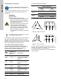
1.1 Hazard statements
The symbols and hazard statements below may
appear in Grundfos installation and operating
instructions, safety instructions and service
instructions.
The hazard statements are structured in the
following way:
1.2 Notes
The symbols and notes below may appear in
Grundfos installation and operating instructions,
safety instructions and service instructions.
1. General information
2
1.1 Hazard statements
2
1.2 Notes
2
2. Receiving the product
3
2.1 Transporting the product
3
2.2 Unpacking the product
3
2.3 Inspecting the product
3
2.4 Lifting the product
3
3. Installing the product
4
3.1 Mechanical installation
4
3.2 Electrical connection
10
4. Starting up the product
12
4.1 Shaft seal run-in
12
4.2 Frequency of starts and stops
13
4.3 Operating the product
13
5. Product introduction
14
5.1 Identification
14
5.2 Intended use of the product
15
6. Servicing the product
15
6.1 Contaminated products
16
6.2 Service documentation
16
6.3 Maintaining the product
16
7. Taking the product out of operation
18
7.1 Frost protection
18
7.2 Taking the product permanently out of
operation
18
8. Fault finding the product
19
9. Technical data
21
9.1 Operating conditions
21
9.2 Electrical data
23
9.3 Dimensions and weights
23
10. Disposing of the product
23
Read this document before installing the
product. Installation and operation must
comply with local regulations and accepted
codes of good practice.
DANGER
Indicates a hazardous situation which, if
not avoided, will result in death or serious
personal injury.
WARNING
Indicates a hazardous situation which, if
not avoided, could result in death or
serious personal injury.
CAUTION
Indicates a hazardous situation which, if
not avoided, could result in minor or
moderate personal injury.
SIGNAL WORD
Description of hazard
Consequence of ignoring the warning.
- Action to avoid the hazard.
Observe these instructions for explosion-
proof products.
A blue or grey circle with a white graphical
symbol indicates that an action must be
taken.
A red or grey circle with a diagonal bar,
possibly with a black graphical symbol,
indicates that an action must not be taken
or must be stopped.
If these instructions are not observed, it
may result in malfunction or damage to the
equipment.
Tips and advice that make the work easier.

English (GB)
3
2. Receiving the product
2.1 Transporting the product
2.2 Unpacking the product
2.3 Inspecting the product
Before you install the product, do the following:
1. Check that the product is as ordered.
2. Check that no visible parts have been damaged.
If parts are damaged or missing, contact your local
Grundfos sales company.
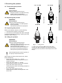
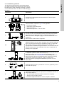
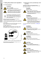
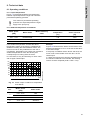
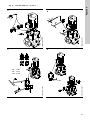
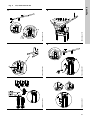
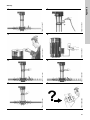
2.4 Lifting the product
When lifting the entire product with motor, follow
these instructions:
• Pump with motor sizes 0.37 - 5.5 kW:
Lift the pump in the motor flange by means of
straps or the like.
• Pump with motor sizes 7.5 - 22 kW:
Lift the pump by means of the motor eyebolts.
• Pump with motor sizes 30-45 kW:
Lift the pump by means of the lifting brackets on
the motor flange.
• Pump with motor sizes 55-75 kW:
Lift the pump by means of the eyebolts on the
motor side.
Fig. 1 Lifting points
In case of CR, CRI and CRN pumps with other
motors than MG or Siemens, we recommend that
you lift the pump by means of the straps in the motor
flange.
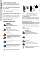
WARNING
Falling objects
Death or serious personal injury
- Keep the product in a stable and fixed
position during transportation.
- Wear personal protective equipment.
WARNING
Falling objects
Death or serious personal injury
- Keep the product in a stable position
during unpacking.
- Wear personal protective equipment.
WARNING
Falling objects
Death or serious personal injury
- Follow the lifting instructions.
- Use lifting equipment which is approved
for the weight of the product.
- Persons must keep a safe distance to
the product during lifting operations.
- Wear personal protective equipment.
Note that typically the centre of gravity of
the pump is close to the motor.
0.37 - 5.5 kW 7.5 - 22 kW
TM04 0339 0608
TM04 0341 0608
30-45 kW 55-75 kW
TM05 9564 4113
TM04 0341 0608

English (GB)
4
3. Installing the product
3.1 Mechanical installation
3.1.1 Lifting the product
For lifting instructions, see section 2.4 Lifting the
product.
WARNING
Contamination when pumping drinking
water
Death or serious personal injury
- Before the pump is used for supplying
drinking water, flush the pump
thoroughly with clean water.
- Do not use the pump for drinking water
if the internal parts have been in contact
with particles or substances not suitable
for water intended for human
consumption.
WARNING
Falling objects
Death or serious personal injury
- Follow the lifting instructions.
- Use lifting equipment which is approved
for the weight of the product.
- Persons must keep a safe distance to
the product during lifting operations.
- Wear personal protective equipment.

English (GB)
5
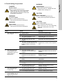
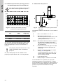
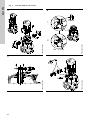
3.1.2 Installation guidelines
The pump must be secured to a horizontal, plane
and solid foundation with bolts through the holes in
the base plate. When installing the pump, be aware
of the information below in order to avoid damaging
the pump.
Illustration Information
1
TM02 0013 3800
Arrows on the pump base show the direction of flow of liquid
through the pump.
2
TM00 2256 3393
This information is stated in fig. 3 in the appendix:
• port-to-port lengths
• dimensions of the base plate
• pipe connections
• diameter and position of anchor bolts.
3
TM01 1241 4097
You can install the pump vertically or horizontally. CR, CRN 120
and 150, 75 kW, only vertically. However, the motor must neither
fall below the horizontal plane nor be installed upside down.
Make sure that an adequate supply of cool air reaches the motor
cooling fan.
Motors above 4 kW must be supported.
3a
TM05 7705 1013
Additional support. As the centre of gravity of the pump is relatively
high, we recommend that pumps installed on ships, in areas with
risk of earth quake or in systems which can be moved, are
equipped with an additional support bracket. You can fit the bracket
from the motor stool to the bulkhead of the ship, a rigid wall in a
building or to a rigid part.
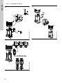
4
TM02 0116 3800
To minimise possible noise from the pump, we recommend that you
fit expansion joints on either side of the pump.
Build a foundation and carry out mechanical installation as
described in section 3.1.3 Foundation. Fit the isolating valves on
either side of the pump to avoid draining the system if the pump
needs to be removed for cleaning, repair or replacement.
Always protect the pump against backflow by means of a non-
return valve.
5
TM02 0114 3800
Install the pipes so that air pockets do not occur, especially on the
inlet side of the pump.
6
TM02 0115 3800
Fit a vacuum valve close to the pump if the installation has one of
these characteristics:
• The outlet pipe slopes downwards away from the pump.
• There is a risk of siphon effect.
• Protection against backflow of unclean liquids is needed.
2
1
2
1
L
L
B
4 x ø
B

English (GB)
6
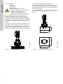
3.1.3 Foundation
We recommend that you install the pump on a
concrete foundation which is heavy enough to
provide permanent and rigid support for the entire
pump. The foundation must be capable of absorbing
any vibration, normal strain or shock. The concrete
foundation must have an absolutely level and even
surface.
Place the pump on the foundation, and fasten it. The
base plate must be supported on the whole area.
The following instruction applies when mounting the
pump in both vertical and horizontal position. Place
the pump on the foundation, and fasten it. See fig. 2.
Fig. 2 Correct installation
The recommended length and width of the
foundation are shown in fig. 3. Note that for pumps
with motor size below or equal to 30 kW, the length
and width of the foundation must be 200 mm larger
than the base plate.
For pumps with motor size equal to 37 kW or above,
the length and width must always be 1.5 x 1.5 (Lf x
Bf) m.
Fig. 3 Foundation, vertical mounting
WARNING
Falling objects
Death or serious personal injury
- Keep the product in a stable and fixed
position before installing it.
- Make sure that the foundation is
suitable for the weight of the product.
TM04 0342 0608
TM04 0343 0608

English (GB)
7
The foundation length and width must always be 200
mm larger than the length and width of the pump.
See fig. 4.
Fig. 4 Foundation, horizontal mounting
The mass of the foundation must be at least 1.5
times the total mass of the pump. The minimum
height of the foundation (hf) can then be calculated:
The density (δ) of concrete is usually taken as 2200
kg/m
3
.
In installations where noise-less operation is
particularly important, we recommend that you use a
foundation with a mass up to 5 times that of the
pump.
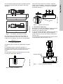
The foundation must be provided with anchor bolts
for fixing the base plate. See fig. 5.
Fig. 5 Bolt in foundation
When the anchor bolts are in position, place the
pump on the foundation. Then align the base plate
using shims, if necessary, so that it is completely
horizontal. See fig. 6.
Fig. 6 Alignment with shims
3.1.4 Vibration dampening
Elimination of noise and vibrations is best achieved
by means of a concrete foundation, vibration
dampers and expansion joints.
If you use vibration dampers, install them under the
foundation. For pumps with motor size below or
equal to 30 kW, you can use vibration dampers as
shown in fig. 7.
For pumps with motor sizes equal to 37 kW or above,
use a Sylomer
®
plate as shown in fig. 8.
Fig. 7 Pump on vibration dampers
TM05 9579 4113
hf =
Mpump × 1.5
Lf × Bf × δconcrete
TM03 4589 2206
TM04 0362 0608TM04 1691 1008
Shims
Vibration dampers

English (GB)
8
Fig. 8 Pump on Sylomer
®
plate
3.1.5 Outdoor installation
When the pump is installed outdoors, we recommend
that you provide the motor with a rain cover. We also
recommend that you open one of the drain holes in
the motor flange.
3.1.6 Tightening torques
The table shows the recommended torques for base
plate anchor bolts and flange bolts.
The bolt quality must be minimum class 8.8.
3.1.7 Flange forces and torques
If not all loads reach the maximum permissible value
stated in the tables below, one of these values may
exceed the normal limit. Contact Grundfos for further
information.
Fig. 9 Flange forces and torques
The following tables represent the values that apply
according to the material quality.
TM04 1692 1008
WARNING
Flange gasket blowout
Death or serious personal injury
- Tighten flange bolts according to the
torque values stated in the installation
and operating instructions.
CR,
CRI,
CRN
Base
[Nm]
Flange bolts [Nm]
Bolt
size
DIN, JIS,
ANSI
Oval
1s-5 40 M10 - 50-60
10-20 50 M12 60 60-70
32-150 70
M16 100 70-80
M20 150 -
M24 200 -
Sylomer
®
plate
TM04 0346 2013
Y-direction: Inlet or outlet
Z-direction: Direction of chamber stack
X-direction: 90 ° from inlet or outlet

English (GB)
9
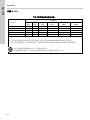
Force limits
Torque limits
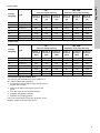
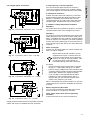
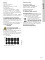
3.1.8 Positioning the terminal box
You can turn the terminal box to four positions, in
90 ° steps. Follow this procedure:
1. If necessary, remove the coupling guards. Do not
remove the coupling.
2. Remove the bolts securing the motor to the
pump.
3. Turn the motor to the required position.
4. Replace and tighten the bolts.
5. Replace the coupling guards.
Carry out the electrical connection as shown in the
diagram inside the terminal box cover.
Flange,
DN [mm]
Type
CR -
Cast iron pump housing
CRI, CRN -
Stainless steel pump housing
Force, Y-
direction
[N]
Force, Z-
direction
[N]
Force, X-
direction
[N]
Force, Y-
direction
[N]
Force, Z-
direction
[N]
Force, X-
direction
[N]
25/32 1s-5 338 394 319 675 788 638
40 10 413 469 375 825 938 750
50 15 and 20 563 581 506 1125 1163 1013
65 32 694 788 638 1388 1575 1275
80 45 938 769 844 1875 1538 1688
100 64 and 90 1256 1013 1125 2513 2025 2250
125/150 120 and 150 1256 1013 1125 2513 2025 2250
Flange,
DN [mm]
Type
CR -
Cast iron pump housing
CRI, CRN -
Stainless steel pump housing
Torque, Y-
direction
[Nm]
Torque, Z-
direction
[Nm]
Torque, X-
direction
[Nm]
Torque, Y-
direction
[Nm]
Torque, Z-
direction
[Nm]
Torque, X-
direction
[Nm]
25/32 1s-5 300 175 125 600 350 250
40 10 400 275 200 800 550 400
50 15 and 20 450 325 250 900 650 500
65 32 500 350 300 1000 700 600
80 45 325 400 550 650 800 1100
100 64 and 90 375 475 625 750 950 1250
125/150 120 and 150 375 475 625 750 950 1250

English (GB)
10
3.2 Electrical connection
The electrical connection must be carried out by an
authorised electrician in accordance with local
regulations.
The operating voltage and frequency are marked on
the motor nameplate. Make sure that the motor is
suitable for the power supply on which it is used and
that the motor terminal connection is correct. You will
find a wiring diagram in the terminal box.
3.2.1 Cable entry/screwed connection
All motors are supplied without screwed cable
entries. The table below shows the numbers and
sizes of cable entry holes of the terminal box
according to the standard EN 50262.
3.2.2 Three-phase connection
1)
60 Hz motors, 0.37 - 1.1 kW: 220-277/380-440 V.
Fig. 10 Delta connection
Fig. 11 Star connection
If the motor is provided with PTC sensors or PTO
contacts, the connection must be in accordance with
the wiring diagram in the terminal box.
Connect three-phase motors to a motor-protective
circuit breaker.
Follow the instructions for the motor when
carrying out the electrical connections.
WARNING
Electric shock
Death or serious personal injury
- Before starting any work on the product,
make sure that the power supply has
been switched off and that it cannot be
accidentally switched on.
- Connect the pump to an external main
switch close to the pump and to a
motor-protective circuit breaker or a
CUE frequency converter. Make sure
you can lock the main switch in OFF
position (isolated). Type and
requirements as specified in EN 60204-
1, 5.3.2.
Consider whether it is necessary to install
an emergency stop switch.
Motor
[kW]
Number and
size of cable
entries
Description
0.25-
0.55
2 x M20 x 1.5
The holes have precast
threads and are closed
with knock-out cable
entries.
0.75-
3.0
2 x M20
The holes are closed
with knock-out cable
entries.
4.0-
7.5
4 x M25
The holes are closed
with knock-out cable
entries.
11-22
2 x M20
4 x M40
The holes are closed
with knock-out cable
entries.
30-45 2 x M50 x 1.5 Blanking plug.
55-75 2 x M63 x 1.5 Blanking plug.
Mains supply [V]
Delta
connection
Star
connection
50 Hz
220-240 / 380-415
380-415 / 660-690
60 Hz
220-277 / 380-480
1)
380-480 / 660-690
TM02 6656 1305TM02 6655 1305
W2 U2 V2
U1 V1 W1
U1
U2
V1
V2
W1
W2
L
3
L
2
L
1
W2
U2
V2
U1
U1
V1
V1
W1
U2
V2
W1
W2
L
3
L
2
L
1

English (GB)
11
3.2.3 Single-phase connection
Fig. 12 Connection, 220-230 V, 0.37 - 0.75 kW
Fig. 13 Connection, 240 V, 0.37 - 0.75 kW
Fig. 14 Connection, 220-230 V, 1.1 - 2.2 kW
Fig. 15 Connection, 240 V, 1.1 - 2.2 kW
Single-phase Grundfos motors incorporate a thermal
switch and require no additional motor protection.
3.2.4 Frequency converter operation
You can use three-phase motors for frequency
convertor operation following the conditions below.
This section applies to motors defined in IEC 60034.
3.2.5 General conditions
Protect all motors used with frequency converters
against voltage peaks and dU/dt according to IEC
60034-17. Grundfos recommends that you use
insulated bearings for motors from frame size 225
(45 kW/2-pole, 30 kW/4-pole and 22 kW/6-pole).
3.2.6 Mains voltage dependent conditions
200-240 V
No output filters are required for frequency converter
operated motors with mains voltages up to 240 V.
380-500 V
For frequency converter operated motors with power
cable length less than 25 m and mains supply up to
460 V, no additional motor protection against voltage
peaks is required. For frequency converter operated
motors with power cable length of more than 25 m or
mains supply higher than 460 V, sine-wave filters are
required.
500 V and higher
Always use sine-wave filters for motors marked with
500 V or higher voltages.
Exception
• Protect Grundfos motors types MG 71 and MG
80 (up to 1.1 kW/2-pole and up to 0.75 kW/4-
pole) for supply voltages up to and including 440
V without phase insulation against voltage peaks
above 650 V between the supply terminals.
• If you use MG 71 and MG 80 without phase
insulation for input voltages above 240 V, it
requires that you use sine-wave filters at the
output of the frequency converter.
MG 71 and MG 80 with phase insulation for use with
variable frequency drives are available as standard
products.
Motors supplied by Grundfos
You can connect all three-phase MG motors with
phase insulation to a frequency converter.
Other motor makes than those supplied by
Grundfos
Contact Grundfos or the motor manufacturer.
TM04 1693 1008TM04 1694 1008TM04 0345 0608TM04 0344 0608
Motors with reinforced insulation can be
supplied as an option. These motors are
according to IEC 60034-25 and therefore
there is no need for sine-wave filters. This
do not eliminate the requirement for
insulated bearings from frame size 225.

English (GB)
12
3.2.7 Phase insulation, MG 71 and 80
MG motors, frame sizes 71 and 80, do not have
phase insulation as standard. The motors are not
suitable for frequency converter operation as they
are not protected against the voltage peaks caused
by the frequency converter operation. Only motors
with a rated voltage equal to 460 V or above have
phase insulation.
We recommend that you protect all other motors
against voltage peaks higher than 1200 V by 2000 V/
μsec.
You can eliminate the above disturbances, that is
both increased acoustic noise and detrimental
voltage peaks, by fitting an LC filter between the
frequency converter and the motor.
For further information, contact the frequency
converter or motor supplier.
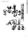
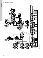
4. Starting up the product
Fig. 16 Vent valve, standard and an optional
solution with hose connection
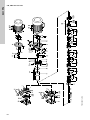
Follow the startup instructions in the appendix.
CR, CRI, CRN 1s to 5
For these pumps, we recommend that you open the
bypass valve during startup. See fig. 18 for bypass
valve location. The bypass valve connects the inlet
and outlet sides of the pump, thus making the filling
procedure easier. Close the bypass valve again
when the operation is stable.
When pumping liquids containing air, we recommend
that you leave the bypass valve open if the operating
pressure is lower than 6 bar.
Close the bypass valve if the operating pressure
constantly exceeds 6 bar. Otherwise, the material at
the opening will be worn because of the high liquid
velocity.
4.1 Shaft seal run-in
Frequency converter operation of MG
motors without phase insulation will cause
damage to the motor.
WARNING
Corrosive liquids
Death or serious personal injury
- Wear personal protective equipment.
WARNING
Toxic liquids
Death or serious personal injury
- Wear personal protective equipment.
CAUTION
Hot or cold liquid
Minor or moderate personal injury
- Wear personal protective equipment.
- Pay attention to the direction of the vent
hole when you fill the pump with liquid
and vent it.
- Make sure that no persons are hurt by
the escaping liquid.
Fill the pump with liquid and vent it before
you start the pump.
Pay attention to the direction of the vent
hole during liquid filling and venting. Make
sure that the escaping liquid does not
cause damage to the motor or other
components.
If the pump runs dry, the pump bearings
and the shaft seal may be damaged.
TM05 1160 0611 - TM05 8098 1913
WARNING
Corrosive liquids
Death or serious personal injury
- Wear personal protective equipment.
WARNING
Toxic liquids
Death or serious personal injury
- Wear personal protective equipment.
CAUTION
Hot or cold liquid
Minor or moderate personal injury
- Wear personal protective equipment.
Make sure that a leakage does not cause
damage to the equipment.

English (GB)
13
The seal faces are lubricated by the pumped liquid,
meaning that there may be a certain amount of
leakage from the shaft seal.
When you start the pump for the first time, or when
you install a new shaft seal, a certain run-in period is
required before the leakage is reduced to an
acceptable level. The time required for this depends
on the operating conditions, that is every time the
operating conditions change, a new run-in period will
be started.
Under normal conditions, the leaking liquid will
evaporate. As a result, no leakage will be detected.
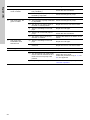
4.2 Frequency of starts and stops
4.3 Operating the product
For operating the product safely, observe the
following hazard statements:
See fig. 4 in the appendix.
Hot or cold surfaces
Figure 17 shows which pump parts get as hot or cold
as the pumped liquid.
Fig. 17 Hot or cold surfaces on a CR, CRI and
CRN pump
For motor bearing maintenance at ambient
temperatures above 40 °C, see section
10. Disposing of the product.
Motor size
[kW]
Maximum number of starts per
hour
0.37 - 2.2 250
3-4 100
5.5 - 11 50
18.5 - 22 40
30 90
37 50
45 80
55 50
75 50
WARNING
Contamination when pumping drinking
water
Death or serious personal injury
- Do not use the pump for drinking water
if the internal parts have been in contact
with particles or substances not suitable
for water intended for human
consumption.
WARNING
Airborne noise
Death or serious personal injury
- Wear personal protective equipment.
WARNING
Too high pressure and leakage
Death or serious personal injury
- Do not run the pump against a closed
outlet valve.
CAUTION
Hot or cold surface
Minor or moderate personal injury
- Make sure that no one can accidentally
come into contact with hot or cold
surfaces.
CAUTION
Hot or cold liquid
Minor or moderate personal injury
- Wear personal protective equipment.
TM04 0361 0608
Pump head
Pump sleeve
Base

English (GB)
14
5. Product introduction
5.1 Identification
5.1.1 Type key for CR, CRI, CRN 1s, 1, 3, 5, 10, 15 and 20
5.1.2 Type key for CR, CRN 32, 45, 64, 90, 120 and 150
Example CR 3- 10 X- X- X- X- XXXX
Type range: CR, CRI, CRN
Rated flow rate in m
3
/h
Number of impellers
Code for pump version
Code for pipe connection
Code for materials
Code for rubber pump parts
Code for shaft seal
Example CR 32- 2 1- X- X- X- X- XXXX
Type range: CR, CRN
Rated flow rate in m
3
/h
Number of stages
Number of impellers with reduced diameter
Code for pump version
Code for pipe connection
Code for materials
Code for rubber pump parts
Code for shaft seal

English (GB)
15
5.2 Intended use of the product
Only use the CR, CRI and CRN pumps according to
the specification stated in these installation and
operating instructions.
5.2.1 Applications
Grundfos multistage in-line centrifugal pumps, types
CR, CRI and CRN, are designed for a wide range of
applications.
CR, CRI, CRN
CR, CRI and CRN pumps are suitable for liquid
transfer, circulation and pressure boosting of cold or
hot clean liquids.
CRN
Use CRN pumps in systems where all parts in
contact with the liquid are made of high-grade
stainless steel.
5.2.2 Pumped liquids
CR, CRI and CRN pump are suitable for pumping
thin, clean, non-flammable, non-combustible or non-
explosive liquids, not containing solid particles or
fibres.
When pumping liquids with a density and/or viscosity
higher than that of water, use motors with
correspondingly higher outputs, if required.
6. Servicing the product
For lifting instructions, see section 2.4 Lifting the
product.
DANGER
Fire and explosion
Death or serious personal injury
- Do not use the pump for flammable,
combustible or explosive liquids.
WARNING
Chemical attack and leakage
Death or serious personal injury
- Do not use the pump for liquids which
can attack the pump materials
chemically.
- Contact Grundfos if in doubt.
WARNING
Corrosive liquids
Death or serious personal injury
- Wear personal protective equipment.
WARNING
Toxic liquids
Death or serious personal injury
- Wear personal protective equipment.
CAUTION
Hot or cold liquid
Minor or moderate personal injury
- Wear personal protective equipment.
DANGER
Electric shock
Death or serious personal injury
- Before starting any work on the product,
make sure that the power supply has
been switched off and that it cannot be
accidentally switched on.
WARNING
Falling objects
Death or serious personal injury
- Follow the lifting instructions.
- Use lifting equipment which is approved
for the weight of the product.
- Persons must keep a safe distance to
the product during lifting operations.
- Wear personal protective equipment.
WARNING
Falling objects
Death or serious personal injury
- Keep the product in a stable and fixed
position when working on it.
WARNING
Corrosive liquids
Death or serious personal injury
- Wear personal protective equipment.
WARNING
Toxic liquids
Death or serious personal injury
- Wear personal protective equipment.
WARNING
Contamination when pumping drinking
water
Death or serious personal injury
- Before the pump is used for supplying
drinking water, flush the pump
thoroughly with clean water.
- Do not use the pump for drinking water
if the internal parts have been in contact
with particles or substances not suitable
for water intended for human
consumption.
- Always use original spare parts suitable
for drinking water.

English (GB)
16
We recommend that you repair pumps with motors of
7.5 kW and above at the installation site. Necessary
lifting equipment must be available.
6.1 Contaminated products
The product will be classified as contaminated if it
has been used for a liquid which is injurious to health
or toxic.
If you request Grundfos to service the product,
contact Grundfos with details about the liquid before
returning the product for service. Otherwise,
Grundfos can refuse to accept the product for
service.
Any application for service must include details
about the liquid.
Clean the product in the best possible way before
you return it.
Costs of returning the product are to be paid by the
customer.
6.2 Service documentation
6.2.1 Pump
Service documents and service kits are available in
Grundfos Product Center (http://product-
selection.grundfos.com).
6.2.2 Motor
Grundfos motors
Service documentation is available in Grundfos
Product Center (http://product-
selection.grundfos.com/).
If you have any questions, please contact the
nearest Grundfos company or service workshop.
Other motors makes than MG
Contact the motor manufacturer.
6.3 Maintaining the product
CAUTION
Hot or cold liquid
Minor or moderate personal injury
- Wear personal protective equipment.
CAUTION
Hot or cold surface
Minor or moderate personal injury
- Make sure that no one can accidentally
come into contact with hot or cold
surfaces.
CAUTION
Biological hazard
Minor or moderate personal injury
- Flush the product thoroughly with water
and rinse the product parts in water
after dismantling.
DANGER
Electric shock
Death or serious personal injury
- Before starting any work on the product,
make sure that the power supply has
been switched off and that it cannot be
accidentally switched on.
WARNING
Falling objects
Death or serious personal injury
- Follow the lifting instructions.
- Use lifting equipment which is approved
for the weight of the product.
- Persons must keep a safe distance to
the product during lifting operations.
- Wear personal protective equipment.

English (GB)
17
For lifting instructions, see section 2.4 Lifting the
product.
6.3.1 Pump
The pump bearings and the shaft seal are
maintenance-free.
6.3.2 Motor
Carry out maintenance as described in the
instructions for the motor which are supplied with the
pump.
Motor bearings
Motors not fitted with grease nipples are
maintenance-free.
Motors fitted with grease nipples must be lubricated
with a high-temperature, lithium-based grease. See
the instructions on the fan cover.
In the case of seasonal operation where the motor is
idle for more than 6 months of the year, we
recommend that you grease the motor when you
take the pump out of operation.
Depending on the ambient temperature, replace or
lubricate the motor bearings according to the table
below. The table applies to 2-pole motors. The
number of operating hours stated for bearing
replacement are guidelines only.
Intervals for 4-pole motors are twice as long as those
for 2-pole motors.
If the ambient temperature is lower than 40 °C, then
replace or lubricate the bearings at the intervals
mentioned under 40 °C.
WARNING
Falling objects
Death or serious personal injury
- Keep the product in a stable and fixed
position when working on it.
WARNING
Corrosive liquids
Death or serious personal injury
- Wear personal protective equipment.
WARNING
Toxic liquids
Death or serious personal injury
- Wear personal protective equipment.
CAUTION
Hot or cold liquid
Minor or moderate personal injury
- Wear personal protective equipment.
CAUTION
Hot or cold surface
Minor or moderate personal injury
- Make sure that no one can accidentally
come into contact with hot or cold
surfaces.
Motor
size
[kW]
Bearing replacement interval
[operating hours]
40 °C 45 °C 50 °C 55 °C 60 °C
0.37-
0.75
18000 - - - -
1.1-
7.5
20000 15500 12500 10000 7500
Motor
size
[kW]
Lubrication interval [operating hours]
40 °C 45 °C 50 °C 55 °C 60 °C
11-
18.5
4500 3400 2500 1700 1100
22 4000 3100 2300 1500 1000
30-55 4000 3000 2000 1500 -
75 2000 1500 1000 500 -

English (GB)
18
7. Taking the product out of operation
7.1 Frost protection
Drain pumps which are not being used during
periods of frost to avoid damage.
To drain the pump loosen the vent screw in the pump
head and remove all drain plugs from one side of the
pump base.
Do not tighten the vent screw and replace the drain
plug until the pump is to be used again.
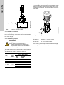
CR, CRI, CRN 1s to 5
Before replacing the drain plug in the base, screw
the bypass valve out against the stop. See fig. 18.
Fig. 18 Location of drain plug and bypass valve
Fit the drain plug by tightening the large union nut
followed by the bypass valve.
7.2 Taking the product permanently out of
operation
Observe the following if the pump is to be
permanently taken out of operation and removed
from the pipe system.
For lifting instructions, see section 2.4 Lifting the
product.
CAUTION
Hot or cold liquid
Minor or moderate personal injury
- Pay attention to the direction of the vent
hole and drain plug when draining the
pump. Make sure that the escaping
liquid does not cause injury to persons.
- Wear personal protective equipment.
Pay attention to the direction of the vent
hole and drain plug when draining the
pump. Make sure that the escaping liquid
does not cause damage to the motor or
other components.
TM01 1243 4097
Drain plug
Bypass valve
DANGER
Electric shock
Death or serious personal injury
- Before starting any work on the product,
make sure that the power supply has
been switched off and that it cannot be
accidentally switched on.
WARNING
Falling objects
Death or serious personal injury
- Follow the lifting instructions.
- Use lifting equipment which is approved
for the weight of the product.
- Persons must keep a safe distance to
the product during lifting operations.
- Wear personal protective equipment.
WARNING
Falling objects
Death or serious personal injury
- Keep the product in a stable and fixed
position when working on it.
WARNING
Corrosive liquids
Death or serious personal injury
- Wear personal protective equipment.
WARNING
Toxic liquids
Death or serious personal injury
- Wear personal protective equipment.
CAUTION
Hot or cold liquid
Minor or moderate personal injury
- Wear personal protective equipment.
CAUTION
Hot or cold surface
Minor or moderate personal injury
- Make sure that no one can accidentally
come into contact with hot or cold
surfaces.

English (GB)
19
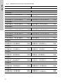
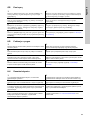
8. Fault finding the product
DANGER
Electric shock
Death or serious personal injury
- Before starting any work on the product,
make sure that the power supply has
been switched off and that it cannot be
accidentally switched on.
WARNING
Corrosive liquids
Death or serious personal injury
- Wear personal protective equipment.
WARNING
Toxic liquids
Death or serious personal injury
- Wear personal protective equipment.
WARNING
Falling objects
Death or serious personal injury
- Keep the product in a stable and fixed
position when working on it.
CAUTION
Hot or cold liquid
Minor or moderate personal injury
- Wear personal protective equipment.
CAUTION
Hot or cold surface
Minor or moderate personal injury
- Make sure that no one can accidentally
come into contact with hot or cold
surfaces.
Fault Cause Remedy
1. The motor does not run
when started.
a) Supply failure. Connect the power supply.
b) The fuses are blown. Replace fuses.
c) The motor-protective circuit
breaker has tripped.
Reactivate the motor-protective
circuit breaker.
d) The thermal protection has
tripped.
Reactivate the thermal protection.
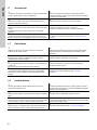
e) The main contacts in the motor-
protective circuit breaker are not
making contact or the coil is
faulty.
Replace the contacts or the magnetic
coil.
f) The control circuit is defective. Repair the control circuit.
g) The motor is defective. Replace the motor.
2. The motor-protective
circuit breaker trips
immediately when the
power supply is
switched on.
a) One fuse is blown or the
automatic circuit breaker has
tripped.
Replace the fuse or cut in the circuit
breaker.
b) The contacts in the motor-
protective circuit breaker are
faulty.
Replace the motor-protective circuit
breaker contacts.
c) The cable connection is loose or
faulty.
Fasten or replace the cable
connection.
d) The motor winding is defective. Replace the motor.
e) The pump is mechanically
blocked.
Remove the mechanical blocking of
the pump.
f) The motor-protective circuit
breaker setting is too low.
Set the motor-protective circuit
breaker correctly.
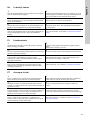
3. The motor-protective
circuit breaker trips
occasionally.
a) The motor-protective circuit
breaker setting is too low.
Set the motor-protective circuit
breaker correctly.
b) Low voltage at peak times. Ensure a stable power supply.
4. The motor-protective
circuit breaker has not
tripped, but the pump
does not run.
a) See 1 a), b), d), e) and f).

English (GB)
20
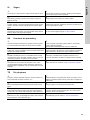
5. The pump performance
is not constant.
a) The pump inlet pressure is too
low (cavitation).
Check the inlet conditions.
b) The inlet pipe or pump is partly
blocked by impurities.
Clean the inlet pipe or pump.
c) The pump draws in air. Check the inlet conditions.
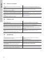
6. The pump runs, but
gives no water.
a) The inlet pipe or pump is blocked
by impurities.
Clean the inlet pipe or pump.
b) The foot or non-return valve is
blocked in closed position.
Repair the foot or non-return valve.
c) There is a leakage in the inlet
pipe.
Repair the inlet pipe.
d) There is air in the inlet pipe or
pump.
Check the inlet conditions.
e) The motor runs in the wrong
direction of rotation.
Change the direction of rotation of the
motor.
7. The pump runs
backwards when
switched off.
a) There is a leakage in the inlet
pipe.
Repair the inlet pipe.
b) The foot or non-return valve is
defective.
Repair the foot or non-return valve.
8. Leakage in shaft seal. a) The shaft seal is defective. Replace the shaft seal.
9. Noise. a) Cavitation. Check the inlet conditions.
b) The pump does not rotate freely
due to frictional resistance as a
result of incorrect pump shaft
position.
Adjust the pump shaft.
Follow the procedure in fig. 6, 7, 8 or
9 in the appendix.
c) Frequency converter operation. See section 3.2.4 Frequency
converter operation.
Fault Cause Remedy
Page is loading ...
Page is loading ...
Page is loading ...
Page is loading ...
Page is loading ...
Page is loading ...
Page is loading ...
Page is loading ...
Page is loading ...
Page is loading ...
Page is loading ...
Page is loading ...
Page is loading ...
Page is loading ...
Page is loading ...
Page is loading ...
Page is loading ...
Page is loading ...
Page is loading ...
Page is loading ...
Page is loading ...
Page is loading ...
Page is loading ...
Page is loading ...
Page is loading ...
Page is loading ...
Page is loading ...
Page is loading ...
Page is loading ...
Page is loading ...
Page is loading ...
Page is loading ...
Page is loading ...
Page is loading ...
Page is loading ...
Page is loading ...
Page is loading ...
Page is loading ...
Page is loading ...
Page is loading ...
Page is loading ...
Page is loading ...
Page is loading ...
Page is loading ...
Page is loading ...
Page is loading ...
Page is loading ...
Page is loading ...
Page is loading ...
Page is loading ...
Page is loading ...
Page is loading ...
Page is loading ...
Page is loading ...
Page is loading ...
-
 1
1
-
 2
2
-
 3
3
-
 4
4
-
 5
5
-
 6
6
-
 7
7
-
 8
8
-
 9
9
-
 10
10
-
 11
11
-
 12
12
-
 13
13
-
 14
14
-
 15
15
-
 16
16
-
 17
17
-
 18
18
-
 19
19
-
 20
20
-
 21
21
-
 22
22
-
 23
23
-
 24
24
-
 25
25
-
 26
26
-
 27
27
-
 28
28
-
 29
29
-
 30
30
-
 31
31
-
 32
32
-
 33
33
-
 34
34
-
 35
35
-
 36
36
-
 37
37
-
 38
38
-
 39
39
-
 40
40
-
 41
41
-
 42
42
-
 43
43
-
 44
44
-
 45
45
-
 46
46
-
 47
47
-
 48
48
-
 49
49
-
 50
50
-
 51
51
-
 52
52
-
 53
53
-
 54
54
-
 55
55
-
 56
56
-
 57
57
-
 58
58
-
 59
59
-
 60
60
-
 61
61
-
 62
62
-
 63
63
-
 64
64
-
 65
65
-
 66
66
-
 67
67
-
 68
68
-
 69
69
-
 70
70
-
 71
71
-
 72
72
-
 73
73
-
 74
74
-
 75
75


Grundfos CR 64 Installation And Operating Instructions Manual
- Type
- Installation And Operating Instructions Manual
Ask a question and I''ll find the answer in the document
Finding information in a document is now easier with AI
Related papers
-
Grundfos CRI Series Installation And Operating Instructions Manual
-
Grundfos CRT 8 Installation And Operating Instructions Manual
-
Grundfos CRT Installation And Operating Instructions Manual
-
Grundfos CR 64 Installation And Operating Instructions Manual
-
-
-
-
-
Grundfos MQ 3-45 Installation guide
-
Other documents
-
Watts MQ3-45 Installation guide
-
Electrolux FCG202 Datasheet
-
Mountfield S 390 E Owner's manual
-
 Verdero VF80 User manual
-
Brinkmann BE1530 Operating instructions
-
Sartorius TopMix TM01-Y Installation Instructions Manual
-
BETCO BPS26 Owner's manual
-
Senco SCN125 User manual
-
sauermann Si-1830 Installation guide
-
Beta 1569/A Operating instructions
