Page is loading ...

IS-SS-Manifolds
Installation Instructions
Stainless Steel Manifolds
WARNING
!
Read this Manual BEFORE using this equipment.
Failure to read and follow all safety and use information
can result in death, serious personal injury, property
damage, or damage to the equipment.
Keep this Manual for future reference.
Watts Stainless Steel Manifolds offer great
features for centralizing plumbing connections
and controls.
• Flexible, modular, and singular design system
• Easy-to-assemble construction
• Precise flow control and balancing
• Fittings for both PEX and Onix radiant tubing
• Control for hydronic floor, fan coil, or baseboard heating
• No sealant, no PTFE tape
The manifolds are sold in 1 to 12 branch pairs for easy assembly
in the field. Constructed with 1" AISI 304 Stainless Steel, these
distribution units can handle up to 12 gallons per minute. The
manifold sections connect easily when more circuits are required.
Simply thread two sections together by using a 1" manifold
coupling and tighten. Install the gasket before assembly.
Manifolds Are Sold in Pairs
Balancing Valve Manifold (with optional Actuator)
Flow Indicator Manifold
Accessories
Add-ons include Vent/Purge Assembly, Valve Actuator,
Transitional Fittings, Mounting Brackets (standard with manifold
pairs), and Lockable Manifold Boxes (Vent/Purge, End Caps,
Trunk Isolation Valves, and Transition Fittings all have flat gaskets
that must be installed without the use of sealants or PTFE tape.)
Flow Balancing
Balancing is achieved by either one of two methods:
• Using the Balance Valve Adjustment Knob
• Using the Valve Flow Adjustment Key to change the dial
located under the adjustment knob (The key comes attached
to the manifold with a nylon tie.)
Flow can be visually fine-tuned by viewing the sight glass
indicator while adjusting the balancing valve on the return
manifold.
On/Off Circuit Control
For systems requiring individual circuit thermostatic control,
install the optional circuit actuator. Valve actuators are four-
wire devices, to connect to the zone thermostat and use end
switch wires to activate the circulator. With this arrangement,
each room can be thermostatically controlled from one central
distribution manifold.
NOTICE
Depending on the actuator style in use, some circuit adjustment
may be necessary.
Additional flow control can be achieved by installing individual
circuit isolation mini-ball valves. These valves allow for balancing
and shutoff capabilities without having to remove the adjustment
cap or thermal actuator.
Manifolds are not intended to exceed 87 psi at 194°F operating
conditions.
ITEM NUMBER DESCRIPTION
D3803002SS M2 Stainless Steel Manifold Pair with Flow Meters
D3803003SS M3 Stainless Steel Manifold Pair with Flow Meters
D3803004SS M4 Stainless Steel Manifold Pair with Flow Meters
D3803005SS M5 Stainless Steel Manifold Pair with Flow Meters
D3803006SS M6 Stainless Steel Manifold Pair with Flow Meters
D3803007SS M7 Stainless Steel Manifold Pair with Flow Meters
D3803008SS M8 Stainless Steel Manifold Pair with Flow Meters
D3803009SS M9 Stainless Steel Manifold Pair with Flow Meters
D3803010SS M10 Stainless Steel Manifold Pair with Flow Meters
D3803011SS M11 Stainless Steel Manifold Pair with Flow Meters
D3803012SS M12 Stainless Steel Manifold Pair with Flow Meters
D4201720-P Trunk Isolation Ball Valve with Temperature Gauge
D4201715-N Vent and Purge Assembly
D063064-N Manifold End Cap
D4201480-P BSP to NPT Transition Fitting
D402178-P 1" x 1" Manifold Coupling
Note:
- Order T-20 Compression PEX fittings or Onix fittings and clamps separately.
- Stainless steel manifolds can be ordered fully assembled.
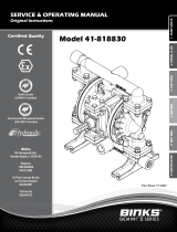
Optional Circuit Actuator
Typical Manifold Assembly

The manual vent at the top of
the Vent/Purge assembly uses
a directional discharge cap. Turn
the white cap to aim the pressure
discharge.
The Vent/Purge assembly incor-
porates a built-in purge valve.
Open the valve by loosening the
lower nut. To close the valve,
tighten the lower nut.
Do not adjust the Attachment
Nut, as this part removes the
valve from the assembly.
When tightening the compression nut,
hold the base firmly with a thin profile box
wrench. Do not let the base nut tighten or
loosen while adjusting the compression fit.
Tighten the compres-
sion nut to 20 inch-
pounds of torque.
If without a torque
wrench, tighten the nut
until snug then make an
additional quarter turn.
NOTE: The compression sleeve is “directional.”
It is barbed on the inside to help lock the
PEX in place. Slide the sleeve onto the PEX
so the groove on the outside of the sleeve is
closest to the insert fitting.
Attachment Nut
Purge Open/Close
Manual Key Vent
Gasket
2"
L
41⁄2"
11⁄16"
17⁄16"
25⁄8"
115⁄16"
23⁄16"
Valve Flow
Adjustment Key
Mounting Bracket
Flow Indicator
Balance Valve
Adjustment Knob
Circuit Mini-
Ball Valve
End Cap Gasket
Circuit Isolation Plug
Replace Flow Indicator
with Isolation Plug
Vent/Purge Assembly
Trunk Isolation Valve with
Temperature Gauge
Gasket BSP (straight thread)
3/4" BSP Connection to
PEX or Onix Fittings
Gaskets must be installed.
PTFE tape or thread sealants not required.
Circuit Isolation Cap
Ensure the O-ring is in
place for a proper seal.
Manifold Size 2345678910 11 12
Length (L) inches 7.28 9.25 11.22 13.19 15.16 17.13 19.09 21.06 23.03 25.00 26.97
Limited Warranty: Watts Regulator Co. (the “Company”) warrants each product to be free from defects in material and workmanship under normal usage for a period of one year from the date of
original shipment. In the event of such defects within the warranty period, the Company will, at its option, replace or recondition the product without charge.
THE WARRANTY SET FORTH HEREIN IS GIVEN EXPRESSLY AND IS THE ONLY WARRANTY GIVEN BY THE COMPANY WITH RESPECT TO THE PRODUCT. THE COMPANY MAKES NO OTHER
WARRANTIES, EXPRESS OR IMPLIED. THE COMPANY HEREBY SPECIFICALLY DISCLAIMS ALL OTHER WARRANTIES, EXPRESS OR IMPLIED, INCLUDING BUT NOT LIMITED TO THE IMPLIED
WARRANTIES OF MERCHANTABILITY AND FITNESS FOR A PARTICULAR PURPOSE.
The remedy described in the first paragraph of this warranty shall constitute the sole and exclusive remedy for breach of warranty, and the Company shall not be responsible for any incidental, special
or consequential damages, including without limitation, lost profits or the cost of repairing or replacing other property which is damaged if this product does not work properly, other costs resulting
from labor charges, delays, vandalism, negligence, fouling caused by foreign material, damage from adverse water conditions, chemical, or any other circumstances over which the Company has no
control. This warranty shall be invalidated by any abuse, misuse, misapplication, improper installation or improper maintenance or alteration of the product.
Some States do not allow limitations on how long an implied warranty lasts, and some States do not allow the exclusion or limitation of incidental or consequential damages. Therefore the above
limitations may not apply to you. This Limited Warranty gives you specific legal rights, and you may have other rights that vary from State to State. You should consult applicable state laws to
determine your rights. SO FAR AS IS CONSISTENT WITH APPLICABLE STATE LAW, ANY IMPLIED WARRANTIES THAT MAY NOT BE DISCLAIMED, INCLUDING THE IMPLIED WARRANTIES OF
MERCHANTABILITY AND FITNESS FOR A PARTICULAR PURPOSE, ARE LIMITED IN DURATION TO ONE YEAR FROM THE DATE OF ORIGINAL SHIPMENT.
IS-SS-Manifolds 2305 81021304 © 2023 Watts
USA: T: (800) 276-2419 • Watts.com
Canada: T: (905) 332-4090 • Watts.ca
Latin America: T: (52) 55-4122-0138 • Watts.com
/