Page is loading ...

Construction
Automotive
Industry
www.rehau.com
REHAU RADIANT HEATING SYSTEMS
INSTALLATION GUIDE

2
Table of Contents
1. Scope . . . . . . . . . . . . . . . . . . . . . . . . . . . . . . . . . . . . . . . . . . . . . . . . . . . 3
2. Installation Considerations. . . . . . . . . . . . . . . . . . . . . . . . . . . . . . . . . . . 4
3. Installation Overview .......................................5
4. System Component Overview ................................6
5. Preparing for Installation ....................................7
6. Installing Manifolds .......................................11
7. Connecting Pipes to Manifolds ............................... 13
8. Handling Pipe . . . . . . . . . . . . . . . . . . . . . . . . . . . . . . . . . . . . . . . . . . . . 14
9. Installing Pipe in Floor, Wall or Ceiling .........................18
10. Testing the System. . . . . . . . . . . . . . . . . . . . . . . . . . . . . . . . . . . . . . . . 26
11. Pouring Slab or Overpour ................................... 28
12. Completing the Finished Covering ............................30
13. Starting the System .......................................33
This symbol and the signal words DANGER, WARNING or CAUTION alert you
to personal injury hazards. If you don’t avoid the hazardous situation:
– DANGER! Will result in death or serious injury
– WARNING! Could result in death or serious injury
– CAUTION! Can result in minor or moderate injury
The signal word NOTICE is used to help you avoid property damage. We
cannot warn of all hazards; you must also use your own good judgment.
For updates to this publication and the most current REHAU technical guidelines,
safety information and manufacturer's recommendations, visit
na.rehau.com/resourcecenter

3
1. SCOPE
This technical information applies to the installation, testing and operation of
REHAU radiant heating systems using PEXa crosslinked polyethylene pipe.
Persons using this guide must be experienced and appropriately licensed hydronic
heating system installers, who have an understanding of the principles and prac-
tices for hydronic installations.
The information presented in this guide is intended to demonstrate general
methods and is not specic to your project conditions. It is the responsibility of the
installer to check the prevailing local codes and to verify that technical information
presented in this guide is appropriate for a particular installation. This guide does
not supersede the recommendations of other manufacturers. If there is conicting
information, the installer must consult with the other manufacturer or manufactur-
er's representative prior to installing, connecting and operating the REHAU radiant
heating system.
After reading this guide, the installer should attend the appropriate REHAU Academy
seminar, where installation techniques for radiant heating systems are more fully
explored.
This guide assumes the installer has already been provided with a REHAU radiant
heating system design or approved equivalent in accordance to the REHAU Radiant
Heating Systems Design Guide. This guide should be used in conjunction with the
REHAU Sustainable Building Technology Product Catalog which provides a detailed
description of each system component. The installer should also review the REHAU
PEXa Limited Warranty and pertinent supplemental REHAU Technical Bulletins be-
fore beginning to install a radiant heating system. Installers should also periodically
check the REHAU Resource Center for the latest updates.
If you do not have prior experience with hydronic heating systems or require ad-
ditional assistance, please contact your regional REHAU sales representative.

4
2. INSTALLATION CONSIDERATIONS
The following points should be considered when installing a radiant heating system:
– Do not proceed with the installation without a radiant heating design. Failure
to install in accordance to a well-planned design may result in poor system
performance.
– Do not proceed with the installation without a piping layout. The pipe layout
drawing shows the manifold location(s) and the location and length of each
radiant heating circuit. Without a well-planned layout, you can waste signicant
time and money.
– Verify the manifold location(s) are agreed to by the designer, general contractor
and building owner, and comply with local codes.
– Follow other manufacturers’ recommendations and guidelines. Failure to do so
may result in noise and nished covering damage.
– Do not store pipe outdoors or where exposed to sunlight. Keep pipe in original
protective packaging until ready to install. Minimize UV exposure during instal-
lation.
− Do not install pipe outdoors above the ground unless permanently and properly
protected from exposure to sunlight.
– Do not hang manifolds crooked or without brackets.
– Do not mix up supply and return tails when connecting to the manifold. Do
not lose track of which pipe corresponds to each circuit. Use the REHAU
PRO-BALANCE
®
Manifold Circuit Chart.
– Do not cut pipe with a saw blade or pocket knife.
– Do not let pipe oat close to the surface when pouring a slab or overpour. Do not
let nylon ties oat to the surface. Clip and remove excess tie ends.
– Do not install pipe with spacing between pipes greater than shown in the design,
as this could result in cold spots.
– Do not nail, staple or screw through the pipe.
– Do not exceed temperature limits of nished covering, slab, overpour or suboor.
Floor, wall and ceiling coverings can be damaged by excessive temperatures
leading to discoloring, noise, delaminating, warping, cracking and deterioration of
the nished coverings.
– Wear safety shoes, gloves, glasses and hearing protection when appropriate.
Wear suitable clothes and follow all safety regulations.

5
3. INSTALLATION OVERVIEW
The following sequence is the most efcient way to install the REHAU radiant
heating system:
1. Gather and review documents
2. Prepare and inspect job site
3. Install manifold
4. Install pipe and connect to manifold
5. Perform system air pressure test
6. Pour slab or overpour if required
7. Insulate below suboor or suspended slab if required
8. Install nished coverings
9. Connect manifold to distribution piping and heat source
9. Flush, ll and purge the system with heating uid
10. Adjust the system ow rates
Fig. 3.1: Typical REHAU radiant heating system installation.
RAUPEX
®
pipe (1); PRO-BALANCE manifold (2)
2
1

6
4. SYSTEM COMPONENTS OVERVIEW
REHAU offers pipes, ttings, manifolds, heat transfer panels and plates, controls,
and a variety of installation accessories and tools. For a detailed description of our
system components, refer to the REHAU Sustainable Building Technology Product
Catalog.
– RAUPEX O
2
Barrier and RAUPEX SPEED
™
Pipe
– PRO-BALANCE Manifolds, Connectors and Accessories and Copper Manifolds
– RAUPANEL
™
and RAUBOARD
™
Heat Transfer Panels
– RAUPEX SPEED Mat
– RAUPLATE
™
and Heavy Gauge Heat Transfer Plates
– REHAU Smart Controls
– Zone Controls, Thermostats and Other Controls
– EVERLOC+
™
Compression-sleeve Fittings, F2080 Compression-sleeve Fittings
and Other RAUPEX Fittings and Valves
– EVERLOC+ Compression-sleeve Tools, F2080 Compression-sleeve Tools and
Other Installation Tools
– Installation Accessories and Other Hydronic Accessories

7
5. PREPARING FOR INSTALLATION
If there are potential problems with the design and/or job site construction that
could affect the quality of the radiant heating installation or system performance,
notify the appropriate designer, contractor(s) or owner immediately.
5.1 Reviewing Local Codes
The installer is responsible for checking with applicable code authorities to deter-
mine specic local code requirements.
5.2 Gathering Documents
The radiant heating system design should be complete before attempting installa-
tion. You should have the details for the oor, wall and ceiling construction and the
schedule outlining manifold size(s) and pipe size, spacing and circuit lengths for
each heated area. Building drawings may also be necessary before proceeding with
your installation.
5.3 Inspecting the Job Site
Before beginning the installation, you should perform a site inspection.
1. Familiarize yourself with the installation sequence and scheduling for the con-
struction of the building.
Changes in the construction schedule may be required to ensure the integrity of
your installation. REHAU recommendeds that other construction that might in-
terfere with the pipe installation (e.g., drywall, plumbing) is not scheduled during
your installation. Make sure that any other work that is to follow the installation
of the radiant heating system will not damage the system components.
2. Conrm that the job site as-built matches your building plans or drawings.
Check for anything that might interfere with pipe installation such as changes to
concrete walls or footings and changes to the layout of walls or oors. Note any
changes; a redesign of the pipe layout might be required.
If pipes are to pass into rooms through doorways or follow along walls that are
not yet installed, we recommend that you use the building plans to measure and
mark their planned locations with paint or wood studs. These “virtual” walls will
act as a guide when installing pipe.

8
3. Inspect the condition of the building site.
Inspect the site for possible hazards that could damage RAUPEX pipe, such as
nails, staples, materials or tools from other trades, or chemicals that could spill
and damage the pipe. Eliminate potential hazards before installing pipe.
Conrm that the additional oor height for overpour and heat transfer panel
construction has been taken into account. Door moldings, base plates and
electrical outlets may need to be raised. Doors, thresholds and stairs may need
to be modied.
Conrm the sub-grade for the heated areas has been properly prepared. It
should be level, compacted and drained. If required, ensure the vapor barrier
and insulation are installed and per local code.
Ensure the existing suboor or slab for heated areas is at, level, structurally
sound, free of noise and debris before installing pipe.
A typical overpour thickness adds 13 to 17 lb/ft (63 to 80 kg/m) “dead load” to
a suspended oor structure. Conrm the oor structure has been approved to
carry this weight by an architect or engineer.
Correct any discrepancies before installing pipe.
5.4 Checking the Design
It is the full responsibility of the installer to thoroughly review the design documents
and determine the suitability of the plans for the installer's intended use prior to
ordering materials and installing the system.
1. Check the manifold locations are correct (see Section 6.1)
2. Check the orientation of the pipes in the layout is correct (see Section 9.2)
3. Check the circuit lengths are not too long (see Section 9.4)
4. Check the nished oor coverings are per the design (see Section 12.1)

9
Fig. 5.1: RAUPEX horizontal uncoiler
Fig. 5.2: RAUPEX universal uncoiler
REHAU tools provide fast, easy, professional installations and are required to as-
semble REHAU compression-sleeve ttings to RAUPEX pipes. It is important to use
a proper cutter when cutting RAUPEX pipes. A clean, square cut is required.
Refer to the REHAU F2080 Compression Sleeve Product Instructions for the F2080
compression-sleeve tools.
Refer to the REHAU EVERLOC+ Assembly Product Instructions for EVERLOC+
compression-sleeve tools.
5.5 Organizing the Tools
Typical construction tools are required to complete a radiant heating system
installation.
REHAU uncoilers speed the RAUPEX pipe installation.

10
5.6 Storing and Delivering System Components
RAUPEX pipe is shipped in a cardboard box or opaque plastic bag that offers extra
protection from sunlight, rain, dirt and other hazards. Keep pipe in the box or bag
until it is required for installation, and return unused pipe to the protective packag-
ing. REHAU’s PEXa pipes must not be stored outdoors and are not designed for per-
manent outdoor installation (with the exception of non-exposed buried applications).
Refer to REHAU Technical Bulletin 218 for the accumulated maximum UV exposure
periods. Failure to follow recommendations for maximum UV exposure could result
in premature pipe failure and will negate the REHAU PEXa Limited Warranty.
REHAU ttings, manifolds, accessories and tools should be stored in a dry location.
To avoid denting and damage, store in a location with minimal trafc. Do not stack
heavy materials on top of REHAU components.
To improve the ease of installation in cold weather below 40°F (5°C), REHAU
recommends storing pipe at room temperature for a few hours before installation.
Extra care should be taken when bending cold pipe to avoid kinking.
Normal methods of packaging and protection should be exercised when shipping
and handling to prevent damage from dents, dings, abrasion, crushing and other
hazards.

11
6. INSTALLING MANIFOLDS
Refer to the REHAU PRO-BALANCE Manifold Product Instructions for the installation
and operation of this manifold.
REHAU recommends installing the manifold before installing the pipe. Connect each
circuit as it is installed to avoid mixing up circuits or supply and return tails.
6.1 Best Practice for Manifold Locations
The pipe layout drawing should show the manifold location and the layout and
length of each pipe circuit to the heated areas.
Verify that manifold location is agreed to by the builder and owner. Location should
be easily accessible to facilitate installation of the RAUPEX pipe, the distribution
supply and return pipes from the heat source, wiring from thermostats to connect
to circuit actuators (if used), and for any future servicing requirements.
Manifolds should be centrally located within the heated areas for easier pipe
routing. Common locations include mechanical rooms, closets, cabinets or crawl
spaces. We recommend that manifolds be located in a heated space, but not within
an outside wall or building panel. Manifolds must be installed in a non-corrosive
environment.
Manifolds can be mounted within a stud wall and may require installation of an
access panel for later servicing.
Carefully choose the location for the manifold. Performing system pressure tests,
lling the system with uid and purging air can sometimes result in uids being
spilled in the area near the manifold.
Fig. 6.1: 1 in. PRO-BALANCE manifold

12
6.2 PRO-BALANCE Manifold Installation
REHAU recommends when using an air test to slightly wet the at gaskets with
water during assembly of the manifold. Install the manifold in the location indicated
on the plans or pipe layout drawing.
REHAU steel manifold cabinets are typically used in industrial, institutional and
commercial installations, or where required.
Fig. 6.2: PRO-BALANCE ush cabinet
for brass manifolds
Fig. 6.3: PRO-BALANCE surface cabinet
for brass manifolds
The manifold should be securely mounted, either horizontally or vertically, in its
nal position. If the permanent structure does not exist (common in slab-on-grade
installations), you may have to build a temporary manifold support from wood studs
or rebar driven into the sub-grade.
Position the manifold a minimum of 16 in (40 cm) above nished oor level. A
height of 36 in (90 cm) to the top of the manifold will usually allow for convenient
pipe connections and future servicing. Make sure that the manifold is level.
Protect the manifold from damage and vandalism during and after construction.
For temporary placements, an empty RAUPEX pipe box, placed over the installed
manifold, provides some protection against weather and dirt.
The manifold should remain accessible for service after completion of the project.
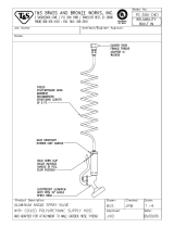
6.3 Installing Protective Bend Guides Between Manifold and Slab
or Overpour
REHAU recommends the use of pipe protection where RAUPEX pipe enters the slab
or overpour at the base of a manifold. PVC bend guides hold the pipe in a 90° bend
and protect the pipe from damage by the concrete contractors and oor nishers.
To install PVC bend guides, simply in-
sert RAUPEX pipe through the guide to
the appropriate length, usually 20-30 in
(50 -75 cm) of pipe on the other side.
The guide should be positioned so that
the pipe rises straight to the manifold
and so that half the guide will be within
the thermal mass.
Fig. 6.4: PVC bend guides transition pipes
90° from manifold to horizontal slab

13
7. CONNECTING PIPES TO MANIFOLDS
After the manifold is securely mounted in its nal position, you can begin connect-
ing the RAUPEX pipe. Connect each pipe to the manifold as it is being installed.
Attach the pipe to the upper supply header rst, passing it behind the lower return
header.
Fig. 7.1: R-20 compression tting for
connecting RAUPEX to PRO-BALANCE
manifold
Fig. 7.2: Installing pipe to manifold with
R-20 connector
1. Cut the pipe to length so there will be no stress on the manifold connection.
Make sure that the pipe is cut squarely. Attach the manifold connector to the end
of the RAUPEX pipe. When using 3/4 in. RAUPEX manifold connectors, attach
the manifold connector bushing to the manifold outlet with the hex end of the
bushing closest to the header. Thread sealant is not required.
2. Place the pipe end with attached connector up to the appropriate manifold outlet.
3. Hand-tighten the manifold compression nut connection. If the tting is aligned
properly, it will go on smoothly. Thread sealant is not required.
4. Once the compression nut connection is hand tight, use a 1 1/4 in (32 mm)
wrench on the compression nut and do not turn more than one-half turn. (Use
a 1 1/2 in [38 mm] wrench for 3/4 in. RAUPEX manifold connectors.) Do not
over tighten, as this may destroy the integral O-ring. You may wish to tighten all
ttings at the same time once all pipes are connected.
5. All compression nut connections must be inspected for leakage after several
hours of operation. Compression nuts may need to be tightened. Do not turn
more than one-half turn. (Use a 1 1/2 in [38 mm] wrench for 3/4 in. RAUPEX
manifold connectors.) Do not over tighten, as this may destroy the integral
O-ring.
Note: After tightening, if the compression nut does not seal, remove connection and
pipe from the manifold, cut off the small section of pipe where the split ring was
and remake the connection. Before cutting the pipe, ensure there is adequate slack
in the pipe to allow for the new connection.

14
8. HANDLING PIPE
When handling RAUPEX pipe, it is important to avoid:
– Dragging it over rough objects such as gravel or concrete
– Crushing it by driving overtop with wheelbarrow or power equipment
– Contact with oil or oily products (e.g., gasoline, paint thinner)
– Soldering operations or any open ame
– Excessive exposure to sunlight as per the allowable exposure time
8.1 Uncoiling Pipe
The uncoiler should be located in an area that will not interfere with the installation.
First, carefully cut the outer binding strings of the coiled pipe. When working with
1,000 ft (305 m) coils, cut only the outer binding strings at rst. This will release
approximately half the pipe for uncoiling.
An uncoiling device such as the RAUPEX uncoiler makes it easy to unwind a pipe
coil. If you don’t have an uncoiler, have one person hold the pipe coil off the ground
between their arms while another person pulls pipe from the top or the bottom of
the coil. RAUPEX should not be pulled off of a coil that is lying at on the ground.
Occasional twisting in the pipe may occur during installation, particularly when
installing without the benet of an uncoiler. This must be corrected before installing
additional pipe. If the pipe becomes twisted, simply rotate the coil 90° or more, in
the direction of the twist, until the pipe lays at.
8.2 Bending Pipe
RAUPEX pipe may be bent, even when cold. The minimum bend radius is 5X the OD
for cold bends. For an even smaller bend radius, the pipe may be heated with a hot
air gun and bent to no less than 3X the OD.
REHAU support bends make it fast and easy to create tight bends without kinking,
such as where the pipe rises out of a slab or overpour straight up to the manifold.
Pipe Size
Nominal Cold Bend Heated Bend
in in (mm) in (mm)
3/8 2.5 (64) 1.5 (38)
1/2 3.125 (79) 1.875 (48)
5/8 3.75 (95) 2.25 (57)
3/4 4.375 (111) 2.625 (67)
1 5.625 (143) 3.375 (86)
Table 8.1: Minimum 90° Bend Radius of RAUPEX Pipe

15
Pipe Size Minimum Loop Diameter = Minimum Pipe Spacing
Nominal Cold Loop Heated Loop
in. in. (mm) in. (mm)
3/8 5.0 (128) 3.0 (72)
1/2 6.25 (158) 3.75 (56)
5/8 7.5 (190) 4.5 (114)
3/4 8.75 (222) 5.25 (134)
1 11.25 (246) 6.75 (172)
Bend Diameter = 2X Bend Radius = 180° Loop
When pipes are laid out in parallel, the minimum pipe spacing is determined by the
minimum bend radius shown in Table 8.1.
Table 8.2: Minimum Parallel Pipe Spacing
8.3 Connecting Two Pipes
REHAU compression-sleeve ttings are designed for use with RAUPEX pipe and
should only be assembled with REHAU tools.
Refer to the REHAU F2080 Compression-sleeve Product Instructions for the
assembly of F2080 compression-sleeve ttings.
Refer to the REHAU EVERLOC+ Assembly Product Instructions for the assembly of
EVERLOC+ compression-sleeve ttings.

16
8.4 Burying Pipe Connections in a Slab or Overpour
REHAU permits the use of REHAU compression-sleeve joints to be buried in a
concrete slab or gypsum cement overpour or buried underground in soil.
Compression nut and threaded adapter ttings are intended to transition RAUPEX
pipe to the building service piping and should be accessible for periodic inspection.
NOTICE: REHAU recommends that threaded connections should not be buried.
Operational failure or expensive repair costs can result if a leak develops from a
buried threaded connection.
Fig. 8.3: OK to bury compression
sleeve connections
Fig. 8.4: Do not bury threaded
connections
OK
X
Burial of a compression-sleeve joint requires that:
– Joint must be encased in RAUCROSS
™
Heat Shrink sleeving or a waterproof
rubber tape.
– The location of each joint should be marked on the “as-built” drawings.
– The installer should visually inspect each joint prior to burial.
– A system pressure test must be performed prior to and during the pour.
– Verify that these instructions comply with local codes.
Applying RAUCROSS Heat Shrink
1. Use the appropriate size of
RAUCROSS from the REHAU
Sustainable Building Technology
Product Catalog.
2. Cut RAUCROSS to length. There
should be at least 1 in (25 mm) of
overlap past the tting.
3. Slide RAUCROSS over the end of the pipe.
4. Connect pipes with compression-sleeve joint.
5. Slide RAUCROSS back over the tting, ensuring that there is adequate overlap.
6. Using a hot air gun, apply heat to RAUCROSS. Rotate heat gun around the tting
while moving along its length to ensure even shrinkage. As soon as RAUCROSS
has shrunk evenly along its entire length, remove heat.
Applying Waterproof Rubber Tape
1. Use the waterproof rubber tape from the REHAU Sustainable Building Technology
Product Catalog or an approved equivalent.
2. Apply two layers of tape. There should be at least 1 in (25 mm) of overlap past
the tting.
Fig. 8.5: F2080 compression-sleeve
joint protected by RAUCROSS heat
shrink
OK

17
8.5 Repairing Kinked Pipe
RAUPEX pipe is exible and resists kinking even at temperatures well below freez-
ing. If the pipe becomes kinked due to excessive bending, ow may be obstructed
or reduced. Kinked pipe must be repaired.
You can straighten the pipe by simply heating the area with a hot air gun. Rotate
the heat gun around the pipe to evenly heat the surface. Always use caution when
operating a heat gun and never use a torch or open ame to heat the pipe.
When fully heated, the pipe will get soft. When the kink is gone, turn off the heat
gun and let the area cool. (It is normal for small bubbles or wrinkles to appear
on red or blue pipe.) This type of heating will anneal or stiffen the pipe, making it
stronger but also less exible in the heated area. Therefore, do not try to bend the
pipe in the same spot. This may require a slight adjustment of fasteners so that the
previously kinked section of pipe is installed without being bent.
8.6 Replacing Damaged Pipe
If the pipe is damaged, it might need to be replaced. Cut out the damaged area and
connect the pipes with REHAU compression-sleeve joint. In some cases it may be
necessary to use two couplings and additional pipe to replace the damaged area.
Follow the instructions in Section 8.3 Connecting Two Pipes.
A scrape in the oxygen diffusion barrier of RAUPEX O
2
Barrier does not necessitate
repair with a coupling. However, when the pipe wall is gouged, the damaged section
of pipe must be removed and replaced.
8.7 Disassembling of REHAU Compression-sleeve Joints
Refer to the REHAU F2080 Compression-sleeve Product Instructions for the
disassembly of F2080 compression-sleeve ttings.
Refer to the REHAU EVERLOC+ Assembly Product Instructions for the disassembly
of EVERLOC+ ttings.

18
9. INSTALLING PIPE IN FLOOR, WALL OR
CEILING
9.1 Planning Paths of Supply and Return Pipe Tails to Manifold
Review the planned paths for the pipe circuit tails to the heated area they will serve.
It may be helpful to mark the oor where the tails will be installed.
Mark all penetrations in the oor, joists and base plates for the supply and return
tails according to the design, making necessary corrections for the as-built site
conditions. Coordinate with other trades so that any oor penetrations and obstruc-
tions are clearly identied prior to installing the pipe.
WARNING! Building codes require installation of an approved restop system
where pipes penetrate a re-rated assembly. Fire or smoke that is not
contained may lead to death or serious injury. The installer must determine
suitability of the intended restop system and the installer must seek out
his own licensed professional advice for any particular project. The Authority
Having Jurisdiction should review and approve the restop system prior to
installation.
Ensure joist penetrations are in the correct locations. Normally, the center 1/3 of a
standard wood joist is the best place for drilled holes, as this is the least stressed
part of this joist type.
Note: Must check with building owner, architect, joist manufacturer and local code
ofcials before drilling or notching a joist to ensure the size, shape and location of
penetrations, are acceptable.
Recommend the use of PE protection sleeves or PVC bend guides in locations
where pipe enters or leaves a slab or overpour and in places where pipe might rub
against an abrasive object. Always protect pipe in steel studs.
9.2 Designing and Best Practice for Pipe Layouts
Install the pipe along exterior walls rst, so that the hottest (supply) water goes to
the coldest areas.
Keep pipe at least 6 in (15 cm) from the edges of slabs, walls or other permanent
objects such as bathtubs or cabinets. This will help to prevent damage to the pipe
when these items or ooring materials are being installed. Keep pipe 6 in (15 cm)
from wax seals on toilets to prevent softening and overheating of the seals.
Pipe must not overlap when it will be embedded in a slab or overpour, as this re-
duces the slab or overpour thickness and can lead to damage of the thermal mass
or “hot spots.” Overlapping can be avoided by careful planning of the circuit paths,
ensuring that pipes can connect to manifolds without crossing each other.

19
Pipe should not be installed in areas under cabinets used for food storage or under
appliances such as freezers. It is acceptable to install pipe under bathtubs and
shower stalls to warm the bases. Pipe may be installed under cupboards on exterior
walls and under stairs.
When one circuit of pipe passes through areas with different nish coverings, the
higher R-value area will require higher water temperatures. Install pipe rst under
the high R-value areas, such as carpet, then under the low R-value areas such
as tile. Alternatively, this case can be avoided by installing separate circuits under
different oor coverings.
In areas with high pipe concentrations (closer than 4 in [10 cm]) such as near
manifolds, if the thickness of the slab permits, insulate the pipes with closed-cell
foam to prevent “hot spots.” Careful planning of the pipe layout will usually prevent
this.
Pipe should be installed perpendicular to hardwood nished ooring to improve the
ease installation of the hardwood ooring and minimize chances of damaging the
pipe.
Pipe should be installed in the direction of the longest room dimension to minimize
the number of bends required, maximizing the pipe runs and making installation
easier.
Pipe circuit lengths (including supply and return tails) should be kept below the
typical values in Table 9.1 to help minimize circulator size and attain high system
efciencies.
Pipe Typical Typical Total
Size Application Circuit Lengths
10.1 mm Dry panel systems up to 250 ft (76 m)
3/8 in.
1/2 in. Joist-space and residential slab and up to 330 ft (101m)
overpour systems
5/8 in. Large residential and small commercial up to 400 ft (122 m)
slab and overpour systems
3/4 in. Commercial and industrial slab systems up to 500 ft (152 m)
1 in. Large commercial and industrial slab greater than 500 ft (152 m)
systems
Table 9.1: Pipe Sizes

20
9.3 Constructing Heated Areas
9.3.1 Heat Transfer Plate Floor Installation (below the suboor in the joist space)
Plates hold the RAUPEX pipe and are installed below the structural suboor in the
joist space of a wood framed structure. Refer to the REHAU RAUPLATE
™
Product
Instructions for installation instructions.
Fig. 9.1: RAUPLATE Fig. 9.2: HG plates Fig. 9.3: LG plates
For RAUPLATE and Heavy Gauge (HG) plates, secure plates to suboor, then snap
in pipe. For Light Gauge (LG) plates, snap pipe into plates, then secure plate to
suboor. We recommend a 1 in (25 mm) gap between consecutive plates or a
minimum gap of 0.25 in (6 mm).
Thread pipe through holes in joists rst and then connect tail to PRO-BALANCE
manifold outlet. Pull RAUPEX pipe down the length of each joist cavity before install-
ing into heat transfer plates. Start at the last joist cavity farthest from the manifold.
See Figure 9.4.
Leave a minimum 6 in (150 mm) space between the end of the pipe loop and the
end of the joist bay.
The joist space must be insulated. See Section 12.4 Insulating Suspended Floors.
Fig. 9.4: Pulling pipe circuit below suboor in joist space
Pipe
from
uncoiler
Minimum 6 in
(150 mm) gap
pipe loop to
end of joist bay
/