Page is loading ...

SAM BOOST™ WITH
SMART NOZZLE N2P
QUICK START GUIDE
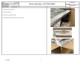
SAM BOOST™ SYSTEM
FULLY INSTALLED WITHOUT
ANTENNA & WATER TANK
LEVEL SENSOR

SAM BOOST™ WITH SMART NOZZLE N2P
QUICK START GUIDE
Refer to FSG-MNL-00232 for complete listing of Safety Hazards & Warnings
Sheet: FSG-MNL-00233
Revision 7 / 10 / 2023
Page: 1 of 7
Box #1 – SAM BOOST™ Electronic Components
A
B
A
A
C
D
E
F
G
H
I
A
B
H
I
F
F

SAM BOOST™ WITH SMART NOZZLE N2P
QUICK START GUIDE
Refer to FSG-MNL-00232 for complete listing of Safety Hazards & Warnings
Sheet: FSG-MNL-00233
Revision 7 / 10 / 2023
Page: 2 of 7
Box #2 – SAM BOOST™ Valves & Venting Components
c
c
a
a
b
d
e
c
c
d

SAM BOOST™ WITH SMART NOZZLE N2P
QUICK START GUIDE
Refer to FSG-MNL-00232 for complete listing of Safety Hazards & Warnings
Sheet: FSG-MNL-00233
Revision 7 / 10 / 2023
Page: 3 of 7
1. WHAT’S INCLUDED
1.1 Box #1 – SAM BOOST™ Electronic Components
A. Batteries & Battery Chargers
B. Wireless CAN Module & Antenna
C. Matrix Module
D. SAM BOOST™ System Harness
E. Cross Pump Backbone Harness with CAN Hubs
F. SAM BOOST™ Display, Display Labels, Power Module, & Adapter Plate
G. Alarm Buzzer (Optional)
H. Master Intake & Master Discharge Pressure Sensors
I. Caution Labels & Push-Pull Cover Placards
1.2 Box #2 – SAM BOOST™ Valves & Venting Components
a. 2” Preconnect Boost Valves, Pressure Sensors, & Valve Harnesses
b. Tank-to-Pump Boost Valve & Valve Harness
• Customer Specified, 3” or 4” Valve Size Available
c. Pump Venting Solenoid & Fittings
d. Water Tank Level Sensor & Fittings
e. Nozzle Color Handle Kit
2. PREPLAN INSTALLATION
□ Find optimal location for Antenna within 8’ of Wire to Wireless CAN Module
□ Lay out all components included in kit on pump as shown in System Layout
□ Verify harnesses are within reach of components
3. VALVE INSTALLATION
□ Remove Original Valve Components (Controls, drains, etc.)
□ Install Boost Valves
• May require rotating electric actuators for clearance. If valve is rotated then
position sensor calibration (password 08266) must be performed
□ Install Pressure Sensor into Drain Line or Gauge Line near Valve
□ Connect Harnesses to Valve Electric Actuator
• Point Electrical Connection Ports down or sideways to avoid water intrusion

SAM BOOST™ WITH SMART NOZZLE N2P
QUICK START GUIDE
Refer to FSG-MNL-00232 for complete listing of Safety Hazards & Warnings
Sheet: FSG-MNL-00233
Revision 7 / 10 / 2023
Page: 4 of 7
4. DISPLAY INSTALLATION
□ Remove Original Equipment Pressure Governor
□ Mount SAM BOOST™ Display with Adapter Plate
□ Replace Original Equipment Master Intake & Discharge Pressure Sensors
If Buzzer Included in Kit:
□ Remove Original Equipment Buzzer
□ Install SAM BOOST™ Display Buzzer
If Buzzer NOT Included in Kit:
□ Connect Buzzer into SAM BOOST™ Display
5. WATER TANK COMPONENT INSTALLATION
□ Install Pump Venting Solenoid to 1/4” NPT Port on Discharge Side of Pump
□ Install Check Valve Assembly to Water Tank or Discharge Side of Tank Fill Valve
□ Connect & Route 3/8” Push-On Hose Tubing between Solenoid & Check Valve
□ Locate & Remove OEM Water Tank Sensor
□ Install OEM Water Tank Sensor to SAM BOOST™ Tank Assembly
□ Install SAM BOOST™ Tank Assembly to Water Tank
6. ELECTRONIC MODULE INSTALLATION
□ Mount Matrix & Radio Modules to Valves
• Adapter fits 2.5”, 3”, or 4” Valves
7. HARNESS INSTALLATION
□ Connect all Harnesses shown on System Layout
□ Connect OEM Power & Ground to SAM BOOST™ Power & Ground
• Do NOT wire to circuit with heavy motor loads (such as primer, foam system)
• Wire to switched power source with 60 AMP protection on positive (+) side
8. WARNING LABEL & PLACARD INSTALLATION
□ Locate & Place Warning Labels where Preconnect Hoses are Deployed
□ Locate & Place Cover Placards over Original Valve Control Push Rods Panel Holes

SAM BOOST™ WITH SMART NOZZLE N2P
QUICK START GUIDE
Refer to FSG-MNL-00232 for complete listing of Safety Hazards & Warnings
Sheet: FSG-MNL-00233
Revision 7 / 10 / 2023
Page: 5 of 7
9. SOFTWARE QUICKSTART
□ Assign SAM BOOST™ Display UI Layout (Password: 14000)
□ Calibrate Water Tank Level Sensor (Password: 08265)
1. Fill Water Tank & Hit Button above Full icon
2. Empty Water Tank & Hit Button below the Empty icon
3. Hit Enter when complete to save
□ Verify Nozzle Names & Colors on Home Page
• If incorrect, change on password 00401 page
▪ Valve 1 is valve associated with top left icon of the screen
▪ Valve 2 is valve associated with top right icon of the screen

SAM BOOST™ WITH SMART NOZZLE N2P
QUICK START GUIDE
Refer to FSG-MNL-00232 for complete listing of Safety Hazards & Warnings
Sheet: FSG-MNL-00233
Revision 7 / 10 / 2023
Page: 6 of 7
□ Calibrate Nozzle Preset (Password: 10610)
Nozzle Preset Calibration will open discharge valve associated
with nozzle and automatically increase line pressure.
Calibration must be performed with two people
1. Engage Pump while inside Calibration Screen
2. Wake up Nozzle by Pressing 1 Button
3. Follow Instructions on Display
4. Press START 1 or START 2 to Calibrate Nozzle 1 or 2
5. Valve will open and line pressure will automatically increase until nozzle
meets desired pressure message
• Verify that Nozzle Bail is Fully Open when calibrating
6. The calibration process will automatically stop & close line when nozzle
pressure is reached

SAM BOOST™ WITH SMART NOZZLE N2P
QUICK START GUIDE
Refer to FSG-MNL-00232 for complete listing of Safety Hazards & Warnings
Sheet: FSG-MNL-00233
Revision 7 / 10 / 2023
Page: 7 of 7
10. FINAL COMMISSIONING CHECKLIST
INITIAL
PASS
CRITERIA
□
Verify Display shows SAM BOOST™ Splash screen while Pump in Road
Mode & Transmission in Drive Gear with Two People for Safety
□
Operate Preconnect Valves from Display - Full Open and Full Close
(Not required to be in Pump Gear)
□
Operate Tank-to-Pump Valve from Display - Full Open and Full Close
(Not required to be in Pump Gear)
□
Put into Pump Gear and verify no Warnings appear
□
Increase and Decrease Engine RPM with the Display
(If unable to do so, verify Governor Settings [Password: 00311])
□
Verify Emergency Idle functions with the Display
Press Mode button to revert to PSI Mode
□
While in PSI Mode, Increase Set Pressure to 100 PSI (or value that
increases Engine RPM.) Verify that Pump Set Pressure on Display
matches Master Discharge Gauge Pressure
□
Operate Nozzles to Open the Paired Preconnect Valves
□
With Two People for Safety, Validate Nozzle Calibration is correct by
having one person hold the bail Full Open & the other person at the
display checking Actual Pressure equals Rated Pressure with Full Hose
Length by pressing the Info Button on valve page
□
Validate Nozzle Signal Strength is reading appropriately. This can be
checked by pressing the info button on the valve page
□
Validate Truck voltage is reading appropriately. This can be checked by
pressing the info button on the valve page
(If incorrect, adjust on 06565 password page)
□
Drain tank while in Tank Mode and trip low tank warning audio & visual.
Warning should trip at ¼ tank level
(Validate buzzer operation and tank calibration)
□
Apply hydrant pressure, close tank-to-pump, and validate that nozzle
changes to a blue color
□
Check Engine Oil Pressure & Temperature
/