Alto ALTO SPS-28 User manual
- Category
- Vacuum cleaners
- Type
- User manual
This manual is also suitable for

AMERICAN-LINCOLN
TECHNOLOGY
Operator's
Manual
ENCORE R
SCRUBBER
Beginning with Serial No. 178575
READ THIS BOOK!
For new books, write to: Alto U.S., Inc.,1100 Haskins Road, Bowling Green, Ohio 43402.
This book has important information for the use and safe operation of this machine. Failure to read this book
prior to operating or attempting any service or maintenance procedure to your machine could result in injury
to you or to other personnel; damage to the machine or to other property could occur as well. You must have
training in the operation of this machine before using it. If you or your operator (s) cannot read English, have
this manual fully explained before attempting to operate this machine.
Si Ud. O sus operadores no pueden leer el Ingés, se hagen explicar este manual completamente antes de
tratar el manejo o servicio de esta máquina.
All directions given in this book are as seen from the operator's position at the rear of the machine.
Part No. 2-86-00207 Printed in the U.S.A
022800.
1998 American-Lincoln Technology®
U
L
®
ISO 9001
FILE A2287
#
E

AMERICAN LINCOLN TECHNOLOGY 1-2
ENCORE R Operator’s Manual
Chapter 1 (INSTRUCTIONS)
Specifications ....................................................................................................................................... 1-4
Safety Precautions ............................................................................................................................... 1-6
Machine Preparation ............................................................................................................................ 1-8
Machine Controls ................................................................................................................................. 1-9
Solution Control Knob ...................................................................................................................... 1-9
Battery Condition Meter .................................................................................................................... 1-9
Horn Button ...................................................................................................................................... 1-9
Light Switch (Option) ........................................................................................................................ 1-9
Squeegee Blade Switch ................................................................................................................... 1-10
High Recovery Light ......................................................................................................................... 1-10
Low Solution Light ............................................................................................................................ 1-10
Key Switch ....................................................................................................................................... 1-10
Scrub Brush Switch .......................................................................................................................... 1-11
ESP Option ...................................................................................................................................... 1-11
Hour Meter ....................................................................................................................................... 1-11
Pre Sweep Option ............................................................................................................................ 1-12
Brake ............................................................................................................................................... 1-12
Accelerator & Directional Control Pedal ........................................................................................... 1-13
Operating Instructions ......................................................................................................................... 1-14
Seat Adjustment ............................................................................................................................... 1-14
Pre-Start Checklist ........................................................................................................................... 1-14
Fill Solution Tank .............................................................................................................................. 1-14
To Start Machine .............................................................................................................................. 1-14
Post Start Checklist .......................................................................................................................... 1-14
To Transport Machine ...................................................................................................................... 1-14
To Begin The Cleaning Operation ................................................................................................... 1-15
To Stop The Cleaning Operation ...................................................................................................... 1-15
Post Operation Checklist .................................................................................................................. 1-16
To Drain Recovery Tank ................................................................................................................... 1-16
Helpful Hints For Cleaning................................................................................................................... 1-17
Service Chart ........................................................................................................................................ 1-18
Service Instructions ............................................................................................................................. 1-20
Scrub Deck-Splash Skirt/Side Squeegee Adjustment ...................................................................... 1-20
Replacing Scrub Brushes ................................................................................................................. 1-20
Replacing Pads On A Pad Driver ..................................................................................................... 1-20
Maintenance For The Rear Squeegee ............................................................................................. 1-20
Squeegee Wheel Adjustment ........................................................................................................... 1-21
Squeegee Blade Replacement ......................................................................................................... 1-21
Squeegee Angle Adjustment ............................................................................................................ 1-21
Parking Brake Adjustment................................................................................................................ 1-22
Setting The Reverse Delay Adjustment ............................................................................................ 1-22
Foot Pedal Neutral Adjustment ........................................................................................................ 1-22
Steering Adjustment-Pivot Adjustment ............................................................................................. 1-22
Steering Adjustment-Sprocket Adjustment ....................................................................................... 1-23
Solution Feed Hoses ........................................................................................................................ 1-23
Sweeper Option-Drive Belt Adjustments .......................................................................................... 1-24
Battery Removal ............................................................................................................................... 1-24
Battery Charging Instructions ........................................................................................................... 1-24
Trouble Shooting .................................................................................................................................. 1-26
TABLE OF CONTENTS

1-3 AMERICAN LINCOLN TECHNOLOGY
ENCORE R Operators’s Manual
Ordering Parts ...................................................................................................................................... 1-29
Hardware Abbreviations ...................................................................................................................... 1-30
Hardware Legend ................................................................................................................................. 1-31
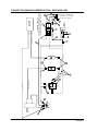
Machine Connection & Harness Routing ........................................................................................... 1-37
Connection Drawing............................................................................................................................. 1-39
Electrical Schematic ............................................................................................................................. 1-40
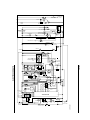
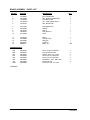
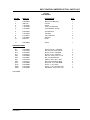
Chapter 2 (PARTS/ASSEMBLIES)
Table of Contents ................................................................................................................................. 2-1
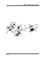
Frame Assembly .............................................................................................................................. 2-2
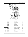
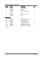
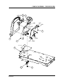
Front Wheel Drive ............................................................................................................................ 2-3
Rear Assembly ................................................................................................................................. 2-4
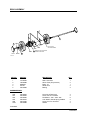
Steering ............................................................................................................................................ 2-5
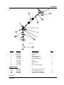
Brake ............................................................................................................................................... 2-6
Console ............................................................................................................................................ 2-8
Scrub Deck Actuator ........................................................................................................................ 2-10
Scrub Deck Assembly ...................................................................................................................... 2-12
Brushes & Pad Drivers ..................................................................................................................... 2-16
Squeegee Lift ................................................................................................................................... 2-18
Side Squeegee ................................................................................................................................. 2-20
Rear Squeegee (34” & 38”) .............................................................................................................. 2-24
Seat Assembly ................................................................................................................................. 2-26
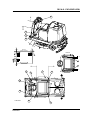
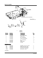
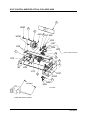
Vacuum Assembly ............................................................................................................................ 2-28
Forward/Reverse Pedal .................................................................................................................... 2-30
Recovery Tank ................................................................................................................................. 2-32
Solution Tank ................................................................................................................................... 2-33
Solution Control ................................................................................................................................ 2-34
Instrument Panel .............................................................................................................................. 2-36
Decals .............................................................................................................................................. 2-40
Chapter 3 (OPTIONS)
Table of Contents ................................................................................................................................. 3-1
Back-Up Alarm ................................................................................................................................. 3-2
Light Package .................................................................................................................................. 3-3
Overhead Guard .............................................................................................................................. 3-4
Strobe Light With Overhead Guard .................................................................................................. 3-5
Strobe Light Without Overhead Guard ............................................................................................. 3-7
Dual Vacuum System ....................................................................................................................... 3-9
Arm Rest Option .............................................................................................................................. 3-10
Main Broom Sweeper Option ........................................................................................................... 3-11
Broom Drive Sweeper ...................................................................................................................... 3-13
Fire Extinguisher .............................................................................................................................. 3-15
Seat Switch Kit ................................................................................................................................. 3-16
Frame & Flaps Option ...................................................................................................................... 3-17
ESP Recovery Option ...................................................................................................................... 3-19
Hopper Sweeper Option ................................................................................................................... 3-20
Dust Control Option .......................................................................................................................... 3-23
Spray Wand Option .......................................................................................................................... 3-25
Squeegee Wand Option ................................................................................................................... 3-27
Battery Options ................................................................................................................................ 3-28
Connection Drawing Sweeper Option............................................................................................... 3-31
Spare Parts Kits 34”, 38”, & CE Kit ................................................................................................... 3-33
Index .................................................................................................................................................. 3-34
Warranty ................................................................................................................................................ 3-37
TABLE OF CONTENTS

AMERICAN LINCOLN TECHNOLOGY 1-4
ENCORE R Operator’s Manual
SPECIFICATION FOR THE ENCORE R 34” AND 38”
POWER SUPPLY
Encore R (34”) 36 volt (3-12 volt batteries) 228 AH
Encore R (38”) 36 volt (6-6 volt batteries) 340 AH or 370 AH
CHARGER
Encore R (34” & 38”) 36 Volt output, 115V/60Hz or 230V/50Hz Input
MOTORS, VACUUM 1 HP. (.74 kw), 3 stage, tangential discharge
MOTORS, BRUSH 1.5 hp (1.11kw)
MOTOR, DRIVE 1.5 hp (1.11kw)
WHEELS (1) Front 12.0” (31.75 cm) (2) rear 12.0” (31.75 cm)
BRUSH SIZE
Encore R (34”) 2-17” (43.18 cm) DIA.
Encore R (38”) 2-19” (48.26 cm) DIA.
CLEANING PATH
Encore R (34 “) 34”(86.36 cm)
Encore R (38”) 38” (96.52 cm)
BRUSH SPEED 300 RPM
SOLUTION TANK 45 gallon (171 liter)
RECOVERY TANK 45 gallon (171 liter)
SPEED, TRANSPORT 5 MPH
SPEED, SCRUBBING 3.5 MPH
TURN RADIUS 56” (142.24 cm)
U-TURN AISLE WIDTH 80” (203.2 cm)
CLEANING RATE
Encore R (34”) 37000 sq. ft/hr (3426 sq. m/hr)
Encore R (38”) 42000 sq. ft/hr (3901 sq. m/hr)
GRADE CLEANING 3°
GRADE TRANSPORT 6°
LENGTH 71.5” (181.61 cm)
WIDTH
Encore R (34”) Machine 33.5” (85 cm)
Brush Housings 38.0” (96.52 cm)
Squeegee 42.0” (106.68cm)
SPECIFICATIONS

1-5 AMERICAN LINCOLN TECHNOLOGY
ENCORE R Operators’s Manual
Encore R (38”) Machine 33.5” (85 cm)
Brush Housings 41.0” (104.14 cm)
Squeegee 42.0” (106.68 cm)
HEIGHT 51” (129.54 cm)
HEIGHT W/OHG 80” (203.2 cm)
WEIGHT
Encore R (34”) 1800 lb. (817.25 kg)
Encore R (38”) 1820 lb. (826.33 kg)
WARRANTY
Machine 2 year
Polydur® tanks 8 years
Batteries 18 months, prorated
SPECIFICATIONS

AMERICAN LINCOLN TECHNOLOGY 1-6
ENCORE R Operator’s Manual
WARNINGS
THE FOLLOWING STATEMENTS ARE USED THROUGHOUT THIS MANUAL AS INDICATED IN THEIR DESCRIP-
TIONS
DANGER
To warn of immediate hazards which will result in severe personal injury or death.
WARNING
To warn of hazard or unsafe practices which could result in severe personal injury.
CAUTION
To warn of hazards or unsafe practices which could result in minor personal injury.
ATTENTION
To warn of unsafe practices which could result in extensive equipment damage.
NOTE
To give important information or to warn of unsafe practices which could result in equipment damage.
Read this manual carefully. The following information signals potentially dangerous
conditions to the operator or equipment. Know when these conditions can exist then,
take necessary steps to train machine operating personnel.
For the safe operation of this machine, read and understand all WARNINGS, CAUTIONS AND NOTES.
Water solutions or cleaning materials used with this type of machine can leave wet areas on the floor surface.
These areas can cause a dangerous condition for the operator or other persons. Always put CAUTION signs near the
area you are cleaning.
DO NOT put gasoline, combustible or flammable material in the solution or recovery tanks.
DO NOT operate the machine near flammable materials and vapors, it can ignite and cause an explosion. Do not
use with or near flammable materials such as: gasoline, grain dust, solvents and thinners. Only use a cleaning
concentrate recommended by the chemical manufacturer.
Improper use of heavy machinery can cause personal injury. Operate only when lids, doors, and access panels
are securely closed.
Use care when reversing machine in confined area.
Unplug the battery first to prevent possible injury when servicing a machine.
When working with the machine on its side, empty tanks, remove batteries, clear area of people and obstruc-
tions, and use additional people and proper procedures when lighting the machine.
Always empty the solution tank and recovery tank before doing maintenance.
You must have training in the operation of this machine before using it. READ THE OPERATORS MANUAL.
Do not operate this machine unless it is completely assembled.
Do not use this machine as a step or furniture.
Be careful when operating the machine on a ramp or incline. Do not operate machine on incline greater than 6°
or longer than 100’. Always move slowly on a ramp. Do not turn this machine on a ramp. Do not stop and leave this
machine on a ramp.
Always stop the machine on a level surface, put the power switch in the “O” position. Engage the parking brake.
To prevent injury, and damage to the machine, do not lift the machine or move it to an edge of a stair or loading
dock.
SAFETY PRECAUTIONS

1-7 AMERICAN LINCOLN TECHNOLOGY
ENCORE R Operators’s Manual
Lead acid batteries generate gases, which can cause an explosion. Keep sparks and flames away from
batteries. NO SMOKING. Charge batteries only in area with good ventilation.
Always wear eye protection and protective clothing when working near batteries. Remove all jewelry. Do not put
tools or other metal objects across the battery terminals, or the tops of batteries.
Maintenance and repairs must be done by authorized personnel only. Tighten all fasteners. Keep adjustments
according to the specifications given in the operator’s manual for the machine. Keep the electrical parts of the ma-
chine dry. For storage, keep the machine in a building.
Make sure that all labels, decals, warnings, cautions and instructions are fastened to the machine. Get new
labels and decals from American-Lincoln.
Your ENCORE R battery machine has been shipped complete, but do not attempt to operate without reading
the following instructions:
SAFETY PRECAUTIONS

AMERICAN LINCOLN TECHNOLOGY 1-8
ENCORE R Operator’s Manual
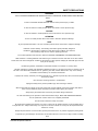
Your ENCORE R battery machine has been shipped complete, but do not attempt to operate without reading the
following instructions:
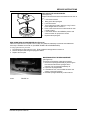
1. Uncrate machine
2. Install scrub brushes, as outlined in the Maintenance section of this manual.
3. Install batteries as follows
A. Turn the key to the “O” position
B. Lift the hinged seat and cover, then engage safety arm.
C. Use a battery lifting device with a 150 LB. (68KG) capacity to place the batteries in the battery
compartment.
D. Install Battery wires, as shown on page 1-23
E. Plug the polarized connector from the battery on into the 36 Volt plug provided.
F. Lower seat and cover assembly.
WARNING
Hydrogen gas is formed during the charging operation and is explosive. Only charge batteries in a well ventilated
area with the lid open. Avoid any smoking, open flame, or electrical sparks. Pulling out the charger plug, with the
timer on, will cause an arc and must be avoided.
MACHINE PREPARATION
C1836 FIGURE 1

1-9 AMERICAN LINCOLN TECHNOLOGY
ENCORE R Operators’s Manual
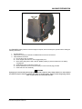
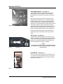
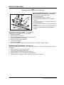
SOLUTION CONTROL KNOB - (See Figure 1)
The solution control knob is located to the left-hand side of
the steering wheel. Turning the knob clockwise will increase
the flow of solution and water. The farther the solution
control knob is turned the heavier the flow of water and
solution will be. Turning the knob counter clockwise will
decrease the flow of the solution and water. To turn the
water and solution off, turn the knob all the way counter-
clockwise.
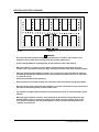
BATTERY CONDITION METER - (See Figure 2)
The meter shows the condition of the battery, while the
machine is running, under load. When battery voltage falls
below 31.5 volts for longer than 60 seconds, the low voltage
light will come on. Also the Brush/Water solenoids will be
locked out regardless of the previous conditions or com-
mands. This is a permanent lockout until power is turned off
to module. The low voltage lock out can be reset almost
immediately by turning off all power to the module for 3-5
seconds. Upon reapplying power, the lockout will be off and
will have to go through the 60 second delay before again
locking-out the Brush/Water solenoid. In a permanent low-
battery-voltage-condition, the machine can be functional
only for one-minute periods, and then only by repeating the
Ignition - “O” reset routine.
NOTE
Continual discharge of the battery below the “Red Zone” will
shorten battery life.
HORN BUTTON - (See Figure 3)
The horn button is located on the floor of the ENCORE R
operator’s compartment to the left of the pedals.
Light Switch (OPTION)
The light switch will activate any of the light options. The
switch is active at all times.
MACHINE CONTROLS
C1879 FIGURE 2
C1839 FIGURE 3
C1840 FIGURE 4

AMERICAN LINCOLN TECHNOLOGY 1-10
ENCORE R Operator’s Manual
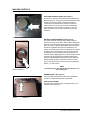
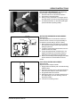
SQUEEGEE BLADE SWITCH (See Figure 4)
The squeegee blade switch is located on the console to
the left of the steering wheel. Pressing the squeegee
switch in the forward position turns the vacuum-motor off
and the squeegee blades are up. When the switch is in the
middle, the vacuum motor is on and the squeegee blade is
down. Pressing the squeegee switch in the downward
position, will raise the blade and keep the vacuum on.
HIGH RECOVERY LIGHT - (See Figure 5)
The High Recovery Warning Light is located on the
console. The recovery warning light will illuminate and
stay on approximately five minutes before the recovery
tank is full, giving ample time to complete the scrubbing
cycle before the mechanical float shuts off the vacuum to
the recovery tank.
LOW SOLUTION LIGHT - (See Figure 5)
The Low Solution Warning Light is located on the console.
The Solution Warning Light will illuminate when the solution
tank is empty, marking the end of the scrubbing cycle.
KEY SWITCH - (See Figure 6)
The Key Switch turned to the right, the “I” position, will
activate all machine systems. The optional lights can be
activated in the “O” position.
MACHINE CONTROLS
C1880 FIGURE 5
1
2
C1878 FIGURE 6
C1843 FIGURE 7

1-11 AMERICAN LINCOLN TECHNOLOGY
ENCORE R Operators’s Manual
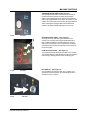
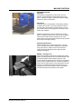
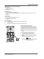
SCRUB BRUSH SWITCH - (See Figure 7)
The Scrub Brush Switch is located to the far left of the
steering wheel on the control panel. The Scrub Brush
indicator lights are located to the left of the Scrub Brush
switch.
With brushes up & the key switch is turned on the red
indicator will automatically be on. This indicates that the
scrub brushes are in the up position. Press and hold the
scrub brush switch down until the yellow indicator light
illuminates. This indicates that the scrub brushes are in the
normal scrub position. Press and hold the scrub brush
switch down until the green indicator light illuminates. This
indicates that the scrub brushes are in the heavy scrub
position. The lights will flash between the three positions.
To raise the scrub brushes press and hold forward the
Scrub Brush Switch until the red indicator light is illumi-
nated.
ESP OPTION - (See Figure 8)
The ESP Option transfers water from the recovery tank
through a filter and into the solution tank. When the switch
is in the “on” position the pump should operate when the
High Recovery light is illuminated. Clean the filter in the
recovery tank whenever the tank is emptied.
NOTE
Do not place clean water in the recovery tank when using
the ESP option, the solution tank could become overfilled
during operation.
HOUR METER - (See Figure 9)
The hour meter is activated when the key switch is in the
“on” position. The meter indicates the time, in Hours that
the machine has been operated. This is useful for deter-
mining service intervals.
MACHINE CONTROLS
1
`
2
3
C1837 FIGURE 8
C1845 FIGURE 9
C1847 FIGURE 10

AMERICAN LINCOLN TECHNOLOGY 1-12
ENCORE R Operator’s Manual
PRE SWEEP OPTION
Operation
The sweeper is designed to turn the broom on as it is
lowered. To lower the broom release hand lever on right
side. To remove the hopper, grasp each end of the hopper
and lift it up and out of the frame.
Adjustment
The main broom on this sweeper is free floating and has
no adjustment for wear. If your broom pattern is wide on
one side, place the broom in the down position, turn the
key off and loosen the mounting bolt on the left end of the
broom, then retighten.
Replace the main broom when it is either worn of dam-
aged. To replace the main broom: first remove the hopper.
Then remove the idler screw, through the hole in the
frame. Remove the idler bracket then pull the broom off the
drive and out the hopper opening.
Adjustment Side Broom
Adjust side flaps so they clear the ground by 1/16 of an
inch. As the side broom wears, adjustment is required to
keep proper broom pattern on the floor. Remove the
hopper and loosen the stop at lower right hand side,
reposition and tighten.
BRAKE - (See Figure 10)
Never leave operator’s seat without engaging the parking
brake. The parking brake is used on the rear wheels of the
mechanical system and is located on the floor of the
machine left of the directional control pedal. To set parking
brake, press foot pedal to set lock. To unlock the parking
brake, push the upper portion of the brake pedal. The foot
brake is not a method for slowing machine travel or for
stopping under normal conditions. This is accomplished
with the accelerator and directional control pedal.
MACHINE CONTROLS
FIGURE 11
C1848 FIGURE 12

1-13 AMERICAN LINCOLN TECHNOLOGY
ENCORE R Operators’s Manual
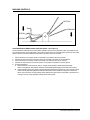
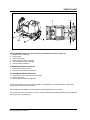
ACCELERATOR and DIRECTIONAL CONTROL PEDAL - (See Figure 11)
The Accelerator and Directional Control Pedal is located on the floor of the operator’s area. This pedal controls
the machine direction and travel speed. If the machine stops due to an electrical system overload in the power
panel controller, place the forward/reverse pedal in neutral to reset the controller.
1. Put foot pressure on the upper portion of the pedal. The machine will move forward.
2. Increase the foot pressure on the upper portion of the pedal to increase the forward speed.
3. Put foot pressure on the lower portion of the pedal. The machine will move in reverse.
4. Increase the foot pressure on the lower portion of the pedal to increase the reverse speed.
5. To stop the machine,
A. Allow directional control pedal to return to neutral (center position). Pedal will automatically
return to neutral when foot pedal is released. Neutral braking will engage to slow down the machine.
B. If neutral braking does not engage or disengages after slowing the machine to a crawl, reset the neutral
brake by briefly depressing the accelerator and directional control pedal according to the direction of
travel. If the machine is moving forward, briefly depress the upper portion of the pedal. If the machine is
moving in reverse, briefly depress the lower portion of the pedal.
MACHINE CONTROLS
NEUTRAL
NEUTRAL
REVERSE
FORWAR
D
P4066 FIGURE 13

AMERICAN LINCOLN TECHNOLOGY 1-14
ENCORE R Operator’s Manual
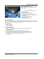
SEAT ADJUSTMENT- (See Figure 12)
This lever is located on front of the seat and allows the
seat to be adjusted.
Note
Before starting, perform the pre-start checks.
PRE-START CHECKLIST
1. Check controls for proper operation.
2. Make sure all controls are in the “O” position
3. Be sure accelerator/directional control pedal is in the
neutral position
4. Check all flaps for damage or wear
5. Check scrub brushes
6. Fill tank with water and detergent
TO FILL SOLUTION TANK
Remove the solution lid located on the back right side of the machine. Fill tank with 40 gallons of water and the
correct mixture of American Lincoln Commercial cleaner for the job on hand, first making sure that the solution
control knob is “OFF.” Place the lid back on the solution tank.
TO START MACHINE
1. Release parking brake
2. Turn key to “I” position
TO TRANSPORT MACHINE
1. Be sure the brushes and squeegee are in the “UP” or “RAISED” position with all other
controls in the “O” position.
2. Release parking brake.
3. Push forward on the directional control pedal to place the machine in motion.
4. Vary your foot pressure on the directional control pedal to obtain desired travel speed.
5. To stop, allow directional control pedal to return to neutral (centered) position. (Pedal will
automatically return to neutral when foot pressure is released).
6. Set parking brake.
C1851 FIGURE 14
OPERATING INSTRUCTIONS

1-15 AMERICAN LINCOLN TECHNOLOGY
ENCORE R Operators’s Manual
OPERATING INSTRUCTIONS
SOLUTION
TANK
RECOVERY
TANK
C1832 FIGURE 15
TO BEGIN THE CLEANING OPERATION
1. Lower brushes to the desired position.
SCRUB DECK = NORMAL RANGE OR HEAVY
2. Place the squeegee switch in the lower position.
SQUEEGEE BLADE = LOWER
3. Move solution control knob to the desired setting and begin operation.
SCRUBBING THE AVERAGE FLOOR WITH LIGHT TO MEDIUM SOILAGE
In this operation, cleaning is accomplished in one pass, with simultaneous solution feed, scrubbing and dirty
water pick up. The rate of solution feed and the speed of travel required will vary with floor condition. This
knowledge will come with operator experience.
TO STOP THE CLEANING OPERATION
Discontinue the cleaning operation whenever a solution tank is empty or a recovery tank is full. At this time,
discontinue the scrubbing cycle, put all controls in the forward position for transport and drive to the drain area.

AMERICAN LINCOLN TECHNOLOGY 1-16
ENCORE R Operator’s Manual
NOTE
After stopping, perform these post operation checks.
POST OPERATION CHECKLIST
Check Battery Condition and recharge, if necessary.
1. Check all flaps for wear, damage and adjustment.
2. Drain and clean recovery tank.
3. Clean recovery tank screen and float.
4. Check scrub brushes for wear or damage.
5. Check rear and side squeegee for wear, damage and adjustment.
TO DRAIN RECOVERY TANK
A drain hose for the recovery tank is located underneath the right side of the machine. To drain the tank,
remove and lower the hose and place in a suitable floor drain. Open Recovery Tank Lid and remove Drain
Plug to allow the soiled water to drain. When the draining operation is completed, Flush and Clean the recov-
ery tank, Install Drain Plug, close Recovery Tank Lid and replace the drain hose.
IMPORTANT
Always flush the recovery tank with clean water at the end of each cleaning cycle. Never let debris accumulate,
settle and harden in the tank or on associated hardware.
WARNING
Improper discharge of wastewater will damage the environment and is illegal. The U.S. Environmental Protection
Agency has established certain regulations regarding discharge of wastewater. Also, local city and state regula-
tions regarding wastewater discharge may be in effect in your area. Understand and follow the regulations in
your area. Be aware of the environmental hazards associated with the substances you dispose of.
NOTE
Replace disc brushes when bristles are reduced to 3/4 inch length. To order replacement brushes, see scrub
brush options in this manual. Replace squeegee rubbers when all usable edges have become rounded with wear,
impairing the wiping action. To order replacement squeegee rubbers, see the parts list in this manual.
OPERATING INSTRUCTIONS

1-17 AMERICAN LINCOLN TECHNOLOGY
ENCORE R Operators’s Manual
WARNING
- Do not turn the steering wheel sharply when the machine is in motion. The sweeper is very
responsive to movement of the steering wheel. Do not make sudden turns.
- Scrub in straight paths. Do not bump posts. Do not scrape the sides of the machine.
- When the machine is in motion, do not push the directional/speed control pedal all the way
forward. This is the same as starting in “high” and will put a strain on the motor and drive system.
- Plan your sweeping and scrubbing in advance. Try to arrange long runs with minimum stopping
and starting. Sweep debris from narrow aisles out into main aisle ahead of time. Do an entire floor,
or section at on time.
- Pick up oversize debris before sweeping.
- Allow a few inches of overlap of sweep and scrub paths. This will eliminate leaving dirty patches.
- Don’t turn steering wheel to sharply when machine is in motion. The machine is very responsive to
movement of the steering wheel; so avoid sudden turns.
- Try to follow as straight a path as possible. Avoid bumping into posts or scraping the sides of the
machine.
- When placing the machine in motion, avoid slamming the directional control pedal all the way
forward suddenly. This is equivalent to starting out in “HIGH” and puts needless strain on the
drive system. Periodically, turn the sweeping broom end for end to prevent the bristles from
“settling” in one direction.
HELPFUL HINTS FOR CLEANING
P4134 FIGURE 16

AMERICAN LINCOLN TECHNOLOGY 1-18
ENCORE R Operator’s Manual
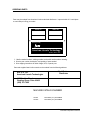
EVERY 8 HOURS or DAILY operation check and clean/adjust if necessary - (Figure 15):
1. All flaps for wear or damage
2. Parking brake
3. Clean recovery tank
4. Scrub brushes for wear or damage
5. Rear squeegee for wear or damage
6. Charge and check batteries
50 HOUR MAINTENANCE CHECKLIST:
7. Check battery electrolyte level
8. Lubricate front wheel bearing and pivot
100 HOUR MAINTENANCE CHECKLIST:
9. Lubricate drive chain, use motorcycle chain lube
10. Clean solution tank
11. Inspect chain sprockets and alignment
For service assistance, consult your local American-Lincoln Distributor, For best performance, replace worn
parts with genuine American-Lincoln parts.
Refer all Maintenance and Service Requirements to Qualified Maintenance Personnel.
Do not attempt to service this machine until you have read and understood all Safety Warnings associated with
the equipment you are working on.
SERVICE CHART
C1833 FIGURE 17

1-19 AMERICAN LINCOLN TECHNOLOGY
ENCORE R Operators’s Manual
WARNING
Maintenance and repairs must be done by authorized personnel only.
WARNING
Electrical repairs must be done by authorized personnel only. Consult your American-Lincoln Authorized Service
Person to do service procedures. Use only genuine American-Lincoln parts.
WARNING
Always park on a level surface, turn key off, and engage parking brake before working on the machine to keep it
from creeping or rolling.
IMPORTANT
If towing or pushing is required, disconnect motor lead located on the terminal block on the bottom of the
machine.
WARNING
Maintenance and repairs must be done by authorized personnel only. Always empty the solution tank and the
recovery tank before doing any maintenance. Keep all fasteners tight. Keep adjustments according to the
specifications as shown in the Service Manual for this machine.
WARNING
Always wear eye protection and protective clothing when working near batteries. Do not put tools or other metal
objects across the topes of the batteries.
WARNING
To prevent damage to the machine, and discharge across the tops of the batteries, do not fill the batteries above
the bottom of the tube in each cell. Wipe any acid from the machine or the tops of the batteries. Do not add acid
to a battery after installation.
WARNING
Always wear eye protection and protective clothing when working near batteries. NO SMOKING.
SERVICE CHART

AMERICAN LINCOLN TECHNOLOGY 1-20
ENCORE R Operator’s Manual
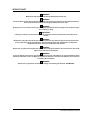
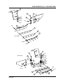
REPLACING THE SCRUB BRUSHES
(See Figure 18)
Replace Scrub Brushes when the bristles become worn to
¾”.
1. Lower scrub brushes.
2. Swing open side squeegees
3. Lift scrub brushes
4. The scrub brush is held in place by a ring. Pull the
brush straight down to remove it.
5. Push a new brush onto the scrub brush driver until
it clicks in place.
6. Lower Scrub Deck to the NORMAL position and
check the brush for proper floor contact.
7. Replace side squeegees.
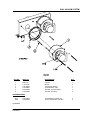
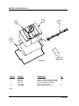
REPLACING PADS ON A PAD DRIVER-(See Figure 19)
Install a new pad when the old pad is worn or dirty. The pad driver assembly is removed and installed the
same way a standard scrub brush is. (See REPLACING THE SCRUB BRUSHES)
To change pad follow this procedure.
1. The pad driver is held in place by a ring. Pull the pad driver straight down to remove it.
3. Remove the pad holder using the spring wire retainer.
4. Replace the worn pad
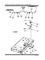
MAINTENANCE FOR THE REAR SQUEEGEE
(See Figure 20)
To remove the squeegee, follow this procedure:
1. Remove the squeegee assembly by loosening the
two knobs that attach the squeegee to the
machine. Pull the squeegee assembly off.
2. Inspect the squeegee blade.
3. If the blade is worn, turn the blade so that a new
edge is in the wiping position.
4. Reinstall squeegee assembly on the machine.
SERVICE INSTRUCTIONS
C1834 FIGURE 18
C1877 FIGURE 19
Page is loading ...
Page is loading ...
Page is loading ...
Page is loading ...
Page is loading ...
Page is loading ...
Page is loading ...
Page is loading ...
Page is loading ...
Page is loading ...
Page is loading ...
Page is loading ...
Page is loading ...
Page is loading ...
Page is loading ...
Page is loading ...
Page is loading ...
Page is loading ...
Page is loading ...
Page is loading ...
Page is loading ...
Page is loading ...
Page is loading ...
Page is loading ...
Page is loading ...
Page is loading ...
Page is loading ...
Page is loading ...
Page is loading ...
Page is loading ...
Page is loading ...
Page is loading ...
Page is loading ...
Page is loading ...
Page is loading ...
Page is loading ...
Page is loading ...
Page is loading ...
Page is loading ...
Page is loading ...
Page is loading ...
Page is loading ...
Page is loading ...
Page is loading ...
Page is loading ...
Page is loading ...
Page is loading ...
Page is loading ...
Page is loading ...
Page is loading ...
Page is loading ...
Page is loading ...
Page is loading ...
Page is loading ...
Page is loading ...
Page is loading ...
Page is loading ...
Page is loading ...
Page is loading ...
Page is loading ...
Page is loading ...
Page is loading ...
Page is loading ...
Page is loading ...
Page is loading ...
Page is loading ...
Page is loading ...
Page is loading ...
Page is loading ...
Page is loading ...
Page is loading ...
Page is loading ...
Page is loading ...
Page is loading ...
Page is loading ...
Page is loading ...
Page is loading ...
Page is loading ...
Page is loading ...
Page is loading ...
Page is loading ...
Page is loading ...
Page is loading ...
Page is loading ...
Page is loading ...
Page is loading ...
Page is loading ...
Page is loading ...
Page is loading ...
Page is loading ...
Page is loading ...
Page is loading ...
Page is loading ...
Page is loading ...
Page is loading ...
Page is loading ...
Page is loading ...
Page is loading ...
-
 1
1
-
 2
2
-
 3
3
-
 4
4
-
 5
5
-
 6
6
-
 7
7
-
 8
8
-
 9
9
-
 10
10
-
 11
11
-
 12
12
-
 13
13
-
 14
14
-
 15
15
-
 16
16
-
 17
17
-
 18
18
-
 19
19
-
 20
20
-
 21
21
-
 22
22
-
 23
23
-
 24
24
-
 25
25
-
 26
26
-
 27
27
-
 28
28
-
 29
29
-
 30
30
-
 31
31
-
 32
32
-
 33
33
-
 34
34
-
 35
35
-
 36
36
-
 37
37
-
 38
38
-
 39
39
-
 40
40
-
 41
41
-
 42
42
-
 43
43
-
 44
44
-
 45
45
-
 46
46
-
 47
47
-
 48
48
-
 49
49
-
 50
50
-
 51
51
-
 52
52
-
 53
53
-
 54
54
-
 55
55
-
 56
56
-
 57
57
-
 58
58
-
 59
59
-
 60
60
-
 61
61
-
 62
62
-
 63
63
-
 64
64
-
 65
65
-
 66
66
-
 67
67
-
 68
68
-
 69
69
-
 70
70
-
 71
71
-
 72
72
-
 73
73
-
 74
74
-
 75
75
-
 76
76
-
 77
77
-
 78
78
-
 79
79
-
 80
80
-
 81
81
-
 82
82
-
 83
83
-
 84
84
-
 85
85
-
 86
86
-
 87
87
-
 88
88
-
 89
89
-
 90
90
-
 91
91
-
 92
92
-
 93
93
-
 94
94
-
 95
95
-
 96
96
-
 97
97
-
 98
98
-
 99
99
-
 100
100
-
 101
101
-
 102
102
-
 103
103
-
 104
104
-
 105
105
-
 106
106
-
 107
107
-
 108
108
-
 109
109
-
 110
110
-
 111
111
-
 112
112
-
 113
113
-
 114
114
-
 115
115
-
 116
116
-
 117
117
-
 118
118


Alto ALTO SPS-28 User manual
- Category
- Vacuum cleaners
- Type
- User manual
- This manual is also suitable for
Ask a question and I''ll find the answer in the document
Finding information in a document is now easier with AI
Related papers
Other documents
-
Nilfisk-ALTO Vacuum Cleaner 692003 User manual
-
Diamond CROWN G17 User manual
-
-
Powr-Flite PAS26R Owner's manual
-
 Triple S Ace 20T User manual
-
BETCO E87032-00 StealthDRS24BT Owner's manual
-
Harper 5324224P1 Operating instructions
-
MasterCraft DM-900B Owner's manual
-
Windsor Saber Glide 28 Owner's manual
-
