Page is loading ...

PART NUMBER
SERIAL NUMBER
Installation and &
Servicing Instructions
Classic i Harmony 1
394.92B3 & 39662004
Classic i Harmony 3
394.96B7 & 39666005
Multifuel Boiler Stoves
IN1144 Edition A February 2011
This Manual Must Always be Available to the Stove Operator
This manual must be used in
conjunction with document
IN1173. The Wood and Mutlifuel
Chimney and Installation Guide.

© EUROHEAT DISTRIBUTORS (H.B.S) LTD. Feb 2011
E & OE Instructions Part number IN1144 Ed. A
2
IMPORTANT
Since April 2002 only Registered Competent Engineers may install solid fuel fired appliances without
involving the Local Authority Building Control Department. For more details contact HETAS. Euroheat
would suggest only Registered Competent Engineers install Euroheat appliances. If the installer is not a
registered Competent Engineer we would advise that property owners insurance company is contacted to
confirm their insurance is not affected.
The installation of this appliance must comply with all local regulations, including those referring to National
and European Standards, before it can be operated. The stove is not suitable for a shared flue. For England and
Wales only, the coming into force on 1st April 2002 of SI 2002 No 440 exempts the householder from this legal
requirement for the installation of solid fuel fired appliance whose rated heat output is 50kW or less in a building
having no more than 3 storeys (excluding any basement) if a Competent Engineer is employed who is registered
under the Registration Scheme for Companies and Engineers involved in the Installation and Maintenance of
Domestic Solid Fuel Fired Equipment operated by HETAS Ltd. These registered Competent Engineers may also carry
out associated building work necessary to ensure that the installed appliance complies with Building Regulations
without involving the Local Authority Building Control Department.
Improper adjustment, alteration, maintenance or the fitting of replacement parts not recommended by
the manufacturer can cause injury or property damage. Do not operate the stove with faulty seals or damaged
glass.
Due to the high operating temperatures of this appliance it should be located away from pedestrian traffic
and away from furniture and draperies. Do not store paper or wood near the appliance. Any mats and rugs put
in front of the stove should be fire proof and secured to prevent the possibility of tripping.
Advise all persons as to the stove’s high surface temperatures. If it is possible for children or infirm adults to
come into contact with the stove, fit a suitable fire guard.
It is imperative that all air passageways into, out of, and within the appliance are kept clean. All permanent
ventilation into the room provided for the stove must remain clear and unobstructed at all times. Consideration must
be given to the need for extra ventilation if another heating source needing air is to be operated simultaneously.
If an extraction fan is proposed to be fitted to a connecting area of the house, after the stove has been installed,
professional advice should be sought from a qualified engineer.
The user should be advised that the appliance should be inspected and the boiler air ways cleaned regularly
and the chimney cleaned at least annually. More frequent cleaning may be required and the advice of a qualified
chimney sweep should be sought.
Our range of stoves is capable of operating with outstanding efficiency if the flue system is correct. Because
so little heat is wasted to the flue it is possible that moisture within the products of combustion will condense if
the heat losses within the flue way are too great and allow the flue gasses to cool. For this reason we recommend
that the stove is fitted with a suitable flue liner, the same diameter as the flue spigot, to prevent the possibility
of acidic damage to the fabric of the chimney and damage to the stove which will reduce the longevity of the
stove.
When correctly installed, the stove is designed to produce heat, safely. It cannot do so if the installation is
less than absolutely stable, constructed of materials suitable for such an installation and consideration has not
been given to the possibility of people with less than ideal common sense operating it.
Have the existing chimney swept by a chimney sweep, although you will be lining the chimney, any deposits
left in the chimney will cause problems and may become a fire hazard.
Your attention is drawn to the precautions and responsibilities under the Health and Safety at Work Acts, and
whatever new legislation being introduced during the life of this document.

© EUROHEAT DISTRIBUTORS (H.B.S) LTD. Feb 2011
E & OE Instructions Part number IN1144 Ed. A
3
The Model Range Explained
Nestor Martin and Euroheat insist on progressive development to produce products which are market leading.
Our aims are to produce stoves with the latest innovations, user friendly operation and highly efficient for lower
cost operation.
This manual offers installation information for the range of Nestor Martin Harmony boiler stoves. In some cases
you find references in this document to the model size rather than the models exterior design. Although the
exterior clothes change between model sizes the internal workings are the same.
Model Identification
You will see on the front page of this document a label which confirms which model you have. This label also
advises you of the stoves unique serial number. This information is also attached to your stove for reference.
Important
Please ensure the warranty registration form is completed if you are the installer and confirm with the user that it
is their responsibility to return it to Euroheat. In this way the model and its history will be recorded for reference
in the future.
For the latest versions of manuals, technical information, accessories and spare parts visit the Euroheat web site.
Stoves supplied through Euroheat authorized retailers.
For England, Wales, Scotland and Northern Ireland
Euroheat Distributors (H.B.S). Ltd.
Unit 2, Court Farm Business Park,
Bishops Frome,
Worcestershire. WR6 5AY.
www.euroheat.co.uk
info@euroheat.co.uk
Whilst Euroheat are always happy to assist, please ensure you have read this manual and the chimney and
installation guide IN1173.
First contact your supplying retailer for assistance. If you find this not successful contact the Euroheat Technical
support team. Technical support telephone Number 01885 491117. E-mail tech@euroheat.co.uk.
Before telephoning ensure you have the stoves serial number to hand and that you are a Registered Competent
Engineer. If you are not a registered engineer seek one for assistance. A list of engineers can be obtained from
HETAS.
Euroheat unfortunately are NOT able to offer support for appliances which were not supplied by Euroheat.
Stoves supplied through Eireheat authorized retailers.
For Eire
Sean Murphy Heating Ltd
Kinvara
Co Galway
Eire
www.eireheat.com
sales@eireheat.com
(091)637701 Fax: (091)637797
International +353 91637701
For support for appliances supplied through Eireheat in Ireland please contact using the
details listed above.
Thermic Distribution Europe Sa
11 Rue De Lion
B-5660
Frasnes Les Couvin, Belgium.
www.nestormartin.com

© EUROHEAT DISTRIBUTORS (H.B.S) LTD. Feb 2011
E & OE Instructions Part number IN1144 Ed. A
4
*Free Air Requirement
Air requirement equivalent area. Building regulations Document J, advises that an air supply, permanently open
vents, should be installed for appliances:
If design air permeability >5.0m³/(h.m²) then 550mm²/kW of appliance rated output above 5kW
or
If design air permeability <5.0m³/(h.m²) then 550mm²/kW of appliance rated output
Equivalent air is as measured according to the method in BS EN13141-1:2004
It is unlikely that a dwelling constructed prior to 2008 will have an air permeability of <5.0m³/(h.m²) at 50pa
unless extensive measures have been taken to improve air-tightness.
_
Technical Data
Model
Harmony 1 3kW
Boiler
Harmony 1 6kW
Boiler
Harmony 3
7.5kW Boiler
Harmony 3
11kW Boiler
Fuel Type
Wood &
Smokeless Coal
Wood &
Smokeless Coal
Wood &
Smokeless Coal
Wood &
Smokeless Coal
Maximum Heat
Output to Room
7kW** 4kW** 8.5kW** 6kW**
Maximum Heat
Output to Boiler
3kW 6kW 7.5kW 11kW
Maximum Log
Length
457mm / 18” 432mm / 17” 558mm / 22” 482mm / 19”
Flue Outlet Size
(internal fitting)
125mm / 5” 125mm / 5” 153mm / 6” 153mm / 6”
*Free Air
Requirement
*2750mm² *2750mm² *6050mm² *6050mm²
Gross Efficiency 70% 70% 70% 70%
Water heating
capacity
Shipping Weight 162kg 180kg 206kg 220kg

© EUROHEAT DISTRIBUTORS (H.B.S) LTD. Feb 2011
E & OE Instructions Part number IN1144 Ed. A
5
Bends in flue pipe
Top exit
A flue pipe shall have no more than four bends, each providing a maximum change of direction of 45º, there
should be not more than two of these bends before an access point for sweeping and two between a sweeping
point and the flue terminal.
On top exit stoves, ideally the flue should rise vertically 1 meter before the first bend. It is permissible to have a
bend no greater than 45° from the top flue outlet, or off the top of a “T” piece, as long as it does not adversely
effect the flue draught.
Back exit
For a back outlet application using a “T” piece, this should be treated as two 45º bends. If a “T” piece is to be
used, the horizontal flue run from the back outlet of the stove shall only be used to connect the stove to a “T”
piece and shall not be more than 150mm in length.
Chimney and Flues
For information on flues see the Technical Guide IN1173 supplied with the stove.
Adequate access for sweeping must be provided.
It is not possible to sweep a flue through a Harmony multifuel boiler stove.
Carbon Monoxide Alarms
Where a new solid fuel stove is installed in a property a carbon monoxide alarm should be located in the same
room where the appliance is located:
a. on the ceiling at least 300mm from any wall or, if it is located on a wall, as high up as possible (above any
doors and windows) but not within 150mm of the ceiling; and
b. between 1m am 3m horizontally from the appliance.
Carbon monoxide alarms should comply with BS EN 50291:2001 and be powered by a battery designed to
operate for the working life of the alarm. The alarm should incorporate a warning device to alert users when the
working life of the alarm is due to end. Mains-powered BS EN 50291 Type A carbon monoxide alarms with fixed
wiring (not plug in types) may be used as alternative applications provided they are fitted with a sensor failure
warning device.

© EUROHEAT DISTRIBUTORS (H.B.S) LTD. Feb 2011
E & OE Instructions Part number IN1144 Ed. A
6
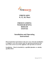
Position of Boiler Tappings
295
570
135
194
ID
120
120
390
265
125
65
230
Harmony 1 with 3kW Boiler
Harmony 1 with 6kW Boiler

© EUROHEAT DISTRIBUTORS (H.B.S) LTD. Feb 2011
E & OE Instructions Part number IN1144 Ed. A
7
189
644
74
291
ID
7.5kW
685
160
153
55
85
153 ID
275
7.5kW
75
300
410
570
BOILER
TAPPINGS
1” MALE
Harmony 3 with 11kW Boiler
Harmony 3 with 7.5kW Boiler

© EUROHEAT DISTRIBUTORS (H.B.S) LTD. Feb 2011
E & OE Instructions Part number IN1144 Ed. A
8
A
B
D
C
E
F
Minimum Installation Clearances
From Combustible Materials
In all installations surrounding flammable materials must not exceed 65°C.
Stove
Opening of stove
firebox
A
E
E
F
D
Non-combustible fireplace recess
In a fireplace recess
Free standing
From Non-combustible Materials.
Distance Required hearth surface
A
At least 300mm the edge of which should be clearly defined
B
At least 150mm the edge of which should be clearly defined
C
At least 150mm the edge of which should be clearly defined
D
At least 150mm the edge of which should be clearly defined
E
At least 150mm, if using side door 300mm
F
At least 50mm, however pipe work may require a greater distance
The clearances are given as guidance only and in all installations there should be enough space around the
stove for access for maintenance of the boiler and installation of the pipe work. The stove should be level on the
hearth
Stove
Opening of stove
firebox
A
B B
C
Minimum clearance
from flammable materials
A 300mm At least
B 250mm At least
C 300mm At least
D 300mm At least
E 250mm At least

© EUROHEAT DISTRIBUTORS (H.B.S) LTD. Feb 2011
E & OE Instructions Part number IN1144 Ed. A
9
Walls adjacent to free standing hearths
Walls that are not part of a fireplace recess or a prefabricated appliance chamber but are adjacent to hearths or
appliances also need to protect the building from catching fire.
(Note 1)
(Note 1)
at least
150mm
at least
150mm
X
X
T
Solid, non-combustible
material eg Masonary
or concrete
H
Location of hearth or appliance Solid, non-combustible material
Thickness (T) Height (H)
where the hearth abuts a wall and
the appliance is not more than
50mm from the wall
200mm
at least 300mm above the
appliance and 1.2m above the
hearth
where the hearth abuts a wall and
the appliance is more than 50mm
but not more than 300mm from the
wall
75mm
at least 300mm above the
appliance and 1.2m above the
hearth
where the hearth does not abut a
wall and is no more than 150mm
from the wall (see Note 1)
75mm
at least 1.2m above the
hearth
Note:1. There is no requirement for protection of the wall where X is more than 150mm

© EUROHEAT DISTRIBUTORS (H.B.S) LTD. Feb 2011
E & OE Instructions Part number IN1144 Ed. A
10
Hearths
The stove should stand wholly above a hearth constructed of suitably robust materials and should be able to
accommodate the weight of the appliance and its unsupported flue components. The materials should conform
to local Building Regulations and British Standards.
If the stove is not to stand in an appliance recess a hearth made of non-combustible board/sheet material or
tiles of at least 12mm thick may be used as long as the floor can accomodate the weight of the appliance and its
unsupported flue components.
The Harmony I and Harmony III multifuel stoves conform to standards DIN18891 and DIN 18891-A1 where the
hearth temperature does not exceed 100°C.
For further information on hearths visit our web site www.euroheat.co.uk
Changing Flue Outlet Harmony 1 with 3kW Boiler & Harmony 3 with
7.5kW Boiler
The Harmony 1 with 3kW boiler and Harmony 3 with 7.5kW boiler as supplied as the top flue option however it
is a very simple procedure to change to the rear flue outlet. Remove the top flue collar from the top of the stove
and the rear blanking plate from the rear of the stove. The flue collar can then be fitted to the rear of the stove,
the stainless steel protection tube must not be fitted when using the rear flue option. The blanking plate can be
fitted to the top of the stove ensuring that the stainless steel protection plate is fitted below the blanking plate.
Harmony I, 125mm ID
When using rear flue outlet fit top flue
protector plate before fitting cover plate.
This protection plate prevents damage
to the flue outlet blanking plate.
When using top flue outlet fit flue
outlet protection tube.
This protection tube prevents
damage to the flue outlet.

© EUROHEAT DISTRIBUTORS (H.B.S) LTD. Feb 2011
E & OE Instructions Part number IN1144 Ed. A
11
When using top flue outlet fit flue
outlet protection tube.
This protection tube prevents
damage to the flue outlet.
When using rear flue outlet fit top flue
protector plate before fitting cover plate.
This protection plate prevents damage
to the flue outlet blanking plate.
Harmony 3, 153mm ID
Changing Flue Outlet Harmony 1 with 6kW Boiler
To change to a top flue outlet an adapter is fitted to the rear outlet
of the stove, part No: 61771.
Remove the flue collar from the rear
of the stove and fit the inner part of
the adapter to the rear of the stove
using a gasket to seal the joint.
The outer section is then fitted to the
inner section with the four screws
supplied, again using the gasket
supplied to seal the joint.
The flue collar can then be fitted to
the top of the adapter.

© EUROHEAT DISTRIBUTORS (H.B.S) LTD. Feb 2011
E & OE Instructions Part number IN1144 Ed. A
12
Changing Flue Outlet Harmony 3 with 11kW Boiler
To change to a top flue outlet an adapter is fitted to the rear outlet of the stove, part No: 61772.
Remove the flue collar from the rear of the stove and fit the inner part of the adapter to the rear of the stove
using a gasket to seal the joint.
The outer section is then fitted to the inner section with the four screws supplied, again using the gasket supplied
to seal the joint.
The flue collar can then be fitted to the top of the adapter

© EUROHEAT DISTRIBUTORS (H.B.S) LTD. Feb 2011
E & OE Instructions Part number IN1144 Ed. A
13
Water Heating
Installation requirements in brief.
The installation for the appliance must be in accordance with the relevant requirements of the current Building
Regulations, current I.E.E. Wiring Regulations and the bylaws for the Local Water Authority. It should be in
accordance also with any relevant requirements of the Local Authority and the relevant recommendations of the
following current British Codes of Practice, or superseded amendments.
Water Circulation System.
Detailed recommendations for the water circulation are given in British Standards (for smallbore and microbore
central heating systems) or regulations relevant to country of installation.
Dependant upon the stove this can be installed to gravity primary with pumped central heating, fully pumped
with gravity by-pass.
This manual can only give some basic information as it is understood that our stoves are installed by
qualified and experienced installers only.
General Notes.
1. Gravity installations must provide an incline of horizontal pipes of at least 5mm/1000mm
2. Horizontal gravity inclined flow-pipes must be 1 inch (28mm). Reductions may be made in vertical pipes.
3. Radiators larger than 5ft are to be connected diagonally with respect to radiators and gravity systems i.e.
gravity heat leak radiators.
4. It is advisable to fit an adjustable circulating pump of which the rate of flow can be adapted to the actual
requirements. The pump can be fitted to the return or flow pipe depending on the system design. Fit an
isolation valve immediately before and after the pump so that it can be removed for repair purposes.
5. Cistern
A) overflow minimum 22mm.
B) system cold feed minimum 22mm copper and ensure it is the last connection on boiler common return.
C) minimum air gap 25mm overflow to end of vent.
D) minimum air gap 25mm overflow to water level (normal run).
6. Vent
A) minimum 22mm.
B) air separation devices should be fitted.
7. Slumber circuit. (Heat leak)
A) must cater with the minimum heat output.
B) no hand operated or automatic closing valves to be used.
8. Pump static head
A minimum 1.5 metres. i.e. height between cistern (cold feed tank) fall level and centre line of pump
position. This prevents cavitation occurring within the pump.
Hot Water Storage Vessel.
It is recommended that an indirect 190 litre (40 gallon) or larger hot water storage cylinder of the double feed
type complying with British Standards: or regulations relevant to country of installation. It should be lagged
and fixed vertically and as near as possible to the appliance, but with sufficient height to allow gravity flow. In
combined systems the water draw off pipes to the taps must be dead leg connection from the vent expansion
pipe.

© EUROHEAT DISTRIBUTORS (H.B.S) LTD. Feb 2011
E & OE Instructions Part number IN1144 Ed. A
14
Fitting of Electrical Controls.
Gravity system primary, pumped radiators.
A time clock control can be installed to activate the water circulating pump. This will also control the priority of
heat to either hot water or hot water and central heating.
A pipe thermostat should be fitted to the return pipe between the stove and central heating return gravity junction.
This must be so installed so that the pump cannot operate until the thermostat reaches the set temperature.
The system should operate with an 80°C flow 60°C return with average temperature of 70°C.
It is also recommended that a high limit pipe thermostat is fitted to the primary flow to override all other controls
to activate the circulating pump. We recommend that only fluid filled thermostats are used not by-metal.
Thermostat pre-wired kits are available, for configuration information ask your Euroheat
retailer for Euroheat instruction manual IN1027.
Basic Electrical Control Systems
Basic Electrical Control System (No time clock control)
With Room Thermostat
Electrical Supply.
All electrical wiring should be undertaken by a suitably qualified electrician. The method of connection to the
mains electricity supply should facilitate complete electrical isolation. Fused double-pole switch having a contact
separation of at least 3mm serving only the appliance may be used. The point of connection to the mains should
be readily accessible and adjacent to the appliance.
L
N
C
1
2
2
1
C
50°C
Low Limit
90°C
High Limit
230V
Pump
Pump
230V
L
N
Room
Thermostat
50°C
Low Limit
90°C
High Limit
C
2
1
2
C
1
N

© EUROHEAT DISTRIBUTORS (H.B.S) LTD. Feb 2011
E & OE Instructions Part number IN1144 Ed. A
15
3
4
7
2
6
5
1
1
90°C
50°C
Typical Installation Harmony 1 with 6kW Boiler, Harmony 3 with 7.5kW and 11kW Boiler
and heat leak radiator.
Suggested installation for stove heating domestic hot water
Heat leak Radiator
Header tank
Hot water cylinder
Cold water header tank
Pressure release valve
Typical Installation Harmony 1 with 3kW Boiler

© EUROHEAT DISTRIBUTORS (H.B.S) LTD. Feb 2011
E & OE Instructions Part number IN1144 Ed. A
16
Glossary of installation diagrams terms.
1. System Drain Points - The water circuit must have sufficient drain points to remove all water when required.
2. Water Circulating Pump - The circulating pump should be placed on the flow pipe from the appliance.
3. Heat Leak Radiator (slumber circuit) - All stoves which have water heating capability will produce heat to water
when running. This amount will vary depending on model and output setting. The heat leak should be sufficient
in size to absorb the water heating output with the stove in slow operation for long periods. It must never be
fitted with a thermostatic radiator valve.
4. Hot Water Cylinder - install a hot water cylinder which can supply the hot water demand of the property. It
is recommended that hot water cylinder capacity is at least 13 litres per kilowatt of water heating output. For
example 13 x 11 = 143 litres (37 gallons). However, if a heat leak is below the recommended output a traditional
cylinder with at least 40 gallons should be fitted.
5. Low Temperature Return Thermostat (FOR PUMPED HEATING)- Unless alternative mechanical or electrical options
are planned to be installed a low temperature return pipe thermostat must be installed. This thermostat should
be fitted on the last link to the stove between the joining of the hot water cylinder circuit and radiator return and
the stove return connection (as diagram). The pipe thermostat is to prevent large quantities of low temperature
water passing through the boiler for long periods. This can reduce flue temperatures and cause condensation.
NOTE: It is a requirement of the stoves warranty that at least a low temperature thermostat is fitted. Ideally a
HI-LO control should be fitted.
With gravity hot water and pumped radiator systems the pipe thermostat must control the water circulating
pump.
Several pre-wired control kits are available from Euroheat. For configuration information ask your Euroheat retailer
for Euroheat instruction manual IN1027.
6. High Temperature Pipe Thermostat - This thermostat is to prevent excess temperature in the water cylinder
circuit when the radiator circuit is not in operation. If excess temperature occurs, boiling of the primary circuit, this
thermostat should override all other controls and activate the circulation pump when required. This thermostat
should be adjusted between 85-88°C with installations of gravity hot water and pumped radiator circuits.
7. Radiator Circuit - this must be correctly matched to the heating output of the stove.

© EUROHEAT DISTRIBUTORS (H.B.S) LTD. Feb 2011
E & OE Instructions Part number IN1144 Ed. A
17
Removing Internal Baffles Harmony 1 with 3kW Boiler
Removing Top Baffles
Lift the right hand baffle upwards, lifting the rear
more than the front. Move the baffle towards the
stove back to allow the front edge to clear the
supporting ledge and pull forward. The left baffle
removes similarly. To replace the baffles reverse
the procedure, ensuring the front edges of the
baffles are pulled to the front of the stove and the
baffles are as close together as possible.
C
B
A
Removing Riddling Links
Remove or loosen rear heat shield
Remove screw “A”
Remove riddling link bar “B”
Remove Screws “C” and riddler guide seals.
Removing Grate
Lift Front of Grate remove through front door.
Removing Riddling Grate all Models

© EUROHEAT DISTRIBUTORS (H.B.S) LTD. Feb 2011
E & OE Instructions Part number IN1144 Ed. A
18
Access to the Boiler for Cleaning
Harmony 1 with 6kW Boiler & Harmony 3 with 11kW Boiler
For the stove to operate efficiently and safely the air ways
at the top and rear of the boiler need cleaning at regular
intervals, dependant upon the quality of the fuel being
burned.
We would recommend that after the first weeks use the
cast iron top plate is removed and the accumulation of
soots is monitored, then after two weeks it is inspected
again. This will allow you to gauge the frequency that the
boiler will need to be cleaned.
Only clean the airways when the stove is cold as any hot
embers could damage the vacuum cleaner being used.
The cast iron insert plate on the top of the stove needs to
be lifted out of the top plate to gain access to the boiler.
Once removed any ash can be vacuumed away.
Access to the rear of the boiler can be gained by removing
the steel blanking plate on the top of the boiler (see picture
opposite).
Adjusting thermostat setting Harmony 1 with 3kW Boiler & Harmony 3 with 7.5kW
The cold setting of the thermostat must be checked before
the stove is operated for the first time.
The thermostat can be adjusted in two places. (A) may be
bent for course adjustment and (B) for fine adjustment.
With the stove cold the gap between the inside left of the thermostat disc and the
cast iron body of the stove should be 1-2 mm at normal room temperature.
Note: the thermostat disc is designed to close at an angle.
A
B
1-2mm
Lift up the steel plate from the top of the boiler to
access the rear of the boiler for cleaning

© EUROHEAT DISTRIBUTORS (H.B.S) LTD. Feb 2011
E & OE Instructions Part number IN1144 Ed. A
19
You will need to use the cleaning brush supplied with your stove in conjunction
with a vacuum cleaner, we recommend the either the Motorised Ash Vac: Part
AC013, or the Standard Ash Vac: Part AC008.
Both available through your Euroheat dealer or directly from our web site www.
euroheat.co.uk
Motorised Ash Vac

© EUROHEAT DISTRIBUTORS (H.B.S) LTD. Feb 2011
E & OE Instructions Part number IN1144 Ed. A
20
Flue draught measured
with the air wash vent
fully open and all other
air supplies to the fire
closed.
Euroheat can supply
the flue measurement
gauges order number
MS026.
Note this is not a water
gauge used to measure
gas pressure.
0.04
0.02
0.06
millimetres
inches
Maximum
firing rate
Minimum
firing rate
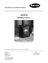
Draught requirements for multifuel stoves
Draught measured with the air wash vent fully open
and all other air supplies to the stove closed
.09
.08
.07
.06
.05
.04
.03
.02
.01
IN. OF WATER DRAFT OR PRESSURE - LOW RANGE
IN. OF WATER DRAFT OR PRESSURE - HIGH RANGE
.05
.1
.2
.3
.4
.5
.6
.7
.8
.9
1.0
The negative pressure created within the combustion chamber of the stove must be measured using a test hole
drilled into the flue, as close to the stove as possible and before any draught stabilizer that may be fitted to the
flue.
To ensure a constant air inlet size the readings should be taken with both the grate and the thermostatically
controlled air inlet to the stove shut, and the secondary air-wash inlet fully open.
A reading should be taken before the stove is lit to identify any possible problems which may be caused by air
being drawn down the flue by other heating appliances fitted with a flue, extraction fans, etc.. These should be
dealt with before lighting the stove.
Once lit, the stove and flue should be allowed to warm thoroughly before letting the fire burn at a low setting.
While taking the flue draught reading, all air entries to the combustion chamber of the stove should be closed
except the secondary air-wash shutter, which should be fully open. The draught measurement should read
approximately 0.5mm wg.
The stove should now be made to burn at its maximum output and another draught measurement taken, again
closing all air supplies to the stove other than the secondary air-wash shutter. The draught reading when the
burner is operating at its maximum setting should be approximately 1.5mm. wg.
A flue draught which is too low will result in the stove being difficult to light, responding only slowly to demands
for increased output and unable to reach its full heating output.
Flue draught which is too high will make control of the fire difficult, and makes it possible to over fire the stove,
which can seriously damage it. In this instance a flue draught stabaliser may need to be fitted.
The installation manual should be consulted if the flue draught pressure readings are incorrect.
/