
Manual for installation and operation
GB
Dynamic xs.plus / FU
Operator system for industrial doors

2 Manual for installation and operation, Dynamic xs.plus / FU GB (#89608)
2. Table of contents
1. Meaning of symbols . . . . . . . . . . . . . . . . . . . . . . . . .2
2. Table of contents . . . . . . . . . . . . . . . . . . . . . . . . . . . .2
3. General safety advice . . . . . . . . . . . . . . . . . . . . . . . .3
4. Product overview . . . . . . . . . . . . . . . . . . . . . . . . . . . .4
4.1 Dynamic xs.plus / FU supply package . . . . . . . . .4
4.2 Mounting options . . . . . . . . . . . . . . . . . . . . . . .7
4.3 Dimensions . . . . . . . . . . . . . . . . . . . . . . . . . . . .8
5. Preparation for mounting . . . . . . . . . . . . . . . . . . . . .9
5.1 General notes . . . . . . . . . . . . . . . . . . . . . . . . . .9
5.2 Checks . . . . . . . . . . . . . . . . . . . . . . . . . . . . . . . .9
5.3 Cabling layout . . . . . . . . . . . . . . . . . . . . . . . . .10
6. Installation . . . . . . . . . . . . . . . . . . . . . . . . . . . . . . . .11
6.1 Preparing the door . . . . . . . . . . . . . . . . . . . . .11
6.2 Mounting the shaft adapter . . . . . . . . . . . . . .11
6.3 Determine the mounting position of the
motor unit . . . . . . . . . . . . . . . . . . . . . . . . . . .12
6.4 Mounting the motor unit at the door . . . . . . .12
6.5 Mounting the torque support at the door . . . .13
6.6 Connect the emergency hand chain . . . . . . . .15
6.7 Secure the emergency operation facility . . . . .16
6.8 Setting the controlled quick release . . . . . . . . .16
6.9 Mounting the Control x.plus control unit . . . . .17
7. Initial operation . . . . . . . . . . . . . . . . . . . . . . . . . . . .18
7.1 Cabling for the operator system . . . . . . . . . . .18
7.2 Motor unit cabling . . . . . . . . . . . . . . . . . . . . . .18
7.3 Cabling for the Control x.plus control unit . . . .22
7.4 Connecting the power supply . . . . . . . . . . . . .26
7.5 Overview of the Control x.plus control unit . . .32
7.6 Express programming . . . . . . . . . . . . . . . . . . .32
7.7 Changing the rotational direction . . . . . . . . . .35
7.8 Check the system . . . . . . . . . . . . . . . . . . . . . .36
8. Operation . . . . . . . . . . . . . . . . . . . . . . . . . . . . . . . . .37
8.1 Standard operation . . . . . . . . . . . . . . . . . . . . .37
8.2 Emergency operation . . . . . . . . . . . . . . . . . . . .38
8.3 Maintenance release . . . . . . . . . . . . . . . . . . . .40
9. Extended operator functions . . . . . . . . . . . . . . . . .41
9.1 General notes on extended
operator functions . . . . . . . . . . . . . . . . . . . . . .41
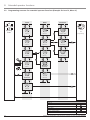
9.2 Programming structure for extended operator
functions (Example for Level 2, Menu 2) . . . . .42
9.3 General overview of the programmable
functions . . . . . . . . . . . . . . . . . . . . . . . . . . . .43
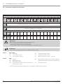
9.4 Functions overview for the levels . . . . . . . . . . .44
10. Messages . . . . . . . . . . . . . . . . . . . . . . . . . . . . . . . . .54
10.1 Overview of the display functions . . . . . . . . . .54
10.2 Status messages . . . . . . . . . . . . . . . . . . . . . . .54
10.3 Fault messages . . . . . . . . . . . . . . . . . . . . . . . .55
10.4 Flow chart showing fault messages for control
units with keypad on cover and key switch . . .56
10.5 Rectifying faults . . . . . . . . . . . . . . . . . . . . . . . .57
11. Attachment . . . . . . . . . . . . . . . . . . . . . . . . . . . . . . . .59
11.1 Technical data . . . . . . . . . . . . . . . . . . . . . . . . .59
11.2 EC Declaration of Conformity . . . . . . . . . . . . .61
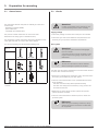
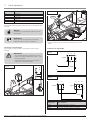
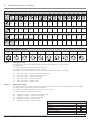
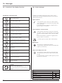
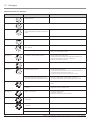
1. Meaning of symbols
Caution!
Danger of personal injury!
The following safety advice must be observed
at all times so as to avoid personal injury!
Attention!
Danger of material damage!
The following safety advice must be observed
at all times so as to avoid material damage!
Advice / Tip
Check
Reference
i
Advice
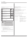
Type plate on Dynamic xs.plus / FU motor unit
Type: ____________________________________________________
Art. No.: _________________________________________________
Product No.: ______________________________________________
Safety devices
“Door OPEN” position
Intermediate position
“Door CLOSED” position
Maintenance indicator
Messages specific to the operator system
Impulse
(remote control, external control elements)
Operation
Controls and motor unit symbols
Type plate on Control x.plus control unit
Type: ____________________________________________________
Art. No.: _________________________________________________
Product No.: ______________________________________________

Manual for installation and operation, Dynamic xs.plus / FU GB (#89608) 3
Information on installing the operator system
• Ensure that the door is in good mechanical condition.
• Ensure that the door is balanced.
• Ensure that the door opens and closes properly.
• Ensure that there is a suitable mains connection near the door.
• Remove all unnecessary components from the door (e.g. cables, chains,
brackets).
• Render any installations inoperable that will no longer be needed after
the operator system has been installed.
• Before commencing cabling works, you MUST disconnect the operator
system from the mains supply.
Adhere to the safety period of 10 seconds to guarantee that the
operator system is voltage free.
• Adhere to the local protection regulations.
• The electricity supply cables and control cables MUST be laid separately.
• Install the operator system with the door in the CLOSED position.
• Install all the impulse transmitters and control devices (e.g. remote
control buttons) within sight of the door and at a safe distance from
the moving parts of the door. A minimum installation height of 1.5 m
must be observed.
• Permanently fix the warning signs, which advise of the danger of
becoming trapped, at conspicuous locations (if applicable).
• Ensure that no part of the door extends across public footways or roads
when the installation is complete.
Information on commissioning the operator system
After initial operation, the persons responsible for operating the door
system, or their representatives must be familiarised with the use of the
system.
• Make sure that children cannot access the door control unit.
• Before moving the door, make sure that there are neither persons nor
objects in the operating range of the door.
• Test all existing emergency command devices.
• Never insert your hands into a running door or moving parts.
• Pay attention to any parts of the door system that could cause crushing
or shearing damage or accidents.
The EN 13241-1 regulations must be observed.
Information on servicing the operator system
To ensure proper operation, the following items must be checked regularly
and repaired if necessary. Before any works to the door system are under-
taken, the operator system must be disconnected from the mains.
• Check all movable parts of the door and operator system.
• Check the door system for signs of wear or damage.
• Check whether the door can be easily moved by hand.
Information on cleaning the operator system
Never use water jets, high pressure cleaners, acids or bases for cleaning.
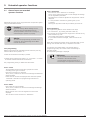
Please read carefully!
IMPORTANT SAFETY INSTRUCTIONS:
IMPORTANT - PLEASE OBSERVE ALL SAFETY INSTRUCTIONS TO PREVENT INJURY TO
PERSONS.
PLEASE KEEP THESE INSTRUCTIONS FOR FURTHER USE.
IMPORTANT INSTRUCTIONS FOR SAFE INSTALLATION:
IMPORTANT - INCORRECT INSTALLATION CAN RESULT IN SERIOUS INJURY.
PLEASE FOLLOW ALL INSTALLATION INSTRUCTIONS.
Target group
This operator system may only be installed, connected and put into
operation by qualified and trained professionals!
Qualified and trained specialist personnel are persons
- who have knowledge of the general and special safety regulations,
- who have knowledge of the relevant electro-technical regulations,
- with training in the use and maintenance of suitable safety equipment,
- who are sufficiently trained and supervised by qualified electricians,
- who are able to recognise the particular hazards involved when working
with electricity,
- with knowledge regarding applications of the EN 12635 standard (instal-
lation and usage requirements).
Warranty
For an operations and safety warranty, the advice in this instruction man-
ual has to be observed. Disregarding these warnings may lead to personal
injury or material damage. If this advice is disregarded, the manufacturer
will not be liable for damages that might occur.
Batteries, fuses and bulbs are excluded from warranty.
To avoid installation errors and damage to the door and operator system,
it is imperative that the installation instructions are followed. The system
may only be used after thoroughly reading the respective mounting and
installation instructions.
The installation and operating instructions are to be given to the door
system user, who must keep them safe.
They contain important advice for operation, checks and maintenance.
This item is produced according to the directives and standards
mentioned in the Manufacturer's Declaration and in the Declaration of
Conformity. The product has left the factory in perfect condition with
regard to safety.
Power-operated windows, doors and gates must be checked by an expert
(and this must be documented) before they are put into operation and
thereafter as required, but at least once a year.
Correct use
The operator system is intended exclusively for opening and closing
industrial doors.
The maximum torque must be observed.
Door requirements
The operator system is suitable for use with spring balanced sectional
doors.
Beside the advice in these instructions, please observe the general
safety and accident prevention regulations!
Our sales and supply terms and conditions are effective.
3. General safety advice

4 Manual for installation and operation, Dynamic xs.plus / FU GB (#89608)
Version with controlled quick release (SEG)
3 Chain connecting link (2x)
4 Wing-nut
5 Washer (2x)
6 Nut, width across flats: 13
7 Securing bolt
8 Mounting bracket
9 Release cable (6,000 mm)
10 Dynamic xs.plus motor unit, SEG
-y
9
-y
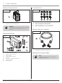
4.1 Dynamic xs.plus / FU supply package
4. Product overview
4.1 / 2
Version with chain and maintenance release (KE/WE)
1 Dynamic xs.plus motor unit, KE/WE
2 Release cable (200 mm)
3 Chain connecting link (2x)
4 Wing-nut
5 Washer (2x)
6 Nut, width across flats: 13
7 Securing bolt
8 Mounting bracket
4.1 / 1
The Dynamic xs.plus / FU motor unit can be supplied in the
following versions as required:
3
4
5
6
7
8
1
2
10
3
4
5
6
7
8
-
9 Release cable (6,000 mm)
11 Dynamic xs.plus motor unit, SE
Quick release version (SE)
9
4.1 / 3
11

Manual for installation and operation, Dynamic xs.plus / FU GB (#89608) 5
12 Dynamic xs.plus / FU motor unit
-y
Frequency converter (FU) version
4.1 / 4
12
Advice:
The frequency converter (FU) version is available
with release types KE/WE/SEG and SE (4.1 / 1 -
4.1 / 3).
4. Product overview
20
4.1 / 5
13 Control x.plus control unit
14 Wood screw 4 x 35 (4x)
15 Wall plug (4x)
16 Plastic screw 4 x 10 (4x)
17 Key (2x)
18 Foot for control unit housing (4x)
19 Operating handle
20 Shorting plug
Control x.plus control unit
13
18
16
17
14
15
19
4.1 / 6
Screw connection set
21 M16 screw fixing for 4-pole flat cable
22 M20 screw fixing for 6-pole flat cable
23 M16 screw fixing for 4 - 6 mm round cable
24 M20 screw fixing for 6 - 9 mm round cable
21 22 23 24
Mounting parts for push-on assembly
4.1 / 7
25 Cable loom, motor unit - control unit
Cable loom, motor unit - control unit
25
Tip:
Additional mounting parts are required for
fixing the motor unit.

6 Manual for installation and operation, Dynamic xs.plus / FU GB (#89608)
4.1 / 9
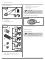
31 Feather key 1 (1x)
(only for adapters without integrated feather key)
32 Feather key 2 (3x)
(only for adapters without integrated feather key)
Reference:
The relevant instructions are to be followed if
the motor unit is to be installed according to
other mounting options.
i
25,4
6,35
27,55
25,4
6,4
17,8
31,75
SW 32,1
6,35
29,4
31
34
35
Shaft adapter set
25,4
6,4
19,0
32
33
4.1 / 8
26 Screw B4.8 x 13 (4x)
27 Torque support
28 Fixing bracket (2x)
29 Nut with shoulder SW 13 (6x)
30 Screw M8 x 16 (6x)
Steel sheet torque support
26
27
28
29
30
4. Product overview
33 Feather key 3 (3x)
(only for adapters without integrated feather key)
34 Shaft adapter (1x)
(Dimensions according to requirements)
35 Adjusting ring (2x)
4.1 / 10
36 Emergency hand chain (optional)
Emergency hand chain extension (optional)
36
Safety devices (optional)
Remote control (optional)
Reference:
To ascertain the exact contents of the supply
packages for optional accessories, please refer to
the relevant instructions included.
i

Manual for installation and operation, Dynamic xs.plus / FU GB (#89608) 7
4. Product overview
4.2 Mounting options
-
Push-on assembly
Assembly with spindle chain drive (optional)
-y
-y
Assembly with chain drive (optional)
-y
-y
4.2 / 1
4.2 / 3
4.2 / 2
Assembly with push-on shaft adapter (optional)
4.2 / 4

-y
4.3 / 4
≥ 125
≥ 600
≥ 110
≥ 68.
Space required when installed vertically
(Recommended for motor unit with emergency hand chain)
Space required for Control x.plus control unit
4.3 / 5
240
150
300
60*
220
* Opening side
4. Product overview
4.3 Dimensions
Dynamic xs.plus with emergency hand crank
4.3 / 1
68.
294
428
388
69.
104
Dynamic xs.plus / FU
4.3 / 2
68.
294
302
428
388
69.
104
Control x.plus control unit
4.3 / 3
240
146.
77
8 Manual for installation and operation, Dynamic xs.plus / FU GB (#89608)

Manual for installation and operation, Dynamic xs.plus / FU GB (#89608) 9
5.1 General notes
The instructions describe the push-on assembly for motor unit
versions with:
- Maintenance release (SE/WE)
- Quick release (SE)
- Controlled quick release (SEG)
The pictures in these instructions are not true-to-scale.
Dimensions are always given in millimetres (mm)!
The illustrations in these instructions show the installation on the
inner right hand side, for a door with normal fittings.
For correct mounting you will need the following tools:
* Grease
5.1 / 1
8 / 13 2 / 2,5 2,5
3 / 4 / 5 ø 9
* ø 4 - 20
Attention!
The operator system cannot be disengaged
from the outside.
A separate entrance must be available in order
to gain access to the garage in the event of a
malfunction.
The door must be properly installed and must have been checked
to ensure that it functions correctly.
• Ensure that a suitable mains connection and a mains disconnec-
tion facility are available for your door system.
• Check to ensure that the door to be operated fulfils the follo-
wing conditions:
- The door must move easily when operated manually.
- The door must always remain stationary in any position wit-
hout external restraint.
• Determine on which side of the door system the operator
system should be mounted.
• Check to ensure that there is sufficient space to mount the
operator system.
Door system
Reference:
The relevant instructions must be observed
when mounting the operator at the door.
i
Reference:
When using and installing accessories, always
observe the specific instructions included with
the equipment.
i
5.2 Checks
Attention!
In order to guarantee correct mounting, carry
out the following checks before installing.
Supply package
• Check the package to ensure that all the parts are included.
• Check that you have all the additional components that are
necessary for your particular installation requirements.
5. Preparation for mounting

5. Preparation for mounting
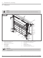
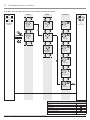
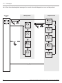
Advice:
This is just an example of a cabling layout; the layout can vary according to the type of door and the associated
equipment.
Reference:
The relevant installation instructions must be observed when mounting and connecting door sensors, control elements
and signalling devices.
i
5.3 / 1
G
I
J
J
G
H
I
K
D
B
L
E
A Dynamic xs.plus / FU motor unit
B Control x.plus control unit
C Signalling device (e.g. signal light)
D Mains connection
Useable length:
- 0.8 m (400 V)
- 1.1 m (230 V)
E Mains isolator switch
F Spring safety device, supplied by customer
G Door sensors for cable slack device
H Optosensors
I Photocell barrier
J Housing, connection unit
K Door sensor for wicket door
L Cable loom, motor unit - control unit
C
A
F
5.3 Cabling layout
H
10 Manual for installation and operation, Dynamic xs.plus / FU GB (#89608)

Manual for installation and operation, Dynamic xs.plus / FU GB (#89608) 11
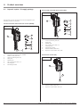
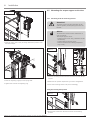
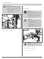
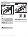
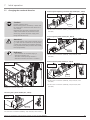
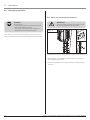
• Deburr the spring shaft (B) using a file.
• Push the adapting ring (A) onto the spring shaft (B).
• Tighten the screw of the adjusting ring (A).
• Grease the spring shaft.
• Push the shaft adapter (C) onto the spring shaft (B).
Only for shaft adapters without integrated feather keys:
• Insert the feather key into the shaft adapter.
A
B
Attention!
To ensure proper operation,
- there must be a 3 mm gap between the
frame and the adjusting ring,
- the shaft adapter must fit on the spring shaft
with as little play as possible in the direction
of rotation.
~ 3
6.2 / 1
C
6.2 Mounting the shaft adapter
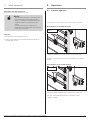
• Secure the door.
Caution!
- To prevent falls, the installation works must be
carried out from a safe standing position.
A lifting platform or scaffold can be used.
- To avoid injury, the door must be secured for
the duration of the installation works to
prevent it from being opened or closed.
6.1 / 1
6.1 Preparing the door
6. Installation

-y
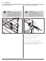
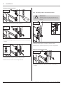
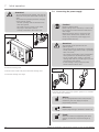
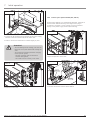
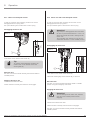
6.4 Mounting the motor unit at the door
6.4 / 2
• Push the torque support (A) at the previously determined positi-
on onto the gudgeons of the motor unit.
• Screw the torque support (A) to the motor unit.
A
Attention!
To ensure proper operation, all the gudgeons
on the motor unit must engage in the pattern
of holes in the torque support.
B 4,8 x 13
-y
• Remove the motor unit and the torque support from the door.
6.4 / 1
-y
• Determine the mounting position of the torque support and the
motor unit.
6.3 / 1
B
A
Tip:
The position can be determined by holding the
torque support and the motor unit at the door.
Attention!
To ensure proper operation, the following
conditions must apply:
- All motor unit gudgeons (C) engage in the
torque support (A).
- The motor unit’s emergency hand chain (D)
can be operated without any restriction.
The mounting position of the motor unit on the torque
support (A) varies for different doors.
The screw position (B) for the force absorption of the torque
support (A) can be located on the frame or on another fixed
building component (e.g. wall).
D
C
6. Installation
6.3 Determine the mounting position of the
motor unit
12 Manual for installation and operation, Dynamic xs.plus / FU GB (#89608)

6. Installation
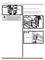
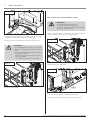
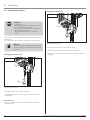
-y
• Place the motor unit at the previously determined position onto
the shaft adapter.
6.4 / 3
-y
6.4 / 4
B
• Place the adjusting ring (B) on the spring shaft.
• Tighten the screw of the adjusting ring.
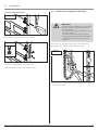
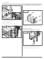
6.5 Mounting the torque support at the door
6.5.1 / 1
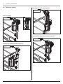
Advice:
The illustration of the bracket combination is
only an example.
The torque support can be
- screwed to the frame using a different bracket
combination,
- screwed directly onto the frame,
- fixed to another static building component
(e.g. a wall).
• Hold the mounting bracket between the frame and the torque
support.
• Determine the position required for your door configuration.
• Screw the mounting bracket into place accordingly.
Attention!
To ensure proper long-term operation of the
operator system, the torque support must not
be bent.
6.5.1 Mounting with the mounting bracket
Manual for installation and operation, Dynamic xs.plus / FU GB (#89608) 13
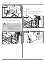
6.5.1 / 2
• Remove the screws from the door frame at the mounting
position.
Using the existing hole pattern

6.5.2 / 1
• Hold the torque support in place on the door frame.
• Determine the position required for your door configuration.
Attention!
To ensure proper long-term operation of the
operator system, the torque support must not
be bent.
6.5.2 Mounting without the mounting bracket
6.5.2 / 2
• Remove the screws from the door frame at the mounting
position.
Using the existing hole pattern
6.5.1 / 5
• Screw the torque support to the mounting bracket.
• Release the door so that it is no longer secured.
M8 x 16
• Screw the mounting bracket to the door frame at the mounting
position.
6.5.1 / 4
6. Installation
6.5.1 / 3
Creating a new hole pattern
• Drill holes in the frame at the screw positions.
14 Manual for installation and operation, Dynamic xs.plus / FU GB (#89608)

6. Installation
6.5.2 / 3
Creating a new hole pattern
• Drill holes in the frame at the screw positions.
6.5.2 / 4
• Screw the torque support to the door frame.
• Release the door so that it is no longer secured.
M8 x 16
Manual for installation and operation, Dynamic xs.plus / FU GB (#89608) 15
6.6 / 1
The motor unit’s emergency hand chain can be extended in
length using an optionally available extension chain.
• Join the ends of the emergency hand chain together with the
chain connecting link.
Attention!
To ensure that the emergency operation facility
functions properly, the following conditions
must be ensured:
- The ends of the emergency hand chain must
be joined together.
- The edges of the connecting link must be
exactly aligned with each other when closed.
- The emergency hand chain should not be
twisted.
6.6 Connect the emergency hand chain

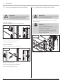
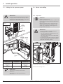
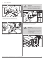
6.8 Setting the controlled quick release
Attention!
To prevent damage to the motor unit, the door
must be in the CLOSED position.
-y
6.8 / 1
• Open the operator control unit.
Caution!
Danger of electric shock:
Before cabling works commence,
a check must be carried out to ensure that the
cables are at zero voltage.
Measures must be taken to ensure that the
cables remain dead for the duration of the
works (e.g. prevent the power supply from
being switched back on).
• Drive the door to the CLOSED position using the emergency
operation facility.
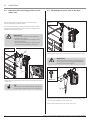
6.7 / 1
Installation example 1
Secure the emergency hand chain at the door frame.
• Fix the securing assembly to the frame.
• Secure the emergency hand chain.
Attention!
The emergency hand chain must be secured to
prevent it from being caught in the door
mechanism when the door is operated.
Installation example 2
Secure the emergency hand chain on the wall.
6.7 / 2
• Fix the bracket to the wall.
• Fix the securing assembly to the bracket.
• Secure the emergency hand chain.
6.7 Secure the emergency operation facility
6. Installation
16 Manual for installation and operation, Dynamic xs.plus / FU GB (#89608)

6. Installation
6.8 / 2
• Press down the cam (A) until the ratchet brace (B) disappears
completely into the positioning box.
• Hold the cam (A) pressed.
• Fix the cam (A) in position with the screw (C).
A
B
-y
6.8 / 3
• Close the control unit.
B
C
Manual for installation and operation, Dynamic xs.plus / FU GB (#89608) 17
6.9 / 1
• Mount the Control x.plus control unit on the same side as the
motor unit.
6.9 Mounting the Control x.plus control unit
6.9 / 2
• Using a step drill, open up the corresponding cable inlet.
• Close the inlet using the corresponding screw fitting.
Creating further cable inlets
It is only necessary to create further cable inlets if additional
systems are to be connected to the control unit.

18 Manual for installation and operation, Dynamic xs.plus / FU GB (#89608)
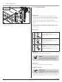
7.2 Motor unit cabling
• Loosen the screws on the housing cover.
• Remove the housing cover.
7.2 / 1
7.2.1 Preparation
Attention!
- To avoid damage, it is essential that the
following points be observed:
- The local protection regulations are to be
complied with at all times.
- - The mains cables and control cables MUST
be laid separately.
- To maintain the specified protection category
of the operating system, the cables must be
fitted with the correct gaskets.
Caution!
Danger of electric shock:
Before cabling works commence, a check must
be carried out to ensure that the cables are at
zero voltage.
Measures must be taken to ensure that the
cables remain dead for the duration of the
works (e.g. prevent the power supply from
being switched back on).
7.1 / 1
7.1 Cabling for the operator system
Attention!
To ensure that the system functions properly,
the plugs of the motor cable loom (A) must be
inserted in the designated sockets in the motor
unit (B) and in the control unit (C).
B
A C
XB40
XB40
XP10
XP10A
Reference:
The motor unit cabling is described in
Section 7.2.
The control unit cabling is described in
Section 7.3.
i
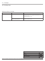
Motor unit Connection Control unit
XB40
(white plug)
<--->
XB40
(white plug)
XP10
(blue plug)
<--->
XP10A
(blue plug)
7. Initial operation

7. Initial operation
Manual for installation and operation, Dynamic xs.plus / FU GB (#89608) 19
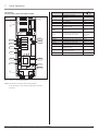
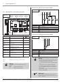
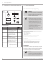
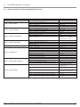
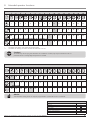
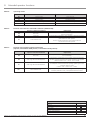
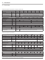
Label Type / function
i
A Positioning box (EPM) –
B
EPM stand-by mode indicator
(LED off)
–
C Operating indicator (EPM) –
D PE connection 7.4
HQ10
Operating voltage indicator for
operator system
7.4 / 2
XB40
Connection of Control x.plus
control unit
7.2 / 4
XH19
Connection of signalling devices
Programmable relay output
7.2 / 7
9.4, Level 1,
Menu 7
XM81A Connection of motor 7.4
XM81B Connection of motor, delta mode 7.4.4
XM89 Connection of brake –
XN81A Connection of mains cable 7.4
XN81B Connection for mains routeing –
XP10
For connection of door sensors
(safety circuit SC)
7.2 / 5
XV30
Connection for RPM sensor
(on the motor side)
–
XV31 Connection for positioning box –
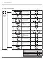
7.2 / 2
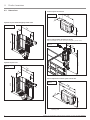
Control unit
Control x.plus 1-phase and 3-phase model
A
B
C
D
EPM: Electronic Positioning Module
XN84: Supplied from factory with shorting jumper.
If this terminal is used, the shorting jumper must be
r emoved.
XP10
XB40
XV31
XV30
HQ10
XM81B
XN81A
XN81B
XM81A
XM89
XH19

Connection of Control x.plus control unit (XB40)
• Insert the plug of the cable loom into terminal XB40 (white
plug).
7.2 / 4
XB40
Connecting for operating controls Control x.plus (XP10)
• Insert the plug of the cable loom into terminal XP10 (blue
plug).
7.2 / 5
XP10
Terminal Configuration
B4 Blue lead
b Red lead
c Black lead
d Violet lead
e Grey/pink lead
f Red/blue lead
7. Initial operation
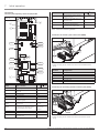
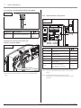
7.2 / 3
Control unit
Control x.plus frequency converter (FU) model
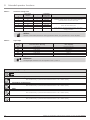
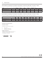
Label Type / function
i
A Positioning box (EPM) –
B
EPM stand-by mode indicator
(LED off)
–
C Operating indicator (EPM) –
D PE connection 7.4
HQ10
Operating voltage indicator for
operator system
7.4 / 2
XB40
Connection of Control x.plus
control unit
7.2 / 4
XH19
Connection of signalling device
Programmable relay output
7.2 / 7
9.4, Level 1,
Menu 7
XN81A Connection of mains cable 7.4
XN81B Connection for mains routeing –
XN85
Connection for frequency
converter (FU)
–
Label Type / function
i
XP10
For connection of door sensors
(safety circuit SC)
7.2 / 5
XV30
Connection for RPM sensor (on
the motor side)
–
XV31 Connection for positioning box –
XW10
Connection for frequency
converter (FU) control cable
–
A
B
C
D
EPM: Electronic Positioning Module
XP10
XB40
XV31
XV30
HQ10
XN85
XN81A
XH19
XN81B
XW10
20 Manual for installation and operation, Dynamic xs.plus / FU GB (#89608)
Page is loading ...
Page is loading ...
Page is loading ...
Page is loading ...
Page is loading ...
Page is loading ...
Page is loading ...
Page is loading ...
Page is loading ...
Page is loading ...
Page is loading ...
Page is loading ...
Page is loading ...
Page is loading ...
Page is loading ...
Page is loading ...
Page is loading ...
Page is loading ...
Page is loading ...
Page is loading ...
Page is loading ...
Page is loading ...
Page is loading ...
Page is loading ...
Page is loading ...
Page is loading ...
Page is loading ...
Page is loading ...
Page is loading ...
Page is loading ...
Page is loading ...
Page is loading ...
Page is loading ...
Page is loading ...
Page is loading ...
Page is loading ...
Page is loading ...
Page is loading ...
Page is loading ...
Page is loading ...
Page is loading ...
Page is loading ...
-
 1
1
-
 2
2
-
 3
3
-
 4
4
-
 5
5
-
 6
6
-
 7
7
-
 8
8
-
 9
9
-
 10
10
-
 11
11
-
 12
12
-
 13
13
-
 14
14
-
 15
15
-
 16
16
-
 17
17
-
 18
18
-
 19
19
-
 20
20
-
 21
21
-
 22
22
-
 23
23
-
 24
24
-
 25
25
-
 26
26
-
 27
27
-
 28
28
-
 29
29
-
 30
30
-
 31
31
-
 32
32
-
 33
33
-
 34
34
-
 35
35
-
 36
36
-
 37
37
-
 38
38
-
 39
39
-
 40
40
-
 41
41
-
 42
42
-
 43
43
-
 44
44
-
 45
45
-
 46
46
-
 47
47
-
 48
48
-
 49
49
-
 50
50
-
 51
51
-
 52
52
-
 53
53
-
 54
54
-
 55
55
-
 56
56
-
 57
57
-
 58
58
-
 59
59
-
 60
60
-
 61
61
-
 62
62


Marantec Dynamic xs.plus Owner's manual
- Type
- Owner's manual
- This manual is also suitable for
Ask a question and I''ll find the answer in the document
Finding information in a document is now easier with AI
Related papers
-
Marantec Dynamic xs.plus FU Owner's manual
-
-
-
-
-
-
Marantec Control 45 Owner's manual
-
Marantec Control 25 Owner's manual
-
Marantec Control 14 Owner's manual
-
Marantec Dynamic 735-S Owner's manual
Other documents
-
 Sargent 2600 Series Instructions For Installation Manual
-
Migipaws B08VHCCP81 User manual
-
 Smart Impulse Smart X User manual
-
VDS BEV 2 User guide
-
Big Ass Fans Basic 6 User manual
-
Sony SRSXB41R User manual
-
 PPA Spin User manual
-
elero BoxControl Compact User manual
-
 Chamberlain Garog DK, DKA Series Owner's manual
-
 AC Tech SV01B User manual


