Page is loading ...

May 2018 UM2245 Rev 2 1/44
1
UM2245
User manual
Sigfox™ software expansion for STM32Cube
Introduction
This user manual describes the Sigfox™ embedded expansion software implementation on
the CMWX1ZZABZ-091 or CMWX1ZZABZ-078 Murata modules. X-CUBE-SFOX is the
name of the corresponding STM32Cube Expansion Package.
This user manual also explains how to interface with the Sigfox™ API from an application
point of view.
Sigfox™ is a type of wireless telecommunication network designed to allow long-range
communication at very low bit rates and enable the use of long-life battery-operated
sensors. The Sigfox Stack™ library from Sigfox™ manages the channel access and
security protocol that ensures interoperability with the Sigfox™ network.
The Sigfox™ software expansion for CMWX1ZZABZ modules is Sigfox Verified™.
X-CUBE-SFOX main features are:
•Application integration ready
•Easy add-on of the low-power LoRa® solution
•Extremely low CPU load
•No latency requirements
•Small STM32 memory footprint
•Low-power timing services provided
The X-CUBE-SFOX software is based on the STM32Cube HAL drivers (refer to Chapter 3:
X-CUBE-SFOX stack description).
This user manual targets the following tool:
•B-L072-LRAWAN1 STM32 Discovery kit embedding the CMWX1ZZABZ-091 module
from Murata. CMWX1ZZABZ-091 embeds the STM32L072 microcontroller.
www.st.com

Contents UM2245
2/44 UM2245 Rev 2
Contents
1 Overview . . . . . . . . . . . . . . . . . . . . . . . . . . . . . . . . . . . . . . . . . . . . . . . . . . 7
1.1 Acronyms and abbreviations . . . . . . . . . . . . . . . . . . . . . . . . . . . . . . . . . . . 7
1.2 Reference . . . . . . . . . . . . . . . . . . . . . . . . . . . . . . . . . . . . . . . . . . . . . . . . . . 7
2 Sigfox™ standard overview . . . . . . . . . . . . . . . . . . . . . . . . . . . . . . . . . . . 8
2.1 Overview . . . . . . . . . . . . . . . . . . . . . . . . . . . . . . . . . . . . . . . . . . . . . . . . . . 8
2.2 End-device hardware architecture . . . . . . . . . . . . . . . . . . . . . . . . . . . . . . . 8
2.3 Regional radio resource . . . . . . . . . . . . . . . . . . . . . . . . . . . . . . . . . . . . . . . 8
2.4 Tx/Rx radio time diagram . . . . . . . . . . . . . . . . . . . . . . . . . . . . . . . . . . . . . . 9
2.5 Listen before talk (LBT) . . . . . . . . . . . . . . . . . . . . . . . . . . . . . . . . . . . . . . 10
3 X-CUBE-SFOX stack description . . . . . . . . . . . . . . . . . . . . . . . . . . . . . . 11
3.1 Overview . . . . . . . . . . . . . . . . . . . . . . . . . . . . . . . . . . . . . . . . . . . . . . . . . .11
3.2 Sigfox™ certification . . . . . . . . . . . . . . . . . . . . . . . . . . . . . . . . . . . . . . . . . .11
3.3 Features . . . . . . . . . . . . . . . . . . . . . . . . . . . . . . . . . . . . . . . . . . . . . . . . . . 12
3.4 Architecture . . . . . . . . . . . . . . . . . . . . . . . . . . . . . . . . . . . . . . . . . . . . . . . 12
3.5 Required STM32 peripherals to drive the radio . . . . . . . . . . . . . . . . . . . . 13
3.5.1 Radio reset . . . . . . . . . . . . . . . . . . . . . . . . . . . . . . . . . . . . . . . . . . . . . . 13
3.5.2 Radio SPI . . . . . . . . . . . . . . . . . . . . . . . . . . . . . . . . . . . . . . . . . . . . . . . . 13
3.5.3 RTC . . . . . . . . . . . . . . . . . . . . . . . . . . . . . . . . . . . . . . . . . . . . . . . . . . . . 13
3.5.4 TIMER2 . . . . . . . . . . . . . . . . . . . . . . . . . . . . . . . . . . . . . . . . . . . . . . . . . 14
3.5.5 Interrupt . . . . . . . . . . . . . . . . . . . . . . . . . . . . . . . . . . . . . . . . . . . . . . . . . 14
4 X-CUBE-SFOX middleware programming guidelines . . . . . . . . . . . . . 15
4.1 Sigfox™ Core library . . . . . . . . . . . . . . . . . . . . . . . . . . . . . . . . . . . . . . . . 15
4.1.1 Opening the library . . . . . . . . . . . . . . . . . . . . . . . . . . . . . . . . . . . . . . . . 16
4.1.2 Sigfox Addon Verified library . . . . . . . . . . . . . . . . . . . . . . . . . . . . . . . . . 16
4.1.3 Sending frames/bits . . . . . . . . . . . . . . . . . . . . . . . . . . . . . . . . . . . . . . . . 17
4.1.4 Set standard configuration for FH . . . . . . . . . . . . . . . . . . . . . . . . . . . . . 17
4.2 Library Sigfox™ modulation . . . . . . . . . . . . . . . . . . . . . . . . . . . . . . . . . . . 19
4.3 Cmac library . . . . . . . . . . . . . . . . . . . . . . . . . . . . . . . . . . . . . . . . . . . . . . . 21
4.4 Credentials library . . . . . . . . . . . . . . . . . . . . . . . . . . . . . . . . . . . . . . . . . . 21
4.5 Utilities . . . . . . . . . . . . . . . . . . . . . . . . . . . . . . . . . . . . . . . . . . . . . . . . . . . 22

UM2245 Rev 2 3/44
UM2245 Contents
4
4.5.1 Timer server . . . . . . . . . . . . . . . . . . . . . . . . . . . . . . . . . . . . . . . . . . . . . . 22
4.5.2 Low-power manager . . . . . . . . . . . . . . . . . . . . . . . . . . . . . . . . . . . . . . . 23
4.5.3 Scheduler . . . . . . . . . . . . . . . . . . . . . . . . . . . . . . . . . . . . . . . . . . . . . . . . 23
4.6 EEPROM driver . . . . . . . . . . . . . . . . . . . . . . . . . . . . . . . . . . . . . . . . . . . . 24
4.7 Memory section . . . . . . . . . . . . . . . . . . . . . . . . . . . . . . . . . . . . . . . . . . . . 25
5 Application description . . . . . . . . . . . . . . . . . . . . . . . . . . . . . . . . . . . . . 26
5.1 Hardware . . . . . . . . . . . . . . . . . . . . . . . . . . . . . . . . . . . . . . . . . . . . . . . . . 26
5.2 Package description . . . . . . . . . . . . . . . . . . . . . . . . . . . . . . . . . . . . . . . . . 26
5.3 AT modem Application . . . . . . . . . . . . . . . . . . . . . . . . . . . . . . . . . . . . . . . 28
5.3.1 UART interface . . . . . . . . . . . . . . . . . . . . . . . . . . . . . . . . . . . . . . . . . . . 28
5.3.2 Default parameters . . . . . . . . . . . . . . . . . . . . . . . . . . . . . . . . . . . . . . . . 28
5.3.3 AT? to list the available commands . . . . . . . . . . . . . . . . . . . . . . . . . . . . 29
5.3.4 AT$RFS to restore factory settings . . . . . . . . . . . . . . . . . . . . . . . . . . . . 29
5.3.5 AT$ID to get the device ID . . . . . . . . . . . . . . . . . . . . . . . . . . . . . . . . . . . 29
5.3.6 AT$PAC to get the device PAC . . . . . . . . . . . . . . . . . . . . . . . . . . . . . . . 29
5.3.7 AT$SB to send a bit status . . . . . . . . . . . . . . . . . . . . . . . . . . . . . . . . . . . 29
5.3.8 AT$SF to send the payload in bytes . . . . . . . . . . . . . . . . . . . . . . . . . . . 30
5.3.9 ATS410 to set AES key . . . . . . . . . . . . . . . . . . . . . . . . . . . . . . . . . . . . . 31
5.3.10 ATS300 to send an out-of-band message once . . . . . . . . . . . . . . . . . . 31
5.3.11 ATS302 to set the radio output power . . . . . . . . . . . . . . . . . . . . . . . . . . 31
5.3.12 AT$CW continuous wave . . . . . . . . . . . . . . . . . . . . . . . . . . . . . . . . . . . . 32
5.3.13 AT$PN PRBS9 continuous Tx wave . . . . . . . . . . . . . . . . . . . . . . . . . . . 32
5.3.14 AT$TM Sigfox™ test mode . . . . . . . . . . . . . . . . . . . . . . . . . . . . . . . . . . 33
5.3.15 AT$RSSICAL to set and get the RSSI calibration . . . . . . . . . . . . . . . . . 34
5.3.16 AT$RC to set/get the zones . . . . . . . . . . . . . . . . . . . . . . . . . . . . . . . . . . 34
5.3.17 ATS400 to configure specific variables for standard . . . . . . . . . . . . . . . 35
5.4 Push-button application . . . . . . . . . . . . . . . . . . . . . . . . . . . . . . . . . . . . . . 35
5.5 Signature generator . . . . . . . . . . . . . . . . . . . . . . . . . . . . . . . . . . . . . . . . . 36
5.6 Static switches . . . . . . . . . . . . . . . . . . . . . . . . . . . . . . . . . . . . . . . . . . . . . 36
5.6.1 Debug switch . . . . . . . . . . . . . . . . . . . . . . . . . . . . . . . . . . . . . . . . . . . . . 36
5.6.2 Sensor switch . . . . . . . . . . . . . . . . . . . . . . . . . . . . . . . . . . . . . . . . . . . . 36
5.6.3 Disable low-power switch . . . . . . . . . . . . . . . . . . . . . . . . . . . . . . . . . . . 36
5.7 Personalization and activation . . . . . . . . . . . . . . . . . . . . . . . . . . . . . . . . . 37
5.7.1 Personalization . . . . . . . . . . . . . . . . . . . . . . . . . . . . . . . . . . . . . . . . . . . 39
5.7.2 Activation . . . . . . . . . . . . . . . . . . . . . . . . . . . . . . . . . . . . . . . . . . . . . . . . 40

Contents UM2245
4/44 UM2245 Rev 2
6 System performance . . . . . . . . . . . . . . . . . . . . . . . . . . . . . . . . . . . . . . . . 41
6.1 Memory footprint . . . . . . . . . . . . . . . . . . . . . . . . . . . . . . . . . . . . . . . . . . . 41
6.2 Real-time constraints . . . . . . . . . . . . . . . . . . . . . . . . . . . . . . . . . . . . . . . . 41
6.3 Power consumption . . . . . . . . . . . . . . . . . . . . . . . . . . . . . . . . . . . . . . . . . 42
7 Revision history . . . . . . . . . . . . . . . . . . . . . . . . . . . . . . . . . . . . . . . . . . . 43

UM2245 Rev 2 5/44
UM2245 List of tables
5
List of tables
Table 1. List of acronyms and abbreviations . . . . . . . . . . . . . . . . . . . . . . . . . . . . . . . . . . . . . . . . . . . 7
Table 2. Region country list . . . . . . . . . . . . . . . . . . . . . . . . . . . . . . . . . . . . . . . . . . . . . . . . . . . . . . . . 8
Table 3. Region configuration RF parameters . . . . . . . . . . . . . . . . . . . . . . . . . . . . . . . . . . . . . . . . . . 8
Table 4. Timings . . . . . . . . . . . . . . . . . . . . . . . . . . . . . . . . . . . . . . . . . . . . . . . . . . . . . . . . . . . . . . . . 10
Table 5. Application level Sigfox™ APIs. . . . . . . . . . . . . . . . . . . . . . . . . . . . . . . . . . . . . . . . . . . . . . 15
Table 6. Sigfox Addon Verified library . . . . . . . . . . . . . . . . . . . . . . . . . . . . . . . . . . . . . . . . . . . . . . . 16
Table 7. Macro channel mapping . . . . . . . . . . . . . . . . . . . . . . . . . . . . . . . . . . . . . . . . . . . . . . . . . . . 17
Table 8. Cmac primary APIs . . . . . . . . . . . . . . . . . . . . . . . . . . . . . . . . . . . . . . . . . . . . . . . . . . . . . . . 21
Table 9. Credentials primary APIs . . . . . . . . . . . . . . . . . . . . . . . . . . . . . . . . . . . . . . . . . . . . . . . . . . 21
Table 10. Timer server APIs . . . . . . . . . . . . . . . . . . . . . . . . . . . . . . . . . . . . . . . . . . . . . . . . . . . . . . . . 22
Table 11. Low-power APIs . . . . . . . . . . . . . . . . . . . . . . . . . . . . . . . . . . . . . . . . . . . . . . . . . . . . . . . . . 23
Table 12. Low-power modes . . . . . . . . . . . . . . . . . . . . . . . . . . . . . . . . . . . . . . . . . . . . . . . . . . . . . . . 23
Table 13. Scheduler APIs . . . . . . . . . . . . . . . . . . . . . . . . . . . . . . . . . . . . . . . . . . . . . . . . . . . . . . . . . . 24
Table 14. EEPROM APIs . . . . . . . . . . . . . . . . . . . . . . . . . . . . . . . . . . . . . . . . . . . . . . . . . . . . . . . . . . 24
Table 15. Memory footprint measured values . . . . . . . . . . . . . . . . . . . . . . . . . . . . . . . . . . . . . . . . . . 41
Table 16. Document revision history . . . . . . . . . . . . . . . . . . . . . . . . . . . . . . . . . . . . . . . . . . . . . . . . . 43

List of figures UM2245
6/44 UM2245 Rev 2
List of figures
Figure 1. Timing diagram for uplink only . . . . . . . . . . . . . . . . . . . . . . . . . . . . . . . . . . . . . . . . . . . . . . . 9
Figure 2. Timing diagram for uplink with downlink . . . . . . . . . . . . . . . . . . . . . . . . . . . . . . . . . . . . . . . . 9
Figure 3. Firmware top-level structure . . . . . . . . . . . . . . . . . . . . . . . . . . . . . . . . . . . . . . . . . . . . . . . . 12
Figure 4. Dual buffer modulation with STM32 . . . . . . . . . . . . . . . . . . . . . . . . . . . . . . . . . . . . . . . . . . 20
Figure 5. Memory mapping . . . . . . . . . . . . . . . . . . . . . . . . . . . . . . . . . . . . . . . . . . . . . . . . . . . . . . . . 25
Figure 6. B-L072-LRAWAN1 configuration . . . . . . . . . . . . . . . . . . . . . . . . . . . . . . . . . . . . . . . . . . . . 26
Figure 7. Package overview. . . . . . . . . . . . . . . . . . . . . . . . . . . . . . . . . . . . . . . . . . . . . . . . . . . . . . . . 27
Figure 8. Tera Term serial port setup . . . . . . . . . . . . . . . . . . . . . . . . . . . . . . . . . . . . . . . . . . . . . . . . 28
Figure 9. Sigfox™ personalization and activation overview. . . . . . . . . . . . . . . . . . . . . . . . . . . . . . . . 38

UM2245 Rev 2 7/44
UM2245 Overview
43
1 Overview
The X-CUBE-SFOX STM32Cube Expansion Package runs on STM32 32-bit
microcontrollers based on the Arm®(a) Cortex®-M processor.
1.1 Acronyms and abbreviations
1.2 Reference
1. B-L072Z-LRWAN1 Discovery kit technical documentation such as the Discovery kit for
LoRaWAN™ and LPWAN protocols with STM32L0 data brief (DB3090) available on
the www.st.com web site
2. Sigfox™ Radio Signal Analyzer User guide available on https://resources.sigfox.com
a. Arm is a registered trademark of Arm Limited (or its subsidiaries) in the US and/or elsewhere.
Table 1. List of acronyms and abbreviations
Term Definition
DC Duty cycle
FH Frequency hopping
LBT Listen before talk
NA Not applicable
RC Regional configuration
RSSI Received signal strength indication
Rx Reception
SDR Software defined radio
Tx Transmission

Sigfox™ standard overview UM2245
8/44 UM2245 Rev 2
2 Sigfox™ standard overview
2.1 Overview
This section provides a general overview of Sigfox™ focusing in particular Sigfox™ end-
device which is the core subject of this user manual.
Sigfox™ is a wireless telecommunication Network operator designed to allow long range
communication at a low bit-rate enabling long-life battery operated sensors. The Sigfox™
software expansion includes the Sigfox Stack™ library delivered by Sigfox™. The Sigfox™
software expansion named X-CUBE-SFOX loaded on B-L072Z-LRWAN1 is Sigfox
Verified™.
Sigfox™ limits the use of its network to 144 messages per day and per device. Each
message can be from 1 bit up to 12 bytes.
2.2 End-device hardware architecture
The end-device is made of an RF transceiver (also known as radio) and a host STM32L072.
The RF transceiver is composed of a modem and an RF up-converter. The built-in
modulator does not support Sigfox™ BPSK modulation; therefore it is implemented inside
the STM32L072.
The STM32L072 implements the radio driver, the Sigfox™ modulator, the Sigfox Stack™
libraries and the application layer.
2.3 Regional radio resource
The European, North American and Asian markets have different spectrum allocations and
regulatory requirements. Sigfox™ has split requirements in Region Configurations (RC) as
listed in Table 2.
Table 3 provides an overview of the regulatory requirements for the region configurations.
Table 2. Region country list
Region configuration Country
RC1 Europe countries, Oman, Lebanon, South Africa, Kenya
RC2 USA, Canada, Mexico
RC3c Japan
RC4 Brazil, Colombia, Peru, New–Zealand, Australia, and Singapore
Table 3. Region configuration RF parameters
Parameters RC1 RC2 RC3c RC4
Frequency band downlink (MHz) 869.525 905.2 922.2 922.3
Frequency band uplink (MHz) 868.130 902.2 923.2 920,8
Uplink modulation DBPSK DBPSK DBPSK DBPSK

UM2245 Rev 2 9/44
UM2245 Sigfox™ standard overview
43
2.4 Tx/Rx radio time diagram
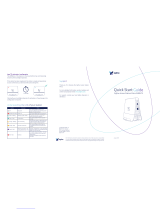
The end-device transmits data to the network in an asynchronous manner. This is due to the
fact that transmission data is only sent per device-report event. Figure 1 and Figure 2 depict
the timing sequences with and without a downlink.
Note: The presence of a downlink only depends on device configuration.
The three transmissions Tx1, Tx2 and Tx3 contain the same payload information. These
consecutive transmissions only maximize the probability of a correct reception by the
network. When the device observes good link quality to the network, it may decide to send
only Tx1 to save power consumption only if downlink frame is requested. The API to select
preferred scheme is described in Section 4.1.3: Sending frames/bits on page 17.
Figure 1. Timing diagram for uplink only
Figure 2. Timing diagram for uplink with downlink
Downlink modulation GFSK GFSK GFSK GFSK
Uplink data-rate 100 600 100 600
Downlink data-rate 600 600 600 600
Max output power (dBm) 14 22 13 22
Medium access Duty cycle 1%
Frequency
hopping
Max On time
400 ms / 20 s
Carrier sense
Frequency
hopping
Max On time
400 ms / 20 s
CS center frequency (MHz) NA NA 923.2 NA
CS bandwidth (kHz) NA NA 200 NA
Table 3. Region configuration RF parameters (continued)
Parameters RC1 RC2 RC3c RC4
06Y9
7[ 7[ 7[
,QWHUIUDPH7[ ,QWHUIUDPH7[
(QGWLPHRXW
,QWHUIUDPH7[
06Y9
7[
,QWHUIUDPH75[
6WDUW7[
GHOD\
7[ 7[ 5[ZLQGRZ 7[22%
5[GHOD\
22%B$&.
GHOD\
5[WLPHRXW
,QWHUIUDPH75[

Sigfox™ standard overview UM2245
10/44 UM2245 Rev 2
The timings shown in Figure 1 and Figure 2 are given in Table 4 for the various regional
configurations.
The Tx periods depend on the number of bytes sent and on the RC zone:
•It takes 10 ms to send a bit in RC1 and RC3c.
•It takes 1.66 ms to send a bit in RC2 and RC4.
A message can be 26-byte long at the most (including sync word, header, and payload
data). Therefore, for RC1, a Tx period can be maximum 26 x 8 x 10 ms = 2.08 s.
2.5 Listen before talk (LBT)
In RC3c, LBT is mandatory before any transmission. The device must listen and check if the
channel is free. The channel is considered as free if the power within a 200 kHz bandwidth
stays below -80 dBm for 5 ms.
When the channel is free, the device starts a transmission. The transmission is not started
otherwise.
Table 4. Timings
StartTx delay Interframe Tx/TRx Rx delay Rx timeout OOB_ACK
delay
End
timeout
RC1 0 s 500 ms 20 s 25 s 1.4 s NA
RC2 0 s 500 ms 20 s 25 s 1.4 s 10 s
RC3c 100 ms max (LBT) 500 ms + LBT 19 s 34 s 1.4 s NA
RC4 0 s 500 ms 20 s 25 s 1.4 s 10 s

UM2245 Rev 2 11/44
UM2245 X-CUBE-SFOX stack description
43
3 X-CUBE-SFOX stack description
3.1 Overview
The X-CUBE-SFOX package contains:
•The Sigfox™ middleware
•The board support package composed of:
– B-L072-LRAWAN1 Discovery board drivers
– CMWX1ZZABZ Murata module drivers (MLM32L07X01)
– sx1276 radio drivers
– Sensor ST drivers
•The CMSIS and STM32L0xx HAL drivers
•Two Sigfox™ application examples
The Sigfox™ middleware for STM32 microcontrollers is split into several modules:
•Sigfox™ Core library
•Sigfox™ Addon Library (for Sigfox™ testing purpose)
•Sigfox™ Cmac Library, which manages frame security
•Sigfox™ utilities module (such as timer server, power management and scheduler)
The application layer, which hosts the two examples Sgfx_ModemAT and
SGfx_push_button, includes a specific common directory for the CMWX1ZZABZ Murata
module with:
•The Sigfox™ modulation library for the sx1276 radio
•The Credentials library, which manages Sigfox™ credentials for the module
The Sigfox™ Core library implements a Sigfox™ medium access controller from Sigfox™. It
interfaces with the Cmac library encrypting uplink payload and verifying downlink payload.
The Cmac library interfaces with the Credentials library holding the cryptographic functions.
It also interfaces with the lower layer Sigfox™ modem designed to drive the sx1276 radio.
The Sigfox™ library, cryptographic library and modem library modules are provided as
compiled objects.
Figure 7 on page 27 provides an overview of the structure of the project files.
3.2 Sigfox™ certification
The Sigfox Addon Verified library, as well as the RF_API and MCU_API, have been verified
by Sigfox™ Test Lab. Nevertheless, the end product based on the CMWX1ZZABZ module
must pass the Sigfox Ready™ certification before its commercialization.

X-CUBE-SFOX stack description UM2245
12/44 UM2245 Rev 2
3.3 Features
The X-CUBE-SFOX package main features are:
•Sigfox Verified™
•RC1, RC2, RC3c, and RC4 support
•Low-power optimization
•Low real-time constraints even during modulation
•Support of the CMWX1ZZABZ-091 module
3.4 Architecture
Figure 3 depicts the top-level firmware structure of the X-CUBE-SFOX application.
Figure 3. Firmware top-level structure
The HAL uses cube API to drive the STM32L072 hardware required by the application.
The RTC provides a centralized time unit that continues to run even in the low-power Stop
mode. The RTC alarm is used to wake up the system at specific times managed by the timer
server.
06Y9
$SSOLFDWLRQOD\HU
6LJIR[0RGXODWLRQOLEUDU\
//UDGLRGULYHU
+$/
6LJIR[SURSULHWDU\
,&
8WLOLWLHV
%63
VHQVRU
GULYHU
/LEUDU\
&PDF
7LPH6HUYHU
6FKHGXOHU
/RZ3RZHU
PDQDJHU
((3520
VWORZ/HYHOF
6LJIR[$GGRQ9HULILHG
OLEUDU\
*3,2 63, 57& $'& 7,0
VLJIR[BDSLK
VWORZ/HYHOK
UDGLRK
/HJHQG 5DGLRVSHFLILF6LJIR[GHYLFHVSHFLILF /LEUDULHV
6LJIR[&RUHOLEUDU\
UIBDSLFPFXBDSLF
/LEUDU\
&UHGHQWLDOV
VHBDSLK PFXBDSLK UIBDSLK

UM2245 Rev 2 13/44
UM2245 X-CUBE-SFOX stack description
43
The radio driver uses the SPI and the GPIO HW (as shown in Figure 3) to control the radio,
it also provides a set of API to be used by higher level software. Only the low level radio
driver is used in X-CUBE-SFOX. The radio driver is split in two parts:
•The \BSP\Components\sx1276\sx1276.c file contains all functions which are radio
component dependent only.
•The \BSP\MLM32L07X01\mlm32l07x01.c file contain all the radio module dependent
functions.
Note: The sx1276.c and the mlm32l07x01.c files are the same as in the I-CUBE-LRWAN package.
The Common\cwmx1zzabz\Radio_Sigfox_Driver\st-lowlevel.c file implements the interface
between library Sigfox™ modulation SgfxSTModemSx1276V123_CM0_IDE_O3.lib and the
sx1276 radio driver. It also interfaces interrupt to the handler function.
mcu_api.c interfaces with non-volatile memory to save data in EEPROM, and implements
the timer management and energy-efficient wait function.
The Sigfox™ modulation library is called by rf_api.c. It starts and stops the radio using the
proper Tx and Rx configuration. It implements the modulation using the double buffer DMA
to relax timing constraints on the modulation. This library is radio dependent. More
information is provided in Section 4.2: Library Sigfox™ modulation on page 19.
The Sigfox™ Core library embeds the medium access controller (MAC). More information is
provided in Section 4.1: Sigfox™ Core library on page 15.
The application is built around an infinite loop including a scheduler. The scheduler process
tasks and events. When nothing remains to be done, the scheduler transitions to idle state
and calls the low-power manager.
A typical application can be for instance:
•an AT layer to interface with external Host (refer to Section 3.4: Architecture)
•any application reading and sending sensor data upon an action (refer to Section 5.4:
Push-button application on page 35)
3.5 Required STM32 peripherals to drive the radio
3.5.1 Radio reset
One MCU GPIO f is used to reset the radio. A reset of the radio is performed before any
radio activity.
3.5.2 Radio SPI
The sx1276 radio registers are accessed through the SPI bus at 8 Mbps.
Radio NSS is controlled in two ways: during Tx modulation periods, the NSS pin is set as an
alternate function and mapped on Timer2 output compare; the rest of the time, it is set by
software through a GPIO.
3.5.3 RTC
The RTC calendar is used as 32-bit counter running in all power modes from the 32 kHz
external oscillator. By default, it is programed to provide 1024 ticks (sub-seconds) per
second. It is programed once at the initialization of the hardware when the STM32L072

X-CUBE-SFOX stack description UM2245
14/44 UM2245 Rev 2
starts for the first time. Its output is limited to a 32-bit timer which corresponds to about a
48-day period.
Caution: When changing the tick duration, the user shall keep it below 1ms.
3.5.4 TIMER2
It is used during the modulation (Tx mode). It is used as NSS source and triggers the DMA
to transfer data to the SPI peripheral. This ensures phase synchronization between the SPI
NSS state and SPI data, and allows the Arm® core to enter the Sleep mode while
modulation data is sent to the radio.
3.5.5 Interrupt
In the Tx mode, the DMA interrupt has the highest priority. All other interrupts must be lower-
level interrupts to ensure proper Sigfox™ transmit mask.
Note: In the Tx mode, no interrupt line is needed.
In the Rx mode, two radio interrupt lines are dedicated to receive the interrupts from the
radio.
•DIO0 is used to signal that the LoRa® radio has successfully received a radio packet
(RxDone)
•DIO4 is used to signal that the radio has successfully detected a synchronization, and
therefore that the STM32 can read RSSI.
The priority levels are defined in file hw_conf.h.

UM2245 Rev 2 15/44
UM2245 X-CUBE-SFOX middleware programming guidelines
43
4 X-CUBE-SFOX middleware programming guidelines
4.1 Sigfox™ Core library
Embedded applications using the Sigfox™ Core library call SIGFOX_APIs to manage
communication. The content of SIGFOX_APIs is described in Table 5.
Table 5. Application level Sigfox™ APIs
Function Description
sfx_error_t SIGFOX_API_get_device_id
(sfx_u8 *dev_id);
Copies the ID of the device to the pointer given in
parameter.
The ID is 4-byte long and in binary format.
sfx_error_t SIGFOX_API_get_initial_pac
(sfx_u8 *initial_pac);
Gets the value of the PAC stored in the device. This
value is used when the device is registered for the first
time on the backend.
The PAC is 8-byte long.
sfx_error_t SIGFOX_API_open
(sfx_rc_t *rc);
Initializes the library. It saves the input parameters once
(cannot be changed until SIGFOX_API_close() is
called)
–rc: pointer on the radio configuration zone. It is
mandatory to use already existing defined RCs.
sfx_error_t SIGFOX_API_close
(void); Closes the library and stops the RF.
sfx_error_t SIGFOX_API_send_frame
(sfx_u8 *customer_data, sfx_u8
customer_data_length,
sfx_u8 *customer_response, sfx_u8
tx_repeat,
sfx_bool initiate_downlink_flag);
Sends a standard Sigfox™ frame with customer
payload.
–customer_data: payload cannot exceed 12 bytes.
–customer_data_length: length in bytes.
–customer_response: received response.
–tx_repeat: when 0, sends one Tx, when 1, sends
three Tx.
–initiate_downlink_flag: if set, the frame sent is
followed by a receive downlink frame and an out-of-
band Tx frame (voltage, temperature and RSSI).

X-CUBE-SFOX middleware programming guidelines UM2245
16/44 UM2245 Rev 2
Secondary APIs are described in sigfox_api.h. The library can be found in directory
Middlewares\Third_Party\SigfoxLib.
4.1.1 Opening the library
ST_SIGFOX_API_open must be called to initialize the library before any other operation is
performed.
This API requires the RC argument number representing the radio configuration zone. Refer
to Section 2.3: Regional radio resource on page 8 for details.
For radio control zones 2 and 4, FCC requires frequency hopping so the transmission
frequency won't be fixed. Refer to Section 4.1.4: Set standard configuration for FH for the
mapping of the macro channels.
4.1.2 Sigfox Addon Verified library
This library is used to test the device for Sigfox Verified™ certification. Ultimately, this library
can be removed from the build once certified. The content of the Sigfox Addon Verified
library is described in Table 6.
This library is located in Middlewares\Third_Party\Sgfx\SigfoxLibTest\.
sfx_error_t SIGFOX_API_send_bit
(sfx_bool bit_value, sfx_u8
*customer_response,
sfx_u8 tx_repeat, sfx_bool
initiate_downlink_flag);
Sends a standard Sigfox™ frame with null customer
payload. This frame is the shortest frame that Sigfox™
library can generate.
–bit_value: bit sent.
–customer_response: received response.
–tx_repeat: when 0, sends one Tx, when 1, sends
three Tx.
–initiate_downlink_flag: if set, the frame sent is
followed by a receive downlink frame and an out-of-
band Tx frame (voltage, temperature and RSSI).
sfx_error_t SIGFOX_API_set_std_config
(sfx_u32 config_words[3], sfx_bool
timer_enable);
Configures specific variables for standard.
Parameters have different meanings whether in FH or
LBT mode.
Note: this function has no influence in DC.
See Section 5.3.17: ATS400 to configure specific
variables for standard on page 35 for details.
Table 5. Application level Sigfox™ APIs (continued)
Function Description
Table 6. Sigfox Addon Verified library
Function Description
sfx_error_t
ADDON_SIGFOX_VERIFIED_API_test_mode(sfx_rc
_enum_t rc_enum, sfx_test_mode_t
test_mode);
Executes the test modes needed for the Sigfox
Verified™ certification:
–rc_enum: rc at which the test mode is run.
–test_mode: test mode to run.

UM2245 Rev 2 17/44
UM2245 X-CUBE-SFOX middleware programming guidelines
43
4.1.3 Sending frames/bits
ST_SIGFOX_API_send_frame is the main Sigfox™ library function. This blocking function
handles message exchange between the end node and the base stations. An important
parameter of this function is the initiate_downlink_flag which selects different transmission
behaviors:
•When the initiate_downlink_flag is 0, the library requests only uplink frame. The sent
frame is transmitted once if tx_repeat equal to 0, or three times if tx_repeat is different
from 0 with a 500 ms pause.(refer to Figure 1 on page 9).The transmit payload can be
maximum 12-byte long.
•When the initiate_downlink_flag is 1, the frame to be sent is transmitted three times
with a 500 ms pause. A 25 s Rx window then opens 20 s after the end of the first
repetition (Figure 2 on page 9 illustrates such a sequence).
If the reception is successful, the received 8-byte downlink frame is stored in the buffer
location indicated by the customer_response buffer.
4.1.4 Set standard configuration for FH
The FCC allows the transmitters to choose certain macro channels to implement a
frequency hopping pattern authorized by the standard. The channel map is specified in the
first argument of SIGFOX_API_set_std_config, which consists of an array of three 32-bit
configuration words.
A macro-channel consists of 6 micro channels centered about the center frequency of the
macro channel and separated by 25 kHz. For example, in the 902.2 MHz macro channel,
the 6 micro channels are 902.1375 MHz, 902.1625 MHz, 902.1875 MHz, 902.2125 MHz,
902.2375 MHz, and 902.2625 MHz.
A typical Sigfox™ frame lasts between 200 ms and 350 ms at 600 bps, and FCC mandates
a max dwell time of 400 ms. A transmitter cannot return to a given channel before 20 s.
Therefore, at least 20 / 0.4 = 50 channels must be used for continuous transmission.
Actually, a device only transmits a few frames per day (144 messages maximum). Enabling
one macro channel only and inserting 10-s delays between 2 groups of 3 repeated frames
(1 frame per micro channel means 6 micro channels) pass the regulation limits.
Each bit of the config_words[0,1,2] array represents a macro channel according to the
mapping described in Table 7.
Table 7. Macro channel mapping
Bit
config_words[0]
Frequency mapping
(MHz)
config_words[1]
Frequency mapping
(MHz)
config_words[2]
Frequency mapping
(MHz)
0 902.2 911.8 921.4
1 902.5 912.1 921.7
2 902.8 912.4 922
3 903.1 912.7 922.3
4 903.4 913 922.6
5 903.7 913.3 922.9
6 904 913.6 923.2

X-CUBE-SFOX middleware programming guidelines UM2245
18/44 UM2245 Rev 2
A macro channel is only enabled when the corresponding config_words[] bit is set to 1. For
example, bit 0 of config word[0] corresponds to channel 1 while bit 30 of config_word[1]
corresponds to channel 63. At least nine macro channels must be enabled to meet the FCC
specifications.
Long message configuration example:
•config_words[0] = [0x0000 01FF]
•config_words[1] = [0x0000 0000]
•config_words[2] = [0x0000 0000]
7 904.3 913.9 923.5
8 904.6 914.2 923.8
9 904.9 914.5 924.1
10 905.2 914.8 924.4
11 905.5 915.1 924.7
12 905.8 915.4 925
13 906.1 915.7 925.3
14 906.4 916 925.6
15 906.7 916.3 925.9
16 907 916.6 926.2
17 907.3 916.9 926.5
18 907.6 917.2 926.8
19 907.9 917.5 927.1
20 908.2 917.8 927.4
21 908.5 918.1 927.7
22 908.8 918.4 928
23 909.1 918.7 928.3
24 909.4 919 928.6
25 909.7 919.3 928.9
26 910 919.6 929.2
27 910.3 919.9 929.5
28 910.6 920.2 929.8
29 910.9 920.5 930.1
30 911.2 920.8 930.4
31 911.5 921.1 930.7
Table 7. Macro channel mapping (continued)
Bit
config_words[0]
Frequency mapping
(MHz)
config_words[1]
Frequency mapping
(MHz)
config_words[2]
Frequency mapping
(MHz)

UM2245 Rev 2 19/44
UM2245 X-CUBE-SFOX middleware programming guidelines
43
In this example, channels 1 to 9 are enabled with frequencies ranging from 902.2 MHz to
904.6 MHz.
By default the X-CUBE-SFOX sets one macro channel with timer_enable set to 1. Macro
channel 1 in RC2 (operational frequency is 902.2 MHz) and macro channel 63 in RC4
(operational frequency is 920.8 MHz). This is the short message configuration operational
for Sigfox™ (see defined value RCx_SM_CONFIG in sigfox_api.h).
A delay (timer_enable) is implemented to avoid one micro channel to be re used with an
interval lower than 20 s. When using one macro channel only (6 micro channels) performing
3 repetitions, this delay corresponds to 10 s. When using two macro channels (12 micro
channels) the delay automatically becomes 5 s.
For certification test purposes, timer_enable may be set to 0, but shall be set to 1 otherwise.
The default settings can nevertheless be modified using the ATS400 command (refer to
Section 5.3.17: ATS400 to configure specific variables for standard on page 35) to speed up
the certification process.
4.2 Library Sigfox™ modulation
The library is used to configure the radio in the transmit or receive mode. It also provides the
interface to the STM32 hardware such as time, interrupts and the sx1276 radio.
This library is radio specific. It can therefore only be used with sx1276 Semtech Radio.
The DMA is used to let the real time modulation run with minimum real time constraint.
Indeed, a bit in RC1 lasts 10 ms and a bit in RC2 and RC4 lasts 1.66 ms. The modulator
needs to send around 800 samples through to the radio to respect the Sigfox™ spectrum
specification and claim for certification. Therefore, the worst case requirement in RC2 is
2 μs per sample. To decrease real time constraints, the STM32L0 prepares bit N+1 (write
samples in memory) while the DMA sends samples for bit N to the SPI peripheral.
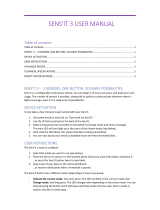
By using a double buffer technique, bit N+1 can be prepared in memory page (N+1)%2
while bit N is being sent from memory page (N)%2, and so forth. This is illustrated in
Figure 4.

X-CUBE-SFOX middleware programming guidelines UM2245
20/44 UM2245 Rev 2
Figure 4. Dual buffer modulation with STM32
The Trun duration is approximately 430 μs. Each bit preparation can be delayed by Tsleep
in the worst case. During the Tsleep duration, the STM32 is in the Sleep mode and the Arm®
clock is switched off.
Timer 2 is used to:
•Trigger the DMA transfer from the memory to the SPI data register
•Generate the NSS from output compare (OC)
In summary, the microcontroller is only active during 430 μs for each bit sent. It can sleep or
serve other routines the rest of the time.
The modulation library is located in directory Projects\B-L072Z-
LRWAN1\Applications\Sgfx\Common\cwmx1zzabz\Radio_Sigfox_Driver\.
%LW %LW %LW %LW
PVLQ5&
PVLQRWKHU]RQHV
%LWUHDGE\'0$ %LW %LW %LW%LW
UXQ
670WR
PHPRU\
VOHHS
3UHSD
UHV
%LW
3UHSD
UHV
%LW
3UHSD
UHV
%LW
3UHSD
UHV
%LW
%LWRQDLU
3UHSD
UHV
%LW
SDJH SDJH SDJH SDJH SDJH0HPRU\ZULWWHQ
SDJH SDJH SDJH SDJH0HPRU\UHDGE\'0$
7UXQ 7VOHHS
06Y9
/