daviteq WSSFC-V1A User guide

Type
User guide

The daviteq WSSFC-V1A is a Sigfox-enabled vibration sensor designed for condition monitoring and preventive maintenance applications, featuring a cost-effective design and single-axis vibration measurement capabilities. With its hermetically sealed piezo-ceramic crystal and low-power electronics, it offers reliable and stable output for long-term monitoring.

The device excels in machine health monitoring, providing superior resolution, dynamic range, and bandwidth compared to MEMS devices. It combines vibration measurement with temperature sensing, allowing users to monitor both vibration levels and temperature at the mounting point.

WSSFC-V1A-MN-EN-01
MAY-2021
SKU
WSSFC-V1A
HW Ver.
1.1
FW Ver.
1.0
Item Code
WSSFC-V1A-9-01
SIGFOX PIEZO-ELECTRIC 10KHZ VIBRATION SENSOR, +/- 25G, INTERNAL ANTENNA, TYPE AA
BATTERY 1.5VDC, IP67, RC2-RC3-RC4-RC5 ZONES
WSSFC-V1A-8-01
SIGFOX PIEZO-ELECTRIC 10KHZ VIBRATION SENSOR, +/- 25G, INTERNAL ANTENNA, TYPE AA
BATTERY 1.5VDC, IP67, RC1-RC6-RC7 ZONES
STEP 1: Select RC
1. Select RC zone using Modbus Configuration Cable
RC zones selection 1, 2, 4 is RCZ1, RCZ2, RCZ4 (refer to register
address 270)
2. Select RC zone using button
Refer to the button configuration
USER GUIDE FOR SIGFOX PIEZO-
ELECTRIC 10KHZ VIBRATION
SENSOR WSSFC-V1A
This document is applied for the following products
0. Configuration Check List
STEP 2: Check ID and PAC
Use Modbus Configuration Cable to read the ID and PAC values
Refer to register address 8 and 10 (DEC)
STEP 3: Configure the sensor's operating parameters
Configure parameters like cycle send data, alarm, a, b,...
Refer to the configuration section using the Modbus Configuration
Cable
STEP 4: Add device to Backend Sigfox
refer to section 5.4 for details
HW Ver.
FW Ver.
Release Date
Functions Change
1.1
1.0
DEC-2020
WSSFC-V1A is a cost effective, Sigfox accelerometer single-axis vibration sensor designed for condition monitoring and
preventive maintenance applications. The piezo-electric accelerometer is available in ranges ±25g or 50g and features
a flat frequency response up to >10kHz. Its accelerometer feature a stable piezo-ceramic crystal in shear mode with
low power electronics, sealed in a fully hermetic package. The Piezo Electric technology incorporated in the WSSCF-V1A
accelerometer has a proven track record for offering the reliable and long-term stable output required for condition
monitoring applications. The accelerometer is designed and qualified for machine health monitoring and has superior
Resolution, Dynamic Range and Bandwidth to MEMS devices. Beside that it can also measure the temperature at
mounting point. With Ultra-low power design and smart firmware allow the complete Wireless and Sensor package run
on 2 x AA battery up to 10 years. It can support all regions of Sigfox network in over the World, RC1, RC2, RC3, RC4,
RC5, RC6, RC7.
SENSOR SPECIFICATION
1. Functions Change Log
2. Introduction
3. Specification
Sensor technology
Hermetically Sealed, Piezo-Ceramic Crystal, Shear Mode
Acceleration Range and Shock Limit (g)
±25 or 50, 10,000
Frequency Response and Resonant Frequency (Hz)
2-10000, >30000
Non-Linearity, Transverse Sensitivity
±2%FSO, < 5%
Temperature measuring and operating range, accuracy & resolution (°C)
-40.. +85, +/- 0.5, 0.125
Sensor Material, mousing protection and mounting
304SUS, IP67, M6 Screw
*Notes
All above values are typical at +24°C, 80Hz
Connector
M12-M 4-pin, Coding A
Extended cable (optional)
2m cable with M12-F and M12-M at two ends
SIGFOX SPECIFICATION
Sigfox zones
select RC2-RC3-RC4-RC5 or RC1-RC6-RC7
Antenna
Internal Antenna 2 dbi
Configuration
via offline USB cable (PC software is supplied at free)
Battery
02 x AA Type 1.5VDC, working time up to 10 years (depends on
configuration)
RF Module complies to
CE, FCC, ARIB
Working temperature
-40oC..+60oC (using Energizer Lithium Ultimate AA battery)
Dimensions
H106xW73xD42
Net-weight
190 grams
Housing
Aluminum+Polycarbonate, IP67
Mounting
Wall mount bracket
4. Dimensions
After that, Sigfox node will send the first message to Base station.
Then during the operation, there are 03 cases of sending data to base station:
1. When the sensor sampling time interval is reached, the Sigfox node will read the data from Input or sensor
and performing the calculation. After that it will check calculated value with alarm thresholds. If the calculated
was out off the threshold values (Lo or Hi), called alarm, and the number of times of alarm did not pass the limit
of number of alarms, then it will send data to Base station immediately;
2. When the sending time interval is reached, it will send data to Base station immediately, regardless of value;
3. By using the magnet key, the Sigfox node can be triggered to send data to base station immediately. There
will be a beep sound from the buzzer meaning the data has been sent.
5. Operation Principle
Upon power on, the Sigfox node has 60 seconds to wait for off-line configuration (via cable with ModbusRTU
protocol).
NOTE:
Once sending the data to base station by this alarm event, the timer of sending time interval will be reset;
Whenever the data is sent to base station, the LED will lit with color codes as below:
RC1: RED colour
RC2: GREEN colour
RC4: BLUE colour
NOTE:
Once sending the data to base station by the magnet key, the timer of sending time interval will be reset;
The shortest time interval between the two manual triggers is 15s. if shorter than 15s, there will be no data
sending and you will not hear the beep sound.
5.1 LED meaning
5.2 Button Function
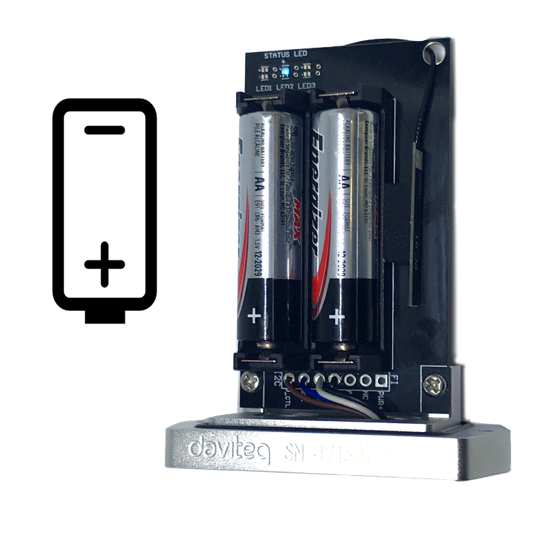
There are 3 configuration menus: tx_repeat, downlink_flag, radio configuration.
We use the button to enter the menus as follows:
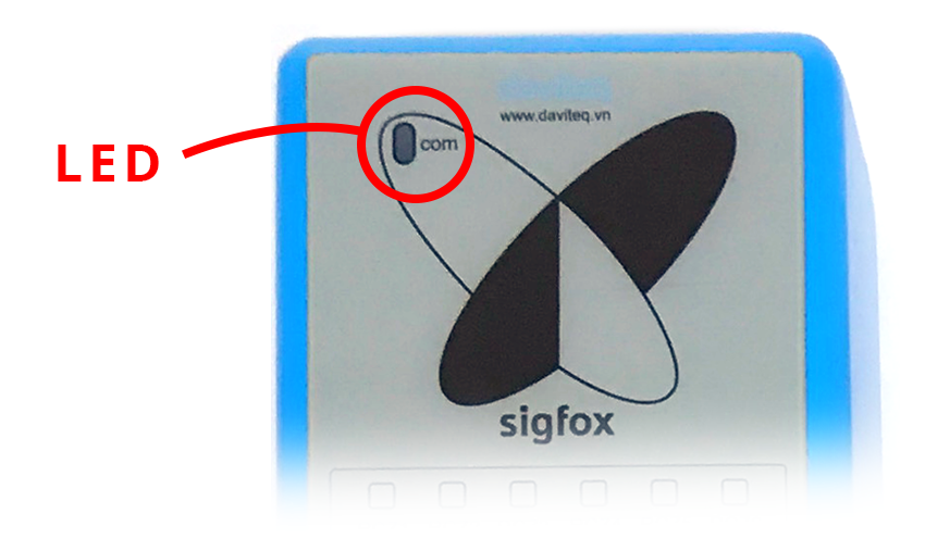
Press and hold the button 2s -> When the Red LED is on, it means entering the tx_repeat configuration menu. Then
release to configure it.
Press to configure. After pressing if the Red LED flashes once, tx_repeat = 0 (send 1 time). After pressing if the Red
LED blinks twice, it is tx_repeat = 1 (send 3 times).
Press and hold the button 5s -> When the Green LED is on, it means entering the downlink_flag configuration
menu. Then release to configure it.
Press to configure. After pressing if the Green LED flashes once, it is downlink_flag = 0 (downlink is not allowed).
After pressing if the Red LED blinks twice, it is downlink_flag = 1 (downlink is allowed).
Press and hold the button 10s -> Blue LED is on, it means entering the Radio Configuration menu. Then release to
configure it.
Press to configure. After pressing if the Blue LED blinks once, it is Radio Configuration = 1. After pressing if the
Blue LED flashes twice, it is Radio Configuration = 2. After pressing if the Blue LED flashes 4 times, it is Radio
Configuration = 4.
There are 3 ways to exit the menu:
Press and hold for 3s, the LED turns off to exit the menu;
Wait 30 seconds, then exit the menu;
Take out the battery, it all starts over (outside the menu)).
The RF transmit power will be automatically set as the max value as allowed by the Zone.
Sigfox Radio Configuration (RC) defines the radio parameters in which the device shall operate: Sigfox operating
frequencies, output power, spectrum access mechanism, throughput, coexistence with other radio technologies, etc.
Each radio configuration includes 4 uplink classes: 0u, 1u, 2u, and 3u.
the push button can only be used for the first 60 seconds after powering up.
5.2.1 Menu configuration
5.2.1.1 tx_repeat
5.2.1.1 downlink_flag
5.2.1.1 radio configuration
5.2.2 Exit the menu:
5.3 RC technical details
The Sigfox network globally works within the ranges from 862 to 928 MHz. But not all RCs require such a wide range of
operation.
RC1
RC2
RC4
868.130
902.200
920.800
869.525
905.200
922.300
100
600
600
600
600
600
16
24
24
Duty cycle
1% *
Frequency
hopping **
Frequency
hopping **
* Duty cycle is 1% of the time per hour (36 seconds). For an 8 to 12 bytes payload, this means 6 messages per hour,
140 per day.
** Frequency hopping: The device broadcasts each message 3 times on 3 different frequencies. Maximum On time
400 ms per channel. No new emission before 20 s.
*** Listen Before Talk: Devices must verify that the Sigfox-operated 200 kHz channel is free of any signal stronger
than −80 dBm before transmitting.
Sigfox’s high limit EIRP recommendation is included in each column although regulations sometimes allow for more
radiated power than the Sigfox recommendation.
Sigfox’s recommendation is set to comply with the Sigfox technological approach of:
Low current consumption
Balanced link budget between uplink and downlink communication
Step 1: Log in to the sigfox backend website
Step 2: Click on Device
5.4 Add a device to the Backend Sigfox
Step 3: Click New → Select a group
Step 4: Fill in the required information
Click on the text as shown below
Check the box as shown below to register as a prototype
Note: Some of our products may not have end product certification in time, to add the product to Backend
Sigfox please follow the steps below.
When the time interval is reached, for example 30 minutes, the Sigfox node will wake up and switch ON the power
supply to supply the energy to vibration sensor module to start the measurement. Depends on the type and
characteristic of external sensor, the sensor will take a certain time to finish the measurement.
With vibration sensor, here are the 8 measurement values:
Acceleration Peak (m/s2)
Acceleration RMS (m/s2)
Velocity Peak (mm/s)
Velocity RMS (mm/s)
Displacement Peak-Peak (um)
Displacement RMS (um)
Base vibration frequency (Hz)
Temperature (oC)
Because the Payload of Sigfox sensor is limited by 12 bytes, we use the first 02 bytes for Sensor information and
status, the rest 10 bytes will store measurement value. With above 8 measurement values, we have to device it into 03
datagrams. Each datagram will be sent each time.
Values to be sent in Datagram 1:
Velocity RMS (mm/s)
Acceleration Peak (mm/s)
Frequency (Hz)
Values to be sent in Datagram 2:
Velocity Peak (mm/s)
Acceleration RMS (m/s2)
Temperature (oC) (Real Temperature value = Temperature value / 10)
Values to be sent in Datagram 3:
5.5 Measurement principle of Sigfox Vibration
Sensor
Displacement Peak-Peak (um)
Displacement RMS (um)
Frequency (Hz)
The following is the format of payload data will be sent to Sigfox server.
Sensor type (1 byte)
Status + Datagram (1
byte)
Parameter 1 (4 bytes)
Parameter 2 (4 bytes)
Parameter 2 (2 bytes)
Meaning of Data in the Payload
Data
Size
Bit
Format
Meaning
Sensor type
1 byte
all
Uint8
Sensor type:
0x10 means
Sigfox V1A
0xFF means no
sensor.
Status: battery level
2 bits
Bit 7 and 6
Battery capacity in
04 levels
11: battery
level 4 (99%)
10: battery
level 3 (60%)
01: battery
level 2 (30%)
00: battery
level 1 (10%)
Status: error
2 bits
Bit 5 and 4
Node status
01: error
00: no error
Datagram
4 bits
Bit 3 to 0
Datagram
000 : Datagram 1
001 : Datagram 2
010 : Datagram 3
Parameter 1
4 bytes
all
Float
Datagram 1 :
Velocity RMS (mm/s)
Datagram 2 :
Velocity Peak (mm/s)
Datagram 3 :
Displacement Peak-
Peak (um)
Parameter 2
4 bytes
all
Float
Datagram 1 :
Acceleration Peak
(mm/s)
Datagram 2 :
Acceleration RMS
(m/s2)
Datagram 3 :
Displacement RMS
(um)
User can configure the Sigfox node to send any number of datagram, but minimum is Datagram 1. The
configuration can be done offline via cable & software OR via downlink.
5.6 Payload Data
5.6.1 Payload for uplink 12 bytes
Parameter 3
2 bytes
all
Datagram 1 : uint16;
Datagram 2 : int16;
Datagram 3 : uint16
Datagram 1 :
Frequency (Hz)
Datagram 2 :
Temperature (oC)
Real Temperature
value = Temperature
value / 10
Datagram 3 :
Frequency (Hz)
User can set the down link data in Sigfox back-end system in advance, whenever the Sigfox node connected to base
stations and with downlink waiting is enable at that time (one time in 6 hours), the downlink data will be loaded to
Sigfox node.
The downlink data can be any configuration parameter.
Downlink payload format:
Prm_adr (1 byte)
Prm_len (1 byte)
Prm_value (6 bytes)
Examples of Downlink data to configure the Sigfox node:
Prm_name
Prm_adr
Prm_len
Comment
cycle_send_data
0x12
0x04
to configure the interval time of
data sending, in seconds.
Enb_datagram
0x44
0x02
to configure which datagram to be
sent.
Explain for Enb_datagram:
bit 0 = 1: enable datagram 1
bit 0 = 0: disable datagram 1
bit 1 = 1: enable datagram 2
bit 1 = 0: disable datagram 2
bit 2 = 1: enable datagram 3
bit 2 = 0: disable datagram 3
Some examples of Enb_datagram:
Enb_datagram = 0x0000 ==> Only datagram 1 will be sent.
Enb_datagram = 0x07 = 0b00000111 ==> Enable 3 datagrams
At 1st cycle_send_data , Sigfox V1A will send datagram 1
At 2nd cycle_send_data , Sigfox V1A will send datagram 2
At 3rd cycle_send_data , Sigfox V1A will send datagram 3
At 4th cycle_send_data , Sigfox V1A will send datagram 1 and so on.
Enb_datagram = 0x05 = 0b00000101 ==> Enable datagram 1 and 3, disable datagram 2
At 1st cycle_send_data , Sigfox V1A will send datagram 1
At 2nd cycle_send_data , Sigfox V1A will send datagram 3
At 3rd cycle_send_data , Sigfox V1A will send datagram 1
At 4th cycle_send_data , Sigfox V1A will send datagram 3 and so on.
Using the configuration cable to connect to the sensor as below picture.
5.6.2 Payload for Downlink, length is 8 bytes.
The Sigfox node is only able to receive max 04 downlinks a day, each downlink will be waiting in every 06 hours.
Please pay attention when send downlink data. If there was a mistake in sending wrong data, it would
cause the Sigfox node not working properly and user need to configure it by offline cable!!!
6. Offline configuration
During connection with Modbus configuration tool, the Sigfox node will send all data in realtime: Battery, Battery level,
Vref, Button status, reed switch status, PCB temperature, Measured value, alarm status.
Step to configure & check data:
Step 1: Install the Modbus Configurator Software in the link below
https://filerun.daviteq.com/wl/?id=qK0PGNbY1g1fuxTqbFW9SXtEvCw7bpc6
Step 2: Plug the configuration cable to Computer via USB port;
Step 3: Open the housing;
Serial port configuration on computer: 9600 baud, None parity, 1 stop bit.
Reading data by Function 3.
Writing data by Function 16.
NOTE:
The Modbus configuration can be done in the first 60s after power up the Sigfox node. After 60s, if user can not
finish the configuration, user need to reset the power of Sigfox node again, by removing battery in at least 15s.
How to use the Modbus configuration software
Step 4: Plug the connector to the configuration port;
Step 5: Import the configuration file by importing the csv file: Go to MENU: FILE / Import New / => select the file
with name CONFIGURATION TEMPLATE FILE FOR SIGFOX.csv (in the link below). Then click Connect;
CONFIGURATION TEMPLATE FILE FOR SIGFOX WSSFC-V1A.csv
Modbus
Register
(Decimal)
Modbus
Register
(Hex)
Function
Code
# of
Registers
Description
Range
Default
Format
Property
Comment
0
0
3
2
device info
string
Read
Product
name
2
2
3
4
firmware
version
string
Read
6
6
3
2
hardware
version
string
Read
8
8
3
2
device ID
hex
Read
Product ID
10
A
3
4
device PAC
hex
Read
Product PAC
14
E
3
1
sen_type
1-255
uint16
Read
Sensor or
Input Type
15
F
3
1
batt level
0-3
uint16
Read
Battery
level
16
10
3
1
err_status
0-1
uint16
Read
Sensor
error code
23
17
3
1
batt %
10%, 30%,
60%, 99%
uint16
Read
Battery %
24
18
3
2
batt volt
0-3.67 vdc
float
Read
Battery
Voltage
26
1A
3
2
temp
oC
float
Read
RF module
temperature
28
1C
3
1
vref
0-3.67 vdc
uint16
Read
Vref of RF
Module
29
1D
3
1
btn1 status
0-1
uint16
Read
Button
status, 0:
released, 1:
pressed
30
1E
3
1
btn2 status
0-1
uint16
Read
Reedswitch
status, 0:
opened, 1:
closed
Here is the table of Data will be read by Modbus tool
Here is the table for Configuration:
Modbus
Register
(Decimal)
Modbus
Register
(Hex)
Function
Code
(Read)
Function
Code
(Write)
# of
Registers
Description
Range
Default
Format
Property
Comment
270
10E
3
16
1
Radio
Configuration
1-6
4
uint16
Read/
Write
RC zones
selection
1, 2 ,4 is
RCZ1,
RCZ2,
RCZ4
271
10F
3
16
1
tx_power
20
int16
Read/
Write
RF Tx
power
272
110
3
16
1
tx_repeat
0-1
1
uint16
Read/
Write
Number of
repeat, 0:
1 time, 1:
3 repeats
273
111
3
16
1
downlink_flag
0-1
0
uint16
Read/
Write
1: enable
Downlink,
0: disable
Downlink
(Fw v1.0
hasn't got
Downlink
function)
274
112
3
16
2
cycle_send_data
900
uint32
Read/
Write
Data
sending
cycle, in
seconds
278
116
3
16
1
alarm_limit
44
uint16
Read/
Write
Limit
number of
alarm
sending in
24h
280
118
3
16
2
sensor1:
sampling_rate
120
uint32
Read/
Write
Sensor/Input
1
sampling
rate, in
seconds
282
11A
3
16
2
sensor1:
calc_time
100
uint32
Read/
Write
Measurement
time of
sensor/input
1, in ms
324
144
3
16
1
enb_datagram
0x0001
hex
Read/
Write
bit 0 = 1:
enb
datagram
1
bit 0 = 0:
dis
datagram
1
bit 1 = 1:
enb
datagram
2
bit 1 = 0:
dis
datagram
2
bit 2 = 1:
enb
datagram
3
bit 2 = 0:
dis
datagram
3
enb_datagram
= 0x0000:
emb
datagram
1
7. Installation
To maximize the distance of transmission, the ideal condition is Line-of-sight (LOS) between the Sigfox sensor and
Base station. In real life, there may be no LOS condition. However, the Sigfox sensor still communicate with Base
station, but the distance will be reduced significantly.
7.1 Locate the good place for Radio signal
ATTENTION:
DO NOT install the Sigfox sensor or its antenna inside a completed metallic box or housing, because RF signal
can not pass through metallic wall. The housing is made from Non-metallic materials like plastic, glass, wood,
leather, concrete, cement…is acceptable.
7.2 Process mounting
WARNING:
The sensor should be mounted on an oil-free and grease-free surface as close to the source of
vibration as possible.
For best results, the sensor should be mounted via a drill hole and have an M6x1.0 threaded hole
(an adapter can be used) attached directly to the housing.
Please make sure that the operating ambient temperature is within the specification of sensor.
Prepare the professional tools for installation. The inappropriate tools may cause damage to the
sensor.
DANGER: Do not twist the upper part of sensor, only screwing the sensor by using the HEX wrench with the
lower HEX part of sensor.
Steps for battery installation:
Step 1: Using L hex key to unscrew M4 screws at the side of the housing and carefully pull out the top plastic housing
in the vertical direction
7.3 Battery installation
Step 2: Insert 02 x AA 1.5VDC battery, please take note the poles of the battery
Step 3: Insert the top plastic housing and locking by L hex key
ATTENTION:
REVERSED POLARITY OF BATTERIES IN 10 SECONDS CAN DAMAGE THE SENSOR CIRCUIT!!!
ATTENTION:
When reinstalling the cover, pay attention to put the PCB edge into the middle slot of the box inside as shown
below)
No.
Phenomena
Reason
Solutions
1
Node does not send RF to base
station periodically, LED does not
blink
No power supply or battery
ran out
Configuration sending
cycle is incorrect
Check that the battery is
empty or not installed
correctly
Check the power supply
Check the send cycle
configuration
2
Node does not send RF to base
station according to the alarm,
LED does not blink
The alarm configuration is
incorrect
Running out of the number
of alarms set for the day
Check alarm configuration
Check the configuration for
the maximum number of
alarms per day
3
Node does not send RF to base
station when activated by the
magnetic switch, LED does not
blink
Magnetic switch has
malfunctioned
Or place the Magnet key
not right position
Locate the correct position
for magnet key
Read the status of the
magnetic switch via
modbus (when powering or
attaching the battery) to
see if the magnetic switch
is working.
4
Node has blinked LED when
sending RF but the base station
cannot received
Out of the number of RF
packages of uplink per day
(140 packages / day)
Check on the base station
whether the event
message exceeds the
number of RF packets
5
Node has sent RF but the LED
does not blink
LED malfunction
Contact manufacturer
8. Troubleshooting
  • Page 1 1
  • Page 2 2
  • Page 3 3
  • Page 4 4
  • Page 5 5
  • Page 6 6
  • Page 7 7
  • Page 8 8
  • Page 9 9
  • Page 10 10
  • Page 11 11
  • Page 12 12
  • Page 13 13
  • Page 14 14
  • Page 15 15
  • Page 16 16
  • Page 17 17
  • Page 18 18
  • Page 19 19
  • Page 20 20
  • Page 21 21

daviteq WSSFC-V1A User guide

Type
User guide

The daviteq WSSFC-V1A is a Sigfox-enabled vibration sensor designed for condition monitoring and preventive maintenance applications, featuring a cost-effective design and single-axis vibration measurement capabilities. With its hermetically sealed piezo-ceramic crystal and low-power electronics, it offers reliable and stable output for long-term monitoring.

The device excels in machine health monitoring, providing superior resolution, dynamic range, and bandwidth compared to MEMS devices. It combines vibration measurement with temperature sensing, allowing users to monitor both vibration levels and temperature at the mounting point.

Ask a question and I''ll find the answer in the document

Finding information in a document is now easier with AI