
Introduction
This document provides detailed hardware information on the X-NUCLEO-53L5A1 expansion board. This expansion board is
compatible with the STM32 Nucleo family and the Arduino™ electronic boards. It is designed around the VL53L5CX multi-zone
ranging sensor and is based on the ST patented FlightSense technology.
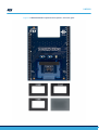
To allow the user to validate the VL53L5CX in an environment as close as possible to its final application, the
X‑NUCLEO-53L5A1 expansion board is delivered with a holder in which three different height spacers of 0.25 mm, 0.5 mm, and
1 mm can be fitted with the cover glass above the spacer. The height spacers are used to simulate different air gap distances
between the VL53L5CX sensor and the cover glass.
Getting started with X-NUCLEO-53L5A1 Time-of-Flight 8x8 multi-zone ranging
sensor with wide FoV based on the VL53L5CX for STM32 Nucleo
UM2889
User manual
UM2889 - Rev 1 - September 2021
For further information contact your local STMicroelectronics sales office.
www.st.com

Figure 1. X-NUCLEO-53L5A1 expansion board, spacers, and cover glass
UM2889
UM2889 - Rev 1 page 2/12

1Overview
The X-NUCLEO-53L5A1 expansion board features the VL53L5CX multi-zone ranging sensor, based on ST’s
FlightSense, Time-of-Flight (ToF) technology.
It is compatible with the STM32 Nucleo development board family, and with the Arduino UNO R3 connector
layout.
Several ST expansion boards can be stacked through the Arduino connectors, which allows, for example, the
development of VL53L5CX applications with Bluetooth or Wi-Fi interfaces.
The X-NUCLEO-53L5A1 expansion board is delivered with:
• Three spacers of 0.25 mm, 0.5 mm, and 1 mm height, used to simulate different air gaps between the
VL53L5CX and the cover glass.
• A cover glass to simulate the integration of the VL53L5CX into the customer’s final product.
• Two 9-pin connectors to enable the customer to connect the two breakout boards onto the
X‑NUCLEO-53L5A1 expansion board.
Note: The VL53L5CX is delivered with a liner to prevent potential foreign material from penetrating inside the module
holes during the assembly process. This liner must be removed at the latest possible step during final assembly,
before module calibration.
Table 1. Ordering information
Order code Description
X-NUCLEO-53L5A1 STM32 Nucleo expansion board - spacers and glass
UM2889
Overview
UM2889 - Rev 1 page 3/12

2Document references
Table 2. Document references
Description DocID
VL53L5CX datasheet DS13754
X-NUCLEO-53L5A1 data brief DB4505
P-NUCLEO-53L5A1 data brief DB4509
X-CUBE-TOF1 data brief DB4449
VL53L5CX-SATEL data brief DB4506
UM2889
Document references
UM2889 - Rev 1 page 4/12

3X-NUCLEO-53L5A1 expansion board
This section describes the X-NUCLEO-53L5A1 expansion board features and provides useful information for
understanding the electrical characteristics.
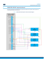
Figure 2. X-NUCLEO-53L5A1 expansion board schematic diagram
UM2889
X-NUCLEO-53L5A1 expansion board
UM2889 - Rev 1 page 5/12

3.1 Description
The board allows the user to test the VL53L5CX functionality, to program it and to understand how to develop an
application using the VL53L5CX. It integrates:
• 3.3 V regulator to supply the VL53L5CX
• Level translators to adapt the I/O level to the main board of the microcontroller
• Arduino UNO R3 connectors
• Optional VL53L5CX breakout board connectors
• Solder drops to allow different configurations of the expansion board
It is fundamental to program a microcontroller to control the VL53L5CX through the I2C bus. The application
software and an example of the C-ANSI source code are available on www.st.com.
The X-NUCLEO-53L5A1 expansion board and STM32 Nucleo development board are connected through the
Arduino UNO R3 connectors CN5, CN6, CN8, and CN9 as shown in Figure 2. X-NUCLEO-53L5A1 expansion
board schematic diagram.
The X-NUCLEO-53L5A1 must be plugged onto the STM32 Nucleo development board through the Arduino UNO
R3 connectors.
3.2 Electrical schematic
The electrical schematics can be downloaded at www.st.com, in the "CAD Resources" section of the
X‑NUCLEO-53L5A1.
3.3 List of materials
The list of material can be downloaded at www.st.com, in the "CAD Resources" section of the
X‑NUCLEO-53L5A1.
UM2889
Description
UM2889 - Rev 1 page 6/12

4VL53L5CX breakout board
The VL53L5CX breakout boards are not present in the X-NUCLEO-53L5A1 package. They can be purchased by
pack of two PCB under the reference VL53L5CX-SATEL.
The VL53L5CX breakout boards are supplied at 3.3 V by the regulator present on the X-NUCLEO-53L5A1
expansion board.
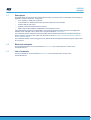
For 3.3 V supply applications, the breakout boards can be broken along the red line as shown in the figure below,
to use the “mini PCB”. This set up is easier to integrate into a customer device due to its small size.
Figure 3. VL53L5CX breakout board layout
The VL53L5CX breakout boards can be directly plugged onto the VL53L5CX expansion board through two 9-pin
connectors, or they can be connected to the board through flying wires (see figure below).
UM2889
VL53L5CX breakout board
UM2889 - Rev 1 page 7/12

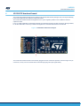
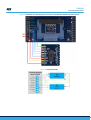
Figure 4. VL53L5CX mini PCB flying wire connection to X-NUCLEO-53L5A1 expansion board
Figure 5. VL53L5CX-SATEL
UM2889
VL53L5CX breakout board
UM2889 - Rev 1 page 8/12

5Safety considerations
5.1 Electrostatic precaution
The user should exercise electrostatic precautions, including using ground straps when using the X-
NUCLEO-53L5A1 expansion board. Failure to prevent electrostatic discharge could damage the device.
Figure 6. Electrostatic logo
5.2 Laser safety considerations
The VL53L5CX contains a laser emitter and corresponding drive circuitry. The laser output is designed to
remain within Class 1 laser safety limits under all reasonably foreseeable conditions including single faults, in
compliance with the IEC 60825-1:2014 (third edition). The laser output remains within Class 1 limits as long
as STMicroelectronic’s recommended device settings are used and the operating conditions specified in the
datasheet are respected. The laser output power must not be increased by any means and no optics should be
used with the intention of focusing the laser beam.
Figure 7. Class 1 laser product label
UM2889
Safety considerations
UM2889 - Rev 1 page 9/12

Revision history
Table 3. Document revision history
Date Version Changes
16-Sep-2021 1 Initial release
UM2889
UM2889 - Rev 1 page 10/12

Contents
1Overview ..........................................................................3
2Document references ..............................................................4
3X-NUCLEO-53L5A1 expansion board...............................................5
3.1 Description ....................................................................6
3.2 Electrical schematic ............................................................6
3.3 List of materials ................................................................6
4VL53L5CX breakout board .........................................................7
5Safety considerations..............................................................9
5.1 Electrostatic precaution .........................................................9
5.2 Laser safety considerations ......................................................9
Revision history .......................................................................10
UM2889
Contents
UM2889 - Rev 1 page 11/12

IMPORTANT NOTICE – PLEASE READ CAREFULLY
STMicroelectronics NV and its subsidiaries (“ST”) reserve the right to make changes, corrections, enhancements, modifications, and improvements to ST
products and/or to this document at any time without notice. Purchasers should obtain the latest relevant information on ST products before placing orders. ST
products are sold pursuant to ST’s terms and conditions of sale in place at the time of order acknowledgement.
Purchasers are solely responsible for the choice, selection, and use of ST products and ST assumes no liability for application assistance or the design of
Purchasers’ products.
No license, express or implied, to any intellectual property right is granted by ST herein.
Resale of ST products with provisions different from the information set forth herein shall void any warranty granted by ST for such product.
ST and the ST logo are trademarks of ST. For additional information about ST trademarks, please refer to www.st.com/trademarks. All other product or service
names are the property of their respective owners.
Information in this document supersedes and replaces information previously supplied in any prior versions of this document.
© 2021 STMicroelectronics – All rights reserved
UM2889
UM2889 - Rev 1 page 12/12
-
 1
1
-
 2
2
-
 3
3
-
 4
4
-
 5
5
-
 6
6
-
 7
7
-
 8
8
-
 9
9
-
 10
10
-
 11
11
-
 12
12


ST X-NUCLEO-53L5A1 Time-of-Flight 8x8 multi-zone ranging sensor User manual
- Type
- User manual
- This manual is also suitable for
Ask a question and I''ll find the answer in the document
Finding information in a document is now easier with AI
Related papers
-
ST STM32 Nucleo-64 User manual
-
-
-
-
ST VL53L8CX User guide
-
-
-
STMicroelectronics L6208 User manual
-
-
ST 32 Nucleo Multifunctional Expansion Board For Gas Sensors User guide
Other documents
-
STMicroelectronics X-NUCLEO-PLC01A1 User manual
-
-
-
Silicon Labs AMW006-A02 Wi-Fi Shield User guide
-
-
-
 Quectel BC68-TE-B User manual
-
-
-
STMicroelectronics X-NUCLEO-LED12A1 User guide
