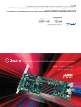
9550SX-12MI

AMCC 9550SX-12MI User manual

  • Hello! I am an AI chatbot trained to assist you with the AMCC 9550SX-12MI User manual. I’ve already reviewed the document and can help you find the information you need or explain it in simple terms. Just ask your questions, and providing more details will help me assist you more effectively!
3ware
®
SATA RAID Controller
Supports the 9550SX Series
PN 720-0124-03
January 2006
Quick Install Guide
Copyright
©2004-2006 Applied Micro Circuits Corporation (AMCC). All
rights reserved. No part of this publication may be reproduced,
stored in a retrieval system, or transmitted in any form by any
means, electronic, mechanical, photocopying, recording or
otherwise, without the proper written consent of AMCC, 215
Moffett Park Drive, Sunnyvale, CA 94089.
Trademarks
3ware, Escalade, and 3DM are all registered trademarks of AMCC.
The 3ware logo, 3BM, StorSwitch, TwinStor, and R5 Fusion are all
trademarks of AMCC. All other trademarks herein are property of
their respective owners.
Disclaimer
While every attempt is made to make this document as accurate as
possible, AMCC assumes no responsibility for errors or omissions
in this document, nor does AMCC make any commitment to update
the information contained herein.
www.3ware.com iii
Chapter 1. Installing an AMCC 3ware 9550SX RAID Controller 1
Before You Begin. . . . . . . . . . . . . . . . . . . . . . . . . . . . . . . . . . . . . . . . . . . . 1
Contents of Package . . . . . . . . . . . . . . . . . . . . . . . . . . . . . . . . . . . . . 1
Other Documentation . . . . . . . . . . . . . . . . . . . . . . . . . . . . . . . . . . . . . 2
Installation Considerations . . . . . . . . . . . . . . . . . . . . . . . . . . . . . . . . . 2
What You Need: Tools and Equipment. . . . . . . . . . . . . . . . . . . . . . . . 4
Safety Factors . . . . . . . . . . . . . . . . . . . . . . . . . . . . . . . . . . . . . . . . . . . . . . 4
Personal Safety . . . . . . . . . . . . . . . . . . . . . . . . . . . . . . . . . . . . . . . . . 4
Protecting Equipment and Data . . . . . . . . . . . . . . . . . . . . . . . . . . . . . 5
9550SX RAID Controller Cards . . . . . . . . . . . . . . . . . . . . . . . . . . . . . . . . . 6
9550SX 8-Port with Standard SATA Connectors . . . . . . . . . . . . . . . . 6
9550SX 4-Port with Standard SATA Connectors . . . . . . . . . . . . . . . . 7
9550SX 12-Port with Standard SATA Connectors . . . . . . . . . . . . . . . 7
9550SX 12-Port with Multilane Internal SATA Connectors. . . . . . . . . 8
9550SX 16-Port with Multilane Internal SATA Connectors. . . . . . . . . 8
Installing a Serial ATA RAID Controller . . . . . . . . . . . . . . . . . . . . . . . . . . . 9
To connect SATA cables to the controller. . . . . . . . . . . . . . . . . . . . . . 9
To install the controller in the computer . . . . . . . . . . . . . . . . . . . . . . 10
To connect the SATA cables to the drives . . . . . . . . . . . . . . . . . . . . 12
Installing a 9550SX RAID Controller with Multilane Internal Connectors. 13
9550SX-12MI . . . . . . . . . . . . . . . . . . . . . . . . . . . . . . . . . . . . . . . . . . 13
9550SX-16ML. . . . . . . . . . . . . . . . . . . . . . . . . . . . . . . . . . . . . . . . . . 14
To connect the multilane cables and install the controller in the
computer . . . . . . . . . . . . . . . . . . . . . . . . . . . . . . . . . . . . . . . . . . 15
To install the drives. . . . . . . . . . . . . . . . . . . . . . . . . . . . . . . . . . . . . . 16
Connecting Drive Activity LED Indicators . . . . . . . . . . . . . . . . . . . . . . . . 17
Finishing Up. . . . . . . . . . . . . . . . . . . . . . . . . . . . . . . . . . . . . . . . . . . . . . . 21
Check Installation and Close the Case. . . . . . . . . . . . . . . . . . . . . . . 21
Configure your RAID Arrays. . . . . . . . . . . . . . . . . . . . . . . . . . . . . . . 21
Chapter 2. Installing the Battery Backup Unit . . . . . . . . . . . . 23
Tools and equipment required . . . . . . . . . . . . . . . . . . . . . . . . . . . . . . . . . 24
Installation Overview . . . . . . . . . . . . . . . . . . . . . . . . . . . . . . . . . . . . . . . . 24
Installation Instructions . . . . . . . . . . . . . . . . . . . . . . . . . . . . . . . . . . . . . . 26
Replacing the Battery . . . . . . . . . . . . . . . . . . . . . . . . . . . . . . . . . . . . . . . 32
Table of Contents
iv 3ware 9550SX Serial ATA RAID Controller Quick Install Guide
Appendix: Technical Support . . . . . . . . . . . . . . . . . . . . . . . . . .35
Sales and ordering information . . . . . . . . . . . . . . . . . . . . . . . . . . . . . . . . 35
Feedback on this manual . . . . . . . . . . . . . . . . . . . . . . . . . . . . . . . . . . . . 35
www.3ware.com 1
Chapter 1. Installing an
AMCC 3ware 9550SX
RAID Controller
This document describes the physical installation of the AMCC
3ware 9550SX RAID controllers. It contains the following topics:
“Before You Begin” provides important information about
things you should consider before starting installation, and
tools and equipment you will need.
“Safety Factors” describes important precautions for your
personal safety and to protect your equipment and data. Be sure
to read this section.
“Installing a Serial ATA RAID Controller” and “Installing a
9550SX RAID Controller with Multilane
Internal Connectors”
provide step-by-step instructions for
installing a Serial ATA RAID controller.
“Finishing Up” describes the final steps required when
installing a serial controller.
Before You Begin
Contents of Package
3ware 9550SX RAID controller
SATA interface cables, one for each port on the controller
Note: With the exception of the 9550SX-16ML RAID
controller, which ships with a multilane break-out cable (SFF-
8087), multilane controllers (such as the 9550SX-12MI,
9500S-12MI, and 9500S-8MI) do not ship with cables.
Multilane cables are sold separately.
This document, 3ware 9550SX Serial ATA RAID Controller
Quick Install Guide
Chapter 1. Installing an AMCC 3ware 9550SX RAID Controller
2 3ware 9550SX Serial ATA RAID Controller Quick Install Guide
Other Documentation
The following additional documentation is available for your 3ware
9550SX RAID Controller:
In PDF format, on the CD that came with your controller, and
available through the 3ware website:
3ware 9550SX Serial ATA RAID Controller User Guide
3ware 9000 Series Serial ATA RAID Controller CLI Guide
In HTML format:
Online help is available from 3DM 2 (3ware Disk Manager)
Additional support information is available in the 3ware
Knowledgebase, at this website:
http://www.3ware.com/KB
Installation Considerations
Cable Length, Routing Space, and Air Flow
When you are installing multiple drives with a controller, make sure
there is adequate space in the chassis for the required cables. It is
important that the cables do not obstruct the air flow or prevent
proper ventilation of the system.
Selecting the Slot in Which to Install the Controller
Consider these factors when deciding on the slot in which to insert
the controller:
Cable routing may be easier if you install the 3ware RAID
controller next to an open slot.
The amount of clearance you need will depend on the number
of drives you will be connecting to the controller.
Before You Begin
www.3ware.com 3
While the 3ware 9550SX RAID controller can be installed in
both 64-bit PCI and PCI-X slots, not all slots give equal
performance.
The 3ware 9550SX controller performs best when installed in a
PCI-X 133MHz 64-bit slot. However, it can also operate at
66MHz or 100MHz.
Whether to Use the LED Status Connector
3ware RAID controllers include two types of LED status
connectors:
Overall indicator, which lights when any drive is active.
Individual LED indicators, for each drive. (Not supported on
chassis that have a common ground.)
If you are building a system from scratch, you may want to consider
using a chassis or drive carrier that is compatible with the 3ware
RAID controller activity LEDs, such as the AMCC RDC-400-
SATA drive carrier, available through AMCC. Please check the
3ware web site (
www.3ware.com) for chassis and drive carrier
compatibility list.
For more information, see “Connecting Drive Activity LED
Indicators” on page 17.
Most chassis have a single drive activity cable that you can connect
to the overall activity indicator on the 3ware 9550SX controller. For
the location of the overall drive activity connector, see the figure for
the appropriate controller in the installation sections starting on
page 18, and refer to Table 1, “LED Indicator Pin Positions,” on
page 20.
Note: If you are using a chassis that includes a Chassis
Control Unit (CCU), follow the instructions that came
with the chassis to connect the I
2
C cable from the CCU
to the I
2
C connector on the 9550SX.
Chapter 1. Installing an AMCC 3ware 9550SX RAID Controller
4 3ware 9550SX Serial ATA RAID Controller Quick Install Guide
Drive Installation Considerations
Selecting an enclosure. If you are planning to use RAID 1, 5,
10, or 50, you may want to consider installing drives into hot-
swappable enclosures, so that they can be easily removed in the
event of a drive failure.
When to install the drives. If the drives are not already
installed in your computer, you can choose to install them
either before or after connecting the SATA cables to them.
What You Need: Tools and Equipment
Tools Required
You will need the following tools during installation:
An ESD grounding strap or mat
Standard hand tools to open your system’s case and install the
3ware RAID controller into an available PCI expansion slot.
Often a philip screen driver is all that is required.
Safety Factors
Be sure to follow the guidelines presented on the next few pages to
insure your own safety, and that of your equipment.
Personal Safety
Warning! High voltages may be found inside computer
equipment.
Before installing any of the hardware in this package or
removing the protective covers of any computer
equipment, turn off power switches and disconnect
power cords. Do not reconnect the power cords until you
have replaced the covers.
Safety Factors
www.3ware.com 5
Protecting Equipment and Data
Backing Up Your Data
Back up your data! Creating or deleting disk arrays
destroys existing files on the member drives. If your drives
contain valuable data, back them up and save the data
elsewhere before attaching the drives to the controller.
ESD (Electrostatic Discharge) Precautions
To avoid damaging computer components and accessories when
installing or removing the 3ware RAID controller, follow standard
electrostatic discharge (ESD) precautions:
When your computer case is open and its internal parts are
exposed, do not touch any internal part unnecessarily.
Always wear a grounded strap or work on an ESD-protective
mat.
Do not remove the 3ware RAID controller from its protective
bag until you are properly grounded.
Handle the 3ware RAID controller by its edges or by the black
rail and metal bracket at its two ends.
Do not touch any pin, contact, lead or component on the 3ware
RAID controller.
Things to Watch Out For
Be careful when installing the 3ware RAID controller into your
system. Excessive force can damage the board or your system.
Be sure the board is aligned with its slot on the motherboard
before installing. Do not flex the board excessively.
SATA cable connectors must be mated carefully with the
connectors in the controller.The connectors provided are keyed
to prevent you from inserting them upside-down.
SATA cables are fragile and must not be crimped or pinched.
Ensure that they do not impede the flow of cooling air from
fans or heat sinks in the system case.
Chapter 1. Installing an AMCC 3ware 9550SX RAID Controller
6 3ware 9550SX Serial ATA RAID Controller Quick Install Guide
9550SX RAID Controller Cards
Serial ATA ports are usually double-stacked connectors. Odd-
numbered ports are usually located below even-numbered ports. On
the 8-port controller shown below, ports 6 and 7 are both on top.
9550SX 8-Port with Standard SATA Connectors
Note: For details about LED connectors, see page 17.
Figure 1. 8-Port 3ware 9550SX-8LP Serial ATA RAID Controller
Ports:
4 and 5
2 and 3
0 and 1
Odd-numbered ports 1 through 5 are located
below even-numbered ports 0 through 4.
I
2
C connector
Ports 6 and 7 (top only)
BBU connector and hole for post
Slots for battery
holder
Ports: 0 1 2 3 4 5 7 6
9550SX RAID Controller Cards
www.3ware.com 7
9550SX 4-Port with Standard SATA Connectors
Figure 2. 4-Port 3ware 9550SX-4LP Serial ATA RAID Controller
9550SX 12-Port with Standard SATA Connectors
Figure 3. 12-Port 3ware 9550SX-12 Serial ATA RAID Controller
Ports:
2 and 3
0 and 1
Odd-numbered ports 1 and 3 are located
below even-numbered ports 0 and 2.
I
2
C connector
BBU connector and hole for post
Slots for
battery holder
Ports:
8 and 9
6 and 7
4 and 5
2 and 3
0 and 1
Odd-numbered ports 1 through 11 are located
below even-numbered ports 0 through 10.
I
2
C connector
Ports 10 and 11
BBU connector and hole for post
Holes for battery
holder connection
Chapter 1. Installing an AMCC 3ware 9550SX RAID Controller
8 3ware 9550SX Serial ATA RAID Controller Quick Install Guide
9550SX 12-Port with Multilane Internal SATA
Connectors
Figure 4. 12-Port 3ware 9550SX-12MI Serial ATA RAID Controller
9550SX 16-Port with Multilane Internal SATA
Connectors
Figure 5. 16-Port 3ware 9550SX-16ML Serial ATA RAID Controller
Ports:
8 to 11
4 to 7
0 to 3
M
u
l
t
i
-
l
ane connectors can eac
h
handle up to four drives.
I
2
C connector
BBU connector and hole for post
Holes for battery
holder connection
Ports:
12 to 15
8 to 11
4 to 7
0 to 3
M
u
l
t
i
-
l
ane connectors can eac
h
handle up to four drives.
I
2
C connector
BBU connector and hole for postHoles for battery
Installing a Serial ATA RAID Controller
www.3ware.com 9
Installing a Serial ATA RAID Controller
Note: The illustrations in this section show a
9550SX-8LP. If you have a different model of controller,
the location of the ports will be slightly different, but the
steps are very similar. For location of the ports on all
boards, see the illustrations on page 6 through page 8.
Note: If you have a Battery Backup Unit (BBU), install
it on the controller before proceeding. For details, see
“Chapter 2. Installing the Battery Backup Unit”.
To connect SATA cables to the controller
Note: If you have a multilane controller, turn to page 13.
1 Take out the SATA cables provided with the 3ware SATA
RAID controller.
One edge of each SATA cable connector is keyed so that it can
only be inserted in one direction. This helps to ensure proper
orientation and installation
2 Decide to which port you want to connect the first cable.
Chapter 1. Installing an AMCC 3ware 9550SX RAID Controller
10 3ware 9550SX Serial ATA RAID Controller Quick Install Guide
3 Align the cable connector with the connector on the controller,
matching the slotted key and carefully mate the connectors.
Note: The connectors on the end of the serial
controller and the drive are susceptible to damage
from excessive bending. Be careful not to insert or
remove the SATA cable connector at an angle.
Figure 6. SATA Cables Being Inserted Into Port
4
5 Repeat steps 2 and 3 for each additional SATA cable. (You will
connect one cable for each hard drive you will attach.)
To install the controller in the computer
1 If the computer is running, shut it down. Turn off power to the
computer and disconnect the power cord from the outlet.
2 Make sure you are properly grounded. (For details about safety
precautions, see
page 4.)
3 Open the computer case according to the manufacturers
instructions.
4 Find the PCI or PCI-X slot you want to use for the serial 3ware
RAID controller.
For a discussion of which slot to use, see “Selecting the Slot in
Which to Install the Controller” on page 2.
5 Remove the metal filler bracket for the slot.
Installing a Serial ATA RAID Controller
www.3ware.com 11
Save this screw; it will be used to secure the serial 3ware RAID
controller after you have seated it in the slot.
6 Position the card in the slot so that the contacts will mate with
the grooves in the slot, and all pins make proper contact with
the PCI slot pins when pushed into place.
The 3ware RAID controller is keyed to ensure proper
installation into a full-sized 3.3-volt PCI or PCI-X slot.
Make sure that the contacts will mate with the grooves in the
slot.
7 Press down gently on the edge of the 3ware RAID controller
directly above the slot until it is fully seated.
Figure 7. Inserting Controller Into PCI Slot
Chapter 1. Installing an AMCC 3ware 9550SX RAID Controller
12 3ware 9550SX Serial ATA RAID Controller Quick Install Guide
8 Check that the 3ware RAID controllers metal bracket covers
the hole in the case and secure the bracket with the screw that
was used to secure the filler bracket in step 5.
To connect the SATA cables to the drives
1 If your drives are not already installed in the computer chassis
or hot swap carriers, install them now. Be sure that the drives
are connected to the power supply, either by cable or through
the drive cage.
2 For each drive, select the end of an SATA cable not connected
to the 3ware RAID Controller and plug it into the drive or drive
carrier.
One edge of each SATA cable connector is keyed to ensure
proper installation.
Figure 8. SATA Cable Connecting to Drive
3 (Optional) Connect the drive activity LED connectors. For
details, see the connection details on
“Connecting Drive
Activity LED Indicators” on page 17.
For a discussion of whether to make these connections, see
“Whether to Use the LED Status Connector” on page 3.
4Turn to “Check Installation and Close the Case” on page 21.
Installing a 9550SX RAID Controller with Multilane Internal Connectors
www.3ware.com 13
Installing a 9550SX RAID Controller
with Multilane Internal
Connectors
Models 9550SX-12MI and 9550SX-16ML come with multilane
internal connectors, each of which can handle up to four drives.
These controllers can be installed in an enclosure with a backplane.
The type of cable you need will depend on whether you have a 12-
or 16-port card and the type of enclosure you have.
9550SX-12MI
With a backplane that has the InfiniBand 4x connectors
(SFF-8470), use the InfiniBand 4x cable, which has multilane
connectors on each end (see Figure 9).
Figure 9. Multilane Serial ATA Cable (InfiniBand 4x, SFF-8470)
With a backplane that has individual SATA connectors or
individual serial ATA drives, use the multilane break-out cable,
which has an SFF-8470 multilane connector on one end, and 4
individual SATA connectors on the other end (see Figure 10).
Figure 10. Multilane Serial ATA Break-out Cable (SFF-8470)
Chapter 1. Installing an AMCC 3ware 9550SX RAID Controller
14 3ware 9550SX Serial ATA RAID Controller Quick Install Guide
9550SX-16ML
With a multilane-enabled drive backplane that has the
SFF-8087 mini SAS 4i connectors, use the double-ended 4x
cable, which has multilane connectors on each end (see
Figure 11).
Figure 11. Multilane Cable Serial ATA (SFF-8087)
With a backplane that has individual SATA connectors or
individual serial ATA drives, use the multilane break-out cable,
which has an SFF-8087 multilane connector on one end, and
four individual SATA connectors on the other end (see
Figure 12).
Figure 12. Multi-lane Serial ATA Break-out Cable (SFF-8087)
Installing a 9550SX RAID Controller with Multilane Internal Connectors
www.3ware.com 15
To connect the multilane cables and install the
controller in the computer
Depending on the number of drives you will be connecting, you
will connect one to three multilane cables (for the 12-port card) or
one to four multilane cables (for the 16-port card). Each cable
supports up to four serial ATA ports.
1 Connect each multilane cable to a multilane connector on the
controller.
When the cable is inserted correctly, you will feel it click into
place.
Figure 13. Connecting an InfiniBand Multilane Cable with an
SFF-8470 Connector to the 9550SX-12MI Controller
Figure 14. Connecting a Multilane Cable with an SFF-8087
Connector to the 9550SX-16ML Controller
Chapter 1. Installing an AMCC 3ware 9550SX RAID Controller
16 3ware 9550SX Serial ATA RAID Controller Quick Install Guide
2 Insert the controller into the computer. For details, see “To
install the controller in the computer” on page 10.
3 If your enclosure has a backplane, connect the other end of each
multilane cable to the backplane.
If you are using a standard enclosure, connect each of the
individual SATA connectors to a drive.
To install the drives
1 If your drives are not already installed, install them now, either
by attaching them to the backplane, or by installing them in the
computer chassis.
2 Be sure that the power supply is connected to either the
backplane or the individual drives.
/