Page is loading ...

7:S600
Specification Sheet June 2009
Remote Automation Solutions
Website: www.EmersonProcess.com/Remote
D301151X412
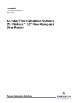
FloBoss™ S600 Flow Manager
The FloBoss S600 Flow Manager is a panel-mount
flow computer designed specifically for
hydrocarbon liquid and gas measurement where
versatility and accuracy matter. The standard
features of the unit make it ideal for fiscal
measurement, custody transfer, batch loading, and
meter proving applications. The unit allows
configuration of multi-stream, multi-station
applications, enabling you to simultaneously meter
liquids and gasses.
The FloBoss S600 Flow Manager is designed for
use either as a stand alone Flow Computer or as a
system component. The base unit is supplied with
a single Input/Output (I/O) board and can be used
for both gas and liquid applications. The I/O
capability of the single I/O board is detailed on
Page 5, but is generally suitable for 2 of 3 streams
and a header. Additional I/O boards can be added
(maximum of 3) to enable a single FloBoss S600
to handle up to 10 streams and up to 2 headers,
with both Gas & Liquid in a single machine. Orifice,
ultrasonic, turbine, positive displacement, Coriolis,
Annubar, Venturi, and V-Cone flow meter types
are all supported.
The Floboss S600 uses distributed processing to
achieve maximum performance. The main CPU
incorporates a hardware floating point processor.
Each additional card also has local processing to
convert inputs and output from engineering units to
field values and vice-versa, as well as running
background tests and PID loops.
FloBoss S600 Flow Manager
All metering calculations are performed using 64-
bit (double) precision floating point numbers for the
highest accuracy. Cumulative totals are stored in
three separate memory locations (Tri-reg format)
for maximum integrity. The user language
Logicalc™ also allows double precision
mathematical functions to be performed on the
database objects.
The reliability of the analog performance of the
FloBoss S600 allows longer intervals between
calibration checks.
The FloBoss S600 Flow Manager offers multiple
communication interfaces:
One or two Ethernet 10baseT ports. An
optional second Ethernet port can be added if
required.
HART communication is facilitated using a 12-
channel HART board, supporting point-to-point
and multi-drop architectures (up to 50
transmitters).
An embedded webserver allows remote
access to the flow computer. Security is
provided by way of user name and password
protection with a detailed event log for audit
purposes. Supports Windows
®
Internet
Explorer
®
version 5 or greater.
Two configurable EIA-232 (RS-232) serial
ports for connection to a printer or RTU.
Three EIA-422/485 (RS-422/RS-485) serial
ports (up to 38400 bps baud) for connection to
intelligent meters, Modbus SCADA data
networks, or a DCS Supervisory System.
One dedicated configuration port for
connection to the Config600 configuration
software.
Use the software interface (Config600 Lite,
Config600 Lite+, or Config600 Pro) to upload and
download configurations. You can also create or
edit configuration files using Config600 Lite+ and
Config600 Pro (refer to the Config600 specification
sheet, 4:C600). Finally, the keypad interface on
the S600/webserver enables you to review or
modify system parameters.
Continued on Page 2

7:S600
Specification Sheet Page 2
Base Unit Specifications
DISPLAY-KEYPAD ENCLOSURE
Graphics Display: LCD 128 x 64 pixel (8 lines of
20 alpha-characters) with LED backlight, using
a Toshiba T6963 LCD controller.
Painted, welded steel outer case with plastic front
panel.
Classification: IP50 from front panel.
Alarm/Status: 3 color LED: green, amber, red.
Dimensions
Keyboard: 29 self-colored silicon rubber keys
with tactile feel.
Case: 84.5 mm W by 270 mm H by 303.8 mm
D (3.327 in. W by 10.63 in. H by 11.94 in. D).
Display Keypad Moulding: 85 mm W by 269
mm H by 28 mm D (3.35 in. W by 10.59 in. H
by 1.10 in. D).
Configuration Port: RJ12 connector for the
Config600 package on the bottom of the front panel
moulding.
Panel Cutout: 66 mm W x 150 mm H (2.6 in.
W by 5.9 in. H) with ±1 mm tolerance.
POWER REQUIREMENTS
Supply Voltage: 20-32 V dc, 24 W nominal, 48 W
maximum.
Pitch Between Cases: 110 mm (4.33 in.)
giving 25 mm (0.98 in.) air gap.
Typical: 18 W with 1 I/O board.
24 W with 2 I/O boards.
36 W with 3 I/O boards.
Max Panel Thickness: 10 mm (0.39 in.).
Weight: 4.3 kg (9.48 lb) approximate with a
single I/O board space configuration.
Protection: 2.5 A anti-surge fuse.
Circuit Boards: Eurocard-compatible, slide in and
out from the rear.
Inrush Current: Thermistor protection providing 6
A at 25ºC.
Access: Allow 300 mm (11.81 in.) clearance
directly behind case for maintenance.
Supply Isolation: Three-way, galvanically
isolated from input to computer, supply and
ground, 50 V.
Operating Temperature: 0°C to 60°C (32°F to
140°F).
Hold-up Period: 4 ms after power fail flag.
Storage Temperature: –40°C to 70°C (–40°F to
158°F).
Maximum Input Ripple: 2 V pk-pk.
Input Power Fail Flag: 17-19 V dc.
Relative Humidity: 90% non-condensing.
Power Outputs: 24 V dc, 500 mA; 15 V dc,
100 mA. 50 V dc isolation. The outputs are
together isolated from the supply voltage and
from the computer.
Safety Classification: For use in a classified safe
electrical area.
EMC: Complies with the following European Union
EMC regulations.
Emissions: EN55022-B.
Immunity: EN61000-4, IEC-EN 61000-6-2.
Continued from Page 1
K factor or Meter Factor linearization. The FloBoss S600 Flow Manager provides the
following functions through the Config600
configuration tool:
Valve monitor/control.
Sampler control.
Stream and station totalization.
Station densitometer.
Batch totalization and correction.
Station gas chromatograph.
3-term PID control.
Forward, reverse and error totals.
Flow balancing.
Comprehensive maintenance mode.
Flow scheduling.
Coriolis meter interface.
Automatic proving sequence.
Ultrasonic meter interface.
Supports Modbus/TCP or Modbus over
Ethernet.

7:S600
Specification Sheet Page 3
CPU and Calculation Specifications
CALCULATIONS CPU CAPABILITY
Processor: 50 MHz.
Gas: AGA 3 (Volume and Mass), AGA 5, AGA 7,
AGA 8, AGA 10, GPA 2172 & 2145, ISO 5167,
ISO 6976, ISO12213 – 2 & 3,
GOST 8.563.1 & 2 (97), GOST 8.586,
GOST 30319, PR 50.2.019, NX 19,
NX 19 Mod, S-GERG, M-GERG,
VDI/VDE 2040, PTZ, Annubar, V-Cone.
Memory: 16 MB DRAM, 2 MB SRAM (battery-
backed), 4 MB Flash.
Real-Time Operating System: Wind River
VxWorks.
Battery Backup (SRAM)
Charging time: 48 hours (20%-80%).
Liquid: API 2540 (Tables 5, 5A, 5B, 5D, 6, 6A,
6B, 6C, 6D, 23, 23A, 23B, 23D, 23E, 24, 24A,
24B, 24C, 24D, 24E, 53, 53A, 53B, 54, 54A,
54B, 54C, 54D, 59A, 59B, 60A, 60B), API 11.1,
API 11.2.1, API 11.2.1M, API 11.2.2,
API 11.2.2M, API 11.2.4, API 12.2.1,
API 12.2.1M, API 12.2.2, API 12.2.2M,
ASTM D1555 & D1555M, GPA TP15, GPA
TP15M, GPA TP16, GPA TP25, GPA TP27,
Steam & Water IAPSW 1967, NPD, Propylene
API 11.3.2.2, Ethylene IUPAC, NIST 1045 &
API 11.3.2.1, Downer, ISO 91/1 (IP2), ISO 91/2
(IP3).
Hold-up Time (without recharge): 3 months at
20°C, 1 month at 40°C.
Battery Life (Typical): 5-7 years.
Battery Backup Hold Time (after battery has
failed its load test): 6 weeks at 20°C.
Form ‘C’ Watchdog Relay
Contact Form: Change-over contacts.
Max Current: 1 A.
Max Voltage: 50 V dc.
Maximum Power: 30 VA.
Control: Released on de-power, or watchdog
restart, or software-controlled.
Solartron/MicroMotion densitometer algorithms,
Sarasota/PEEK densitometer algorithms.
Clock Facilities
Type: Battery-backed calendar clock.
Prover: Compact, uni-directional, bi-directional,
master meter, dual chronometery. Support for
1, 2, or 4 sphere switches. Each S600 can
support up to two provers.
Watchdog Period: 2.5 seconds maximum.
Clock Accuracy
Powered On: 0.5 seconds per day.
Battery Supported: 10 seconds per day.
APPROVALS AND COMPLIANCES
Available with European CE Mark.
MID MI-002 (Gas) & MI-005 (Liquid) of European
Directive 2004/22/EC
OIML R117 & OIML R117-1
EN12405 For EFM devices compliant.
Approved by NMI (Netherlands Measurement
Institute, CMI (Czech Metrology Institute), OMH
(Hungarian National Office of Measure), BRML
(Romania), SDM (France) GOST (Russia) SMU
(Slovak Republic), CSA (Canada), PAC (China),
DMDM (Serbia), INMETRO (Brazil), GOST-K
(Kazakhstan) and OMNL (Algeria).

7:S600
Specification Sheet Page 4
Communication Specifications
RS232 Ports (Ports 3 & 4) COMMUNICATION
Connector: FCC-68 RJ45.
Configuration Port (located on the bottom of the
front panel)
Communication Standard: RS232D.
Signals Supplied: Tx, Rx, RTS, CTS, DTR,
DSR, GND, DCD.
Connector: 6-pin RJ12.
Communication Standard: RS232D.
Baud Rate:300, 600, 1200, 2400, 4800, 9600,
19200, 38400.
Signals Supplied: Tx, Rx, CTS, GND.
Baud Rate: 300, 600, 1200, 2400, 4800, 9600,
19200, 38400.
Format: Software configurable.
Data Protocol: ASCII, MODBUS (ASCII,
RTU).
Format: Config600 Protocol.
Ethernet (Ports 1 & 2)
RS422/RS485 Ports (Ports 5, 6, & 7)
Port 1: Standard.
Connector: standard screw terminals, 3.5 mm
pitch, 13-pin.
Port 2: Optional, with P190 board installed.
Speed: 10 Mbit/second.
Communications: RS422 - point-to-point - 4
wire RS422 – multidrop (RS485 4 wire) - 4
wire RS485 - multimaster - 2 wire.
Media Connectivity: 10baseT, twisted pair
utilizing standard RJ45.
Protocol: Modbus/TCP or Modbus over
Ethernet.
Signals Supplied: Tx+, Tx-, Rx+, Rx-,
common shield.
Baud Rate: 300, 600, 1200, 2400, 4800, 9600,
19200, 38400.
Format: Software controlled on each channel.
Data Protocol: ASCII, MODBUS (ASCII,
RTU).

7:S600
Specification Sheet Page 5
Expansion Boards
The FloBoss S600 is supplied with one P144 I/O board and one P148 Pulse Mezzanine as standard. There
are two additional slots available to accept additional expansion boards, these can be the following:
P144 I/O Board – Provides the S600 with additional analog and digital I/O.
P148 Pulse Mezzanine – Provides pulse input capability. Fits on P144 and P154 boards and does not
use an additional slot.
P154 Prover board – For applications with a prover.
P188 HART board – For applications with HART transmitters.
P190 2nd Ethernet board – Provides a second Ethernet port.
Details of these optional boards are as follows:
P154 PROVER BOARD (continued) P144 I/O BOARD (1 standard, additional boards are
optional)
Digital Outputs
Analog Inputs
Quantity: 12
Quantity: 12
Pulse Inputs-Flow/Turbine (requires Pulse
Mezzanine board)
Analog Outputs
Quantity: 2 dual pulse or 4 single pulse. Quantity: 4
Frequency Density Inputs: Digital Inputs
Quantity: 2 Quantity: 16
Pulse Outputs Digital Outputs
Quantity: 4 Quantity: 12
Raw Pulse Input
Pulse Inputs-Flow/Turbine (requires Pulse
Mezzanine board): 2 dual pulse or 4 single
pulse.
Quantity: 3
Phase Loop Lock Input
Frequency Density Inputs: 3.
Quantity: 2
PRT (RTD) Inputs: 3, 4-wire.
Switch Detect
Pulse Outputs: 5.
Quantity: 4
Raw Pulse Output: 1, Raw pulse output for
proving, 0 to 5 kHz.
P188 HART BOARD (optional)
Supports dual master (primary or secondary), read
only (can not be used to change constants on the
HART board). Does not support burst mode.
P148 PULSE MEZZANINE (1 standard, additional
boards are optional)
Fits on P144 and P154 boards to provide pulse
input capability.
Quantity: 12 Channels. Each channel can be
configured for point-point or multi-drop
communications. In multi-drop mode, each
channel can support up-to 8 transmitters
Quantity: 2 dual pulse or 4 single pulse.
Note: The P148 Pulse Mezzanine board fits on
a P144 or P154 board and does not use an
additional slot.
Max. Number of HART Transmitters: 50.
P190 ETHERNET BOARD (optional)
P154 PROVER BOARD (optional)
Adds a second Ethernet port to the S600. Refer to
the Ethernet section of the Communication
Specifications table for more information.
Compact, uni-directional, bi-directional, master
meter, dual chronometry. Up to 4 sphere switch.
Digital Inputs
Quantity: 32

7:S600
Specification Sheet Page 6
Input Specifications
PULSE INPUTS-FLOW/TURBINE ANALOG INPUTS
Type: 1 to 5 V, 0 to 5 V, 4 to 20 mA, or 0 to 20
mA, opto-isolated. Two groups of 5 single-
ended voltage or current inputs with each
group sharing a common return; channels 11
and 12 are current input only.
Requires Pulse Mezzanine board to be fitted to a
P144 or P154 board.
Type: Dual pulse or single pulse train, opto-
isolated.
Signal Level: ±3.5 V to ±24 V, minimum 5 mA.
Signal Level: 0 to 5.125 V or 0 to 22 mA.
Frequency Range: 0 to 10 kHz.
Scan Rate: All channels can be acquired in less
than 1 second.
Security Monitoring: IP 252/76 (ISO 6551),
level A or B.
Resolution: 24 bits, auto-zero, auto-calibrate.
DIGITAL STATUS INPUTS
Conversion Time: Less than 100 ms per
channel.
Type: 16 opto-isolated inputs, arranged in 4
groups of 4 with common positive connection
to allow simple interface to open collector
outputs.
Series Mode Rejection: >100 dB at 50 Hz and
60 Hz.
Voltage Common Mode Range: ±50 V as a
group relative to computer ground.
Max Input Voltage: 30 V.
Min Input On Voltage: 12 V.
Common Mode Rejection: >100 dB at 50 Hz
and 60 Hz.
Max Input Off Voltage: 3 V.
Input Impedance: 2-2.5 k typical.
Input Impedance: >10 M (voltage mode),
approx 250 (current mode).
Protection: Reverse voltage protection.
Calibration Period: 2 years to 0.005% of
voltage; 5 years to 0.01% of voltage.
PRT (RTD) INPUTS
Type: 4 wire connection using Pt 100
transducers, opto-isolated.
A/D Converter Inputs Voltage Mode
Type of Inputs: Single-ended voltage inputs.
PRT (RTD) Resistance: 100 [Pt 100 to IEC
751/DIN 43760 (Europe 0.00385), IPTS68
(American 0.00392), Calendar-Van Dusen].
Input Range: 0 to 5.2 V.
Accuracy: ±0.005% of FSD at 23°C (73°F).
Excitation Current: 1 mA nominal.
Ambient Temperature Effect: ± 7 ppm/°C (± 4
ppm/°F) from 23°C (73°F) in the range 0 to
45°C (32 to 113°F).
Measuring Range: 60 to 216 (–100°C to
+300°C) (–148°F to +572°F).
A/D Converter Inputs Current Mode
Resolution: 0.01°C (0.018°F).
Type of Inputs: Single-ended current inputs.
Accuracy: –100°C to 200°C (–148°F to 392°F) ±
0.01% –200°C to 300°C (392°F to 572°F) ±
0.02%.
Input Range: 0 to 22 mA.
Accuracy: ± 0.02% of FSD at 23°C (73°F).
PRT (RTD) Cables: Core resistance up to 600 .
Ambient Temperature Effect
Barriers: 9 V, 100 are satisfactory.
± 10 ppm/°C (± 5.5 ppm/°F) from 23°C in the
range 0 to 45°C (32 to 113°F).
Security: Continuous cable/PRT (RTD)
integrity tests for earths/open circuits.
FREQUENCY/DENSITY INPUTS
Type: dc coupled, opto-isolated.
Signal Level: 3 V min pk-pk.
Maximum Input Voltage: 12 V pk-pk.
Current Limit: Internally limited to 3 mA.
Frequency Range: 0 to 10 kHz.
Accuracy of Frequency Measurement: 10
ppm.
Resolution: 5 nanoseconds.

7:S600
Specification Sheet Page 7
Output Specifications
PULSE OUTPUTS ANALOG OUTPUTS
Type: Opto-isolated open-collectors. Type: 4 to 21 mA outputs, opto-isolated.
Frequency Range: 0 to 100 Hz. Resolution: 12 bit minimum.
Max Output Current: 100 mA. Accuracy: ± 0.1% at 23°C (73°F).
Max Output Saturation Voltage: 1.5 V @ 100
mA.
Ambient Temperature Effect: 20 ppm/°C
(11ppm/°F) from 23°C (73°F).
Low Current Saturation Voltage: 600 mV @ 1
mA to suit TTL style input.
Load Loop Resistance: 650 maximum when
powered by local isolated source, 470W 1000W
when powered from +24 V external supply.
Max Output Standoff Voltage: 42 V (limited by
Transorb).
Maximum External Supply: 32 V.
Output Form: Controlled active current sink to
ground return of local floating supply.
RAW PULSE OUTPUTS
Type: Digital ground-referenced open-collector.
Number of Field Connections: 3 terminals per
channel.
Gating: Software controlled.
Max Output Saturation: 1.5 V.
Update Time: 100 ms to within 1%.
Max Output Standoff Voltage: 26 V (limited by
Transorb).
DIGITAL OUTPUTS
Type: 3 groups of 4 with common negative,
opto-isolated.
Max Output Current: 100 mA.
Frequency Range: 0 to 5 kHz.
Frequency Range: 0 to 0.5 Hz.
Minimum On Period: 100 µs (microseconds).
Max Output Saturation Voltage: 1.5 V @ 100
mA.
Use: To bus together several streams to a
common prover computer.
Low current Saturation Voltage: 600 mV @ 1
mA to suit TTL style input, with 4.7 k pull up to
5 V.
Max Output Standoff Voltage: 42 V (limited by
Transorb).
Max Output Current: 100 mA.
Reset/Power on State: All digital outputs – OFF.

7:S600
Specification Sheet Page 8
Bristol, Inc., Bristol Canada, BBI SA de CV and Emerson Process Management Ltd, Remote Automation Solutions division (UK),
are wholly owned subsidiaries of Emerson Electric Co. doing business as Remote Automation Solutions (“RAS”), a division of
Emerson Process Management. FloBoss, ROCLINK, Bristol, Bristol Babcock, ControlWave, TeleFlow and Helicoid are trademarks
of RAS. AMS, PlantWeb and the PlantWeb logo are marks of Emerson Electric Co. The Emerson logo is a trademark and service
mark of the Emerson Electric Co. All other marks are property of their respective owners.
The contents of this publication are presented for informational purposes only. While every effort has been made to ensure
informational accuracy, they are not to be construed as warranties or guarantees, express or implied, regarding the products or
services described herein or their use or applicability. RAS reserves the right to modify or improve the designs or specifications of
such products at any time without notice. All sales are governed by RAS’ terms and conditions which are available upon request.
RAS does not assume responsibility for the selection, use or maintenance of any product. Responsibility for proper selection, use
and maintenance of any RAS product remains solely with the purchaser and end-user.
Emerson Process Management
Remote Automation Solutions
Marshalltown, IA 50158 U.S.A.
Houston, TX 77041 U.S.A.
Pickering, North Yorkshire UK Y018 7JA
© 2002-2009 Remote Automation Solutions, division of Emerson Process Management. All rights reserved.
/