Page is loading ...

L8542907
09/2011 rev 3
SUNNY
UNIONE NAZIONALE COSTRUTTORI
AUTOMATISMI PER CANCELLI, PORTE
SERRANDE ED AFFINI

R A D I O
PP
COM
PED
STOP
PHC
PHO
COM
SHIELD
ANT
P-P
1
2
MF1
MF2
24 Vac/dc
3 4
5 6
7 8 9 10 11 12
13 14 15 16 17 18 19 20
F1
F2
12V
12V
L
24
0
N
+
+
-
-
SCA
a b
c d e f
J4
Close
D20
1
SUNNY
CONTROL UNIT

3
2A 2B
P
LED
R A D I O
B
3
14 15 16 17 18 19 20
SCA
PP
COM
PED
STOP
PHC
PHO
COM
24 Vac/dc
3 4
5 6
7 8 9 10 11 12
13 14 15 16 17 18 19 20
12V
12V
COM
SWO
SWC

8
EC declaration of confirmity
Manufacturer: Automatismi Benincà SpA.
Address: Via Capitello, 45 - 36066 Sandrigo (VI) - Italia
Herewith declares that: battery charge controller for photovoltaic panel CP.BULL8 OMSUNNY.
complies with the following relevant provisions:
EMC guidelines: 89/336/CCE, 93/68/CEE
Low voltage guidelines: 73/23/CEE, 93/68/CEE
Benincà Luigi, Legal responsible.
Sandrigo, 08/07/2010.
WARNINGS
This manual has been especially written to be use by qualified
fitters.
None of the information provide in this manual can be considered
as being of interest for the end users.
Preserve this manual for future needs.
The technician has to furnish all the information related to the step
by step function, the manual and the emergency function of the
operator, and to deliver the manual to the final user.
;
Foresee on the supply net an onnipolar switch or selec-
tor with distance of the contacts equal or superior to 3
mms.
Verify that of the electrical system there is an awry differential
interrupter and overcurrent protection.
Some typologies of installation require the connection of the
shutter to be link at a conductive mass of the ground according
to the regulations in force.
The electrical installation and the operating logic must comply
with the regulations in force.
The leads fed with different voltages must be physically separate,
or they must be suitably insulated with additional insulation of
at least 1 mm.
The leads must be secured with an additional fixture near the
terminals.
During installation, maintenance and repair, interrupt the power
supply before opening the lid to access the electrical parts
Check all the connections again before switching on the po-
wer.
The unused N.C. inputs must be bridged.
The descriptions and the present illustrations in this manual are
not binding. Leaving the essential characteristics of the product
unchanged, the manufacturer reserves himself the right to bring
any change of technical, constructive or commercial character
without undertaking himself to update the present publication.
TECHNICAL DATA
Type of battery
24Vdc 6.5 ÷ 50 Ah, Pb-Lead
Emergency power supply
230/110>> 24 Vac 45 VA minimum Transformer
Type of photovoltaic panel
Vmp: 15 ÷ 40V (load voltage)
Wp: 15 ÷80 W (max. power)
Power supply output)
24VDC
Protection level
IP 55
Operating temperature
-20°C / +70°C
Radio receiver
433.92 MHz, built-in and configurable (rolling-code or fixed+rolling-code)
No. of codes storable in memory
512

9
BATTERY CHARGE CONTROLLER FOR PHOTOVOLTAIC PANEL
SUNNY
DESCRIPTION
SUNNY can be used with 24VDC motor systems only.
This device has been specially studied and manufactured to be used on automatic systems without mains power supply, by exploiting
a photovoltaic panel to charge the related power supply batteries.
This PV device therefore allows for installing automatic systems also in places where there is no mains electric supply.
It can be matched to various types of PV panels and types of batteries.
It is supplied in a kit complete of panel and cell batteries, ready for installation (item. KIT SUN).
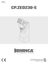
WIRE DIAGRAM
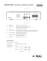
The electric connections shown in Fig. 1 are described in the following table:
Terminals Function Description
1-2 Input, Battery
Connection input for battery (1:+ / 2:-).
The connections marked a and b should be made with a cable featuring a 2.5mm
2
square
section.
3-4 Input, PV Panel
Input for the connection of the PV panel (3:+ / 4:-). The connections marked c and d
should be made with a cable featuring a 2.5mm
2
square section.
If the device is used in areas with little sun, more than one PV panels can be connected
in parallel. In this case, the panels must be of the same type, and the sum of Wp values
should not exceed 80 W.
5-6 24VAC/VDC
This voltage is used to supply the control unit in standard installations. The connections
marked c and d should be made with a cable featuring a 2.5mm
2
square section.
Output, 24VAC/VDC max. The system is powered only during operation.
7-8-9-10-11-12 Not use
13-14 IN, Step-by-Step Input, Step-by-Step control (Normally Open contact)
15-16 OUT, Step-by-Step
Output, Step-by-Step. Connect the Step-by-Step input to the control unit. It repeats the
status of the IN, Step-by- Step input.
17-18 IN SCA See “Automation status input” paragraph
19-20 Antenna
Connection of the antenna to the incorporated radio-receiver module
19 ANT: Signal / 20 SHIELD: Screen.
MF1-MF2
Power
Supply
In the event of failure or the batteries are completely down, the system can be supplied
through two fast-on connectors. Connect 24VAC 45VA minimum, by referring to an exter-
nal transformer.
Note: this input is used for the fast charge of the batteries connected to the terminal
board 1,2. It can be used for fully charge batteries before installation.
OPERATION
The SUNNY control unit provides for the charging of batteries through a photovoltaic panel. These batteries supply power to the control
unit of the automatic system.
A Step-by-Step control signal, sent to 13/14 input, or a control signal sent by a radio-transmitter, reactivates the control unit. With a
presettable delay-time, the unit starts the operation by responding to the Step-by-Step control on 15/16 outputs.
All transmitters can be memorised only in the built-in radio of SUNNY. It is not possible to use radio-receivers included in the control
unit. The J4 jumper should be CLOSED.
AUTOMATION STATUS INPUT
IMPORTANT! Read carefully!
Input terminals 17/18 allows the SUNNY control panel to know the automation status: if voltage is present, SUNNY provide power supply
to the control panel, if there is no voltage, the TOFF time countdown starts, when TOFF expires, SUNNY cuts off power supply to the
control panel, and SLEEP (energy saving) mode starts.
There are four different ways to manage 17/18 input terminals:
1) By using a “dry contact” (no tension) SCA output
2) By using a powered SCA output
3) By using an SWC (closing limit switch)
4) With BYPASS mode, that is without power supply interruption (no energy saving)
Dry SCA output*
In this case wire SCA as illustrated in Fig. 1, using batteries to bring a tension to the 17/18 input
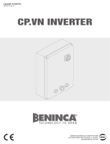
Powered SCA output*
In this case wire as illustrated in Fig. 2A, making a direct connection between SCA output and 17/18 input
*In case of any doubt please refer to the control panel manual, if the SCA output is a dry contact, the bulb is connected using the 24V power
supply output of the control panel itself, whereas if the SCA has an output tension, the bulb is connected directly to the SCA output.

10
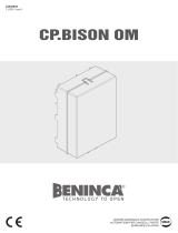
Using an SWC (closing limit switch)
If the control panel does not have a SCA output, it is possible to use a SWC limit switch wired as indicated in Fig. 2B
BYPASS mode
Bypass mode is used temporarily to allows SUNNY programmation (please see BYPASS mode paragraph), but it is possible to use the
SUNNY in continuous BYPASS mode if it is necessary to let the control panel work continuously.
This may be necessary in case of control panels which make an automatic autoset after a power failure (or cut off), in case that panels
and batteries are sized to allow uninterrupted power supply to the control panel or if you need to use a 24V powered accessory to ac-
tivate the automation. In this case the 17/18 terminals do not need to be connected
HOW TO PROGRAMME
The programming of the various functions of the control unit is carried out by using the LCD display on the control unit and presetting
the desired values in the programming menus described hereunder.
The Parameter Menu allows to preset a single-function number value, as for an adjustment trimmer.
Other special functions are included in the Parameter and Logics Menus and can vary according to the type of control unit or software
review.
USE OF <PG>/<+>/<-> PUSH-BUTTONS
Press the <PG> key to access presetting that can be changed by using + and – keys.
By pressing the < +> key, the Function Menu can be scrolled from bottom to top.
By pressing the <-> key, the Function Menu can be scrolled from top to bottom.
By pressing the <PG> key, access is enabled to any possible presetting to be modified.
The preset values can be changed by pressing <+> and <-> keys.
If the <PG> key is pressed again, the value is programmed and “PRG” is displayed.
See section “Programming Example”.
NOTE:
If <+> and <-> keys are pressed simultaneously from a Function Menu, this allows to return to the upper menu without making any
changes.
A pressure of the <-> key with display off equals to a Step-by-Step control signal.
When the card is switched on, the Software version is displayed for around 5 sec.
Keep either key <+> or key <-> pressed to speed up the increase/decrease of values.
After 30 sec wait, the control unit exits the programming mode and switches the display off.
WARNING:
If the D20 LED flashes every 4 seconds, this means that the SUNNY card is in the STAND-BY mode.
To re-activate the card and access programming, press the OK key for at least 4 seconds.
PARAMETERS, LOGICS AND SPECIAL FUNCTIONSI
The single functions available in the control unit are described in the following table.
MENU FUNCTION
MIN-MAX-(Default)
MEMO
PARAMETRI
Toff
Self-switching off time: after this time has elapsed, if the SCA off status is maintained
(control unit powered with motor off), SUNNY cuts off power supply to the control
unit.
1-240-(60s)
std
Start Delay: delay between the IN Step-by-Step input and its OUT Step-by-Step
response (this delay is required to leave the control unit enough time to switch on
and be therefore able to receive the control signal sent by SUNNY). Value expressed
in seconds, selectable by 0.5sec steps.
0: immediate response. 15: activation maximum time.
0-15-(2s)
tch
The relay switch time is preset on the OUT Step-by-Step output. 0.1-15-(1s)
MENU FUNCTION
STAT
VBAT
Instantaneous value of battery voltage.
E.g.: 24.0V.
Ibat
Instantaneous value of battery load/supply current.
Positive values (+) show load current.
Negative values (-) show supplied current.
E.g.: -1.1A.
VPHV
Instantaneous value of PV panel voltage.
IPHV
Instantaneous value of current supplied by the PV panel.
days
The number of operating days of the system is displayed. Value from 0 to 9999.
1 dy
The daily average value of battery load current is displayed.
This value is denominated in Ampère/h.

11
MENU FUNCTION
STAT
7 dy
The average value of battery load current over the last seven days is displayed.
This value is denominated in Ampère/h.
30dy
The average value of battery load current over the last thirty days is displayed.
This value is denominated in Ampère/h.
MENU FUNCTION
RES
RESET of the control unit. CAUTION!: The control unit is reset to default values.
If the <PG> button is pressed, the RES wording starts to flash. If the <PG> button is pressed again, the control unit
is reset.
Note: The transmitter codes of the receiver will not be erased.
FUSES
F1: Protection fuse of the PV panel: 5A automotive.
F2: Protection fuse of the batteries: 7.5A automotive.
BYPASS MODE
The “Bypass” mode is entered by pressing keys + and – simultaneously for at least 5 seconds.
ON: SUNNY keeps the control unit connected to it always on. In this way, parameters and logics of the control unit
can be preset, thus avoiding that the control unit enters the SLEEP mode.
N.B.: when the BYPASS mode is ON, the wording “ON” is displayed.
OFF: SUNNY works regularly.
DIAGNOSTICS
ON
ON : displayed fixed. This indicates that the control unit is on BYPASS mode allow setting operations.
ON
ON: flashing. This indicates that the control unit is powered and during an operation phase.
PP
This indicates the activation status of the PP input or the radio control.
The LED D20 shown in Figure 1 can feature three different status:
Off: the battery is not under charge or the PV panel is not connected.
On: the battery is under charge.
1 flash every 4 seconds: the SUNNY card is in STAND-BY mode. The battery is not under charge and the connected control unit is
not powered.
ERROR MESSAGES
In case of malfunctioning, the following messages can be displayed:
IOVF Error: overcurrent on battery. Check the correct operation of the connected control unit.
batt Check the battery status (disconnected or exhaust)).
HOW TO MEMORISE THE TRANSMITTER CODES
The control unit is equipped with an incorporated three-channel radio module, with 433.92 MHz frequency able to memorize up to 512
rolling-code transmitters or 1 programmable code.
The type of transmitter used can be selected by means of the B jumper:
with jumper closed: rolling-code only.
with jumper open: rolling-code and programmable codes.
To memorise a transmitter code, proceed as follows:
1 Press the P button of the radio receiver
2 The LED switches on with RED colour for approx. 3 sec.. The LED then switches off and on again.
If the transmitter code is to be memorised on the first channel (Step-by-Step function), press the transmitter key to be stored in
memory within 5 seconds.
3 If another transmitter code is to be memorised, press the desired key within 5 seconds. Conversely, wait for the receiver to exit the
programming mode.
To reset the receiver:
Cut-off power supply, press the P button and, while keeping it pressed, power the system again. The LED lights up with red fixed light.
After around 5 seconds, the LED starts flashing, with alternate colours. Release the button. The receiver is reset and all transmitter
codes are erased.
1/7