Page is loading ...


EZTag User Guide
Xilinx Development System
, XACT, XC2064, XC3090, XC4005, and XC-DS501 are registered trademarks of Xilinx. All XC-prefix
product designations, FastFLASH, FastCONNECT, EZTag, XACT-Floorplanner, XACT-Performance, XAPP,
XAM, X-BLOX, X-BLOX plus, XChecker, XDM, XDS, XEPLD, XPP, XSI, BITA, Configurable Logic Cell, CLC, Dual
Block, FastCLK, HardWire, LCA, Logic Cell, LogicProfessor, MicroVia, PLUSASM, SMARTswitch, UIM,
VectorMaze, VersaBlock, VersaRing, and ZERO+ are trademarks of Xilinx. The Programmable Logic Company
and The Programmable Gate Array Company are service marks of Xilinx.
IBM is a registered trademark and PC/AT, PC/XT, PS/2 and Micro Channel are trademarks of International Business
Machines Corporation. DASH, Data I/O and FutureNet are registered trademarks and ABEL, ABEL-HDL and ABEL-
PLA are trademarks of Data I/O Corporation. SimuCad and Silos are registered trademarks and P-Silos and P/C-
Silos are trademarks of SimuCad Corporation. Microsoft is a registered trademark and MS-DOS is a trademark of
Microsoft Corporation. Centronics is a registered trademark of Centronics Data Computer Corporation. PAL and
PALASM are registered trademarks of Advanced Micro Devices, Inc. UNIX is a trademark of AT&T Technologies,
Inc. CUPL, PROLINK, and MAKEPRG are trademarks of Logical Devices, Inc. Apollo and AEGIS are registered
trademarks of Hewlett-Packard Corporation. Mentor and IDEA are registered trademarks and NETED, Design
Architect, QuickSim, QuickSim II, and EXPAND are trademarks of Mentor Graphics, Inc. Sun is a registered
trademark of Sun Microsystems, Inc. SCHEMA II+ and SCHEMA III are trademarks of Omation Corporation. OrCAD
is a registered trademark of OrCAD Systems Corporation. Viewlogic, Viewsim, and Viewdraw are registered
trademarks of Viewlogic Systems, Inc. CASE Technology is a trademark of CASE Technology, a division of the
Teradyne Electronic Design Automation Group. DECstation is a trademark of Digital Equipment Corporation.
Synopsys is a registered trademark of Synopsys, Inc. Verilog is a registered trademark of Cadence Design Systems,
Inc.
Xilinx does not assume any liability arising out of the application or use of any product described or shown herein;
nor does it convey any license under its patents, copyrights, or maskwork rights or any rights of others. Xilinx
reserves the right to make changes, at any time, in order to improve reliability, function or design and to supply
the best product possible. Xilinx will not assume responsibility for the use of any circuitry described herein other
than circuitry entirely embodied in its products. Xilinx devices and products are protected under one or more of
the following U.S. Patents: 4,642,487; 4,695,740; 4,706,216; 4,713,557; 4,746,822; 4,750,155; 4,758,985;
4,820,937; 4,821,233; 4,835,418; 4,853,626; 4,855,619; 4,855,669; 4,902,910; 4,940,909; 4,967,107; 5,012,135;
5,023,606; 5,028,821; 5,047,710; 5,068,603; 5,140,193; 5,148,390; 5,155,432; 5,166,858; 5,224,056; 5,243,238;
5,245,277; 5,267,187; 5,291,079; 5,295,090; 5,302,866; 5,319,252; 5,319,254; 5,321,704; 5,329,174; 5,329,181;
5,331,220; 5,331,226; 5,332,929; 5,337,255; 5,343,406; 5,349,248; 5,349,249; 5,349,250; 5,349,691; 5,357,153;
5,360,747; 5,361,229; 5,362,999; 5,365,125; 5,367,207; 5,386,154; 5,394,104; 5,399,924; 5,399,925; 5,410,189;
5,410,194; 5,414,377; RE 34,363, RE 34,444, and RE 34,808. Other U.S. and foreign patents pending. Xilinx, Inc.
does not represent that devices shown or products described herein are free from patent infringement or from any
other third party right. Xilinx assumes no obligation to correct any errors contained herein or to advise any user of
this text of any correction if such be made. Xilinx will not assume any liability for the accuracy or correctness of
any engineering or software support or assistance provided to a user.
Xilinx products are not intended for use in life support appliances, devices, or systems. Use of a Xilinx product in
such applications without the written consent of the appropriate Xilinx officer is prohibited.
R

EZTag User Guide i
Preface
About This Manual
This manual describes Xilinx’s EZTag software, a tool used for In-
system progamming.
Before using this manual, you should be familiar with the operations
that are common to all Xilinx’s software tools: how to bring up the
system, select a tool for use, specify operations, and manage design
data. These topics are covered in the Development System Reference
Guide.
Manual Contents
This manual covers the following topics.
• Chapter 1, “Introduction,” provides an introduction to Xilinx
Boundary-scan and JTAG capabilities.
• Chapter 2, “EZTag Download Cable Options,” provides informa-
tion for connecting and using the XChecker Serial Cable or the
Parallel Download Cable to download and readback information
in-system.
• Chapter 3, “In-System Tutorial for PCs,” documents the basics of
using the interface to download programming to XC9500 family
devices in-system.
• Chapter 4, “EZTag with Workstations,” documents the basics of
using EZTag with from a workstation environment.
• Appendix A, “Error Messages,” provides a list of error messages
that EZTag may report. For most error messages a workaround is
suggested.

EZTag User Guide iii
Conventions
In this manual the following conventions are used for syntax clarifi-
cation and command line entries.
• Courier font indicates messages, prompts, and program files
that the system displays, as shown in the following example.
speed grade: -100
• Courier bold indicates literal commands that you must enter in
a syntax statement.
rpt_del_net=
• Italic font indicates variables in a syntax statement. See also, other
conventions used on the following page.
xdelay design
• Square brackets “[ ]” indicate an optional entry or parameter.
However, in bus specifications, such as bus [7:0], they are
required.
xdelay [option] design
• Braces “{ }” enclose a list of items from which you choose one or
more.
xnfprep designname ignore_rlocs={true|false}
• A vertical bar “|” separates items in a list of choices.
symbol editor [bus|pins]

Conventions
iv Xilinx Development System
Other conventions used in this manual include the following.
• Italic font indicates references to manuals, as shown in the
following example.
See the Development System Reference Guide for more information.
• Italic font indicates emphasis in body text.
If a wire is drawn so that it overlaps the pin of a symbol, the two
nets are not connected.
• A vertical ellipsis indicates repetitive material that has been
omitted.
IOB #1: Name = QOUT’
IOB #2: Name = CLKIN’
.
.
.
• A horizontal ellipsis “. . .” indicates that the preceding can be
repeated one or more times.
allow block blockname loc1 loc2 ... locn ;

EZTAG User Guide v
Contents
About This Manual........................................................................ i
Manual Contents........................................................................... i
Chapter 1 Introduction
Boundary Scan.............................................................................. 1-1
What is IEEE 1149.1................................................................ 1-1
What can it be used for............................................................ 1-1
How does it work...................................................................... 1-2
The TAP Controller............................................................. 1-2
The Instruction Register...................................................... 1-2
The Data Registers............................................................. 1-2
JTAG TAP Controller............................................................... 1-3
JTAG TAP Controller States............................................... 1-4
JTAG Instructions Supported in FastFLASH Parts.................. 1-5
Mandatory Boundary Scan Instructions.............................. 1-5
Optional Boundary Scan Instructions ................................. 1-6
FastFLASH Reconfiguration Instructions............................ 1-6
Device Operations......................................................................... 1-7
Data Security ........................................................................... 1-8
Feedback................................................................................. 1-8
Disconnecting .......................................................................... 1-8
Modifying a Programmed Design File........................................... 1-8
BSDL Summary ............................................................................ 1-8
JEDEC 3C Summary .................................................................... 1-9
Chapter 2 EZTag Download Cable Options
XChecker Hardware (Serial)......................................................... 2-1
Connecting the XChecker Cable................................................... 2-4
Connecting the XChecker Cable to Your Workstation............. 2-4
Connecting the XChecker Cable to Your PC........................... 2-4
Connection to Your Target System.......................................... 2-5

vi Xilinx Development System
EZTAG User Guide
Header Connector .............................................................. 2-5
Flying Lead Connectors...................................................... 2-5
Cable Connections ............................................................. 2-5
Connecting for System Operation............................................ 2-7
Parallel Download Cable............................................................... 2-8
Connecting the Parallel Download Cable ................................ 2-9
Connection to Your Target System.......................................... 2-9
Header Connector .............................................................. 2-9
Flying Lead Connectors...................................................... 2-10
Cable Connections ............................................................. 2-10
Connecting for System Operation............................................ 2-11
Chapter 3 In-System Tutorial for PCs
Introduction ................................................................................... 3-1
Cable Setup .................................................................................. 3-1
Selecting a Port for the Cable.................................................. 3-2
Device Chain................................................................................. 3-2
Configuring a Device In-System.................................................... 3-3
Modifying a Chain.................................................................... 3-5
Insert................................................................................... 3-6
Change............................................................................... 3-6
Delete ................................................................................. 3-6
Saving a Chain......................................................................... 3-7
Saving a Modified Chain.......................................................... 3-8
Data Security Selection............................................................ 3-8
Chapter 4 EZTag with Workstations
Using the EZTag Software............................................................ 4-1
EZTag Files.............................................................................. 4-1
design.jed ........................................................................... 4-2
eztag.pro............................................................................. 4-2
batch_file.cmd..................................................................... 4-2
device.bsd........................................................................... 4-2
Invoking EZTag........................................................................ 4-2
Downloading............................................................................ 4-2
Verifying................................................................................... 4-3
Command-Line Options................................................................ 4-4
–batch Batch Mode Operation................................................. 4-5
–h The Help Option.................................................................. 4-5
–pa Specify Part Type.............................................................. 4-5
–po Specify Port Name............................................................ 4-5

EZTAG User Guide vii
Contents
–v Verify Download and Readback........................................... 4-6
Interactive Mode Commands......................................................... 4-6
Batch — Execute in Batch Mode.............................................. 4-6
Examples............................................................................. 4-7
Baud — Specify Baud Rate...................................................... 4-7
Dump........................................................................................ 4-7
Erase ........................................................................................ 4-8
Exit — Terminate Session........................................................ 4-8
Functest.................................................................................... 4-8
Help — Online Help.................................................................. 4-8
Log — Send Screen Display to File.......................................... 4-9
Part — Specify Device Chain ................................................... 4-9
Partinfo ..................................................................................... 4-9
Port — Specify Download/Readback Port................................ 4-10
Program.................................................................................... 4-10
Quit — Terminate Session........................................................ 4-11
Reset — Reset Target LCA/Cable............................................ 4-11
Save — Save Option Settings.................................................. 4-11
Settings — Display Settings ..................................................... 4-12
Sys —Temporarily Exit to Operating System ........................... 4-12
Verify — Verify Target EPLD Bitstream.................................... 4-12
Troubleshooting Guide................................................................... 4-13
Communication......................................................................... 4-13
Improper Connections .............................................................. 4-14
Improper or Unstable VCC ....................................................... 4-14
Appendix A Error Messages
Introduction.................................................................................... A-1
Error Messages.............................................................................. A-1

EZTag User Guide 1-1
Chapter 1
Introduction
This chapter introduces you to the basic concepts of Xilinx JTAG
capabilities and the XC9500 series products.
Boundary Scan
What is IEEE 1149.1
Design complexity, difficulty of loaded board testing, and the limited
pin access of surface mount technology led industry leaders to seek
accord on a standard to support the solution of these problems.
Boundary Scan, formally known as IEEE Standard 1149.1, is prima-
rily a testing standard created to alleviate the growing cost of
designing and producing digital systems. The primary benefit of the
standard is the ability to transform extremely difficult printed circuit
board testing problems (that could only be attacked with ad-hoc
testing methods) into well-structured problems that software can
handle easily and swiftly.
The standard defines a hardware architecture and the mechanisms
for its use to solve the aforementioned problems.
What can it be used for
Although primarily a testing standard for on-chip circuitry, the prolif-
eration of the standard has opened to the door to a wide variety of
applications. The standard itself defines instructions that can be used
to perform functional and interconnect tests as well as built-in self
test procedures.
Vendor-specific extensions to the standard have been developed to
allow execution of maintenance and diagnostic applications as well
as programming algorithms for reconfigurable parts. It is the latter

Introduction
1-2 Xilinx Development System
that have been implemented (in addition to all the mandatory opera-
tions of the standard and some optional ones) in the FastFLASH
family.
How does it work
The top level schematic of the test logic defined by IEEE Std 1149.1
includes three key blocks:
The TAP Controller
This responds to the control sequences supplied through the test
access port (TAP) and generates the clock and control signals
required for correct operation of the other circuit blocks.
The Instruction Register
This shift register-based circuit is serially loaded with the instruction
that selects an operation to be performed.
The Data Registers
These are a bank of shift register based circuits. The stimuli required
by an operation are serially loaded into the data registers selected by
the current instruction. Following execution of the operation, results
can be shifted out for examination.
The JTAG Test Access Port (TAP) contains four pins that drive the
circuit blocks and control the operations specified. The TAP facilitates
the serial loading and unloading of instructions and data. The four
pins of the TAP are: TMS, TCK, TDI and TDO. The function of each
TAP pin is as follows:
TCK - this pin is the JTAG test clock. It sequences the TAP controller
as well as all of the JTAG registers provided in the XC95108.
TMS - this pin is the mode input signal to the TAP Controller. The
TAP controller is a 16-state FSM that provides the control logic for
JTAG. The state of TMS at the rising edge of TCK determines the
sequence of states for the TAP controller. TMS has an internal pull-up
resistor on it to provide a logic 1 to the system if the pin is not driven.
TDI -this pin is the serial data input to all JTAG instruction and data
registers. The state of the TAP controller as well as the particular
instruction held in the instruction register determines which register

Introduction
EZTag User Guide 1-3
is fed by TDI for a specific operation. TDI has an internal pull-up
resistor on it to provide a logic 1 to the system if the pin is not driven.
TDI is sampled into the JTAG registers on the rising edge of TCK.
TDO - this pin is the serial data output for all JTAG instruction and
data registers. The state of the TAP controller as well as the particular
instruction held in the instruction register determines which register
feeds TDO for a specific operation. Only one register (instruction or
data) is allowed to be the active connection between TDI and TDO for
any given operation. TDO changes state on the falling edge of TCK
and is only active during the shifting of data through the device. This
pin is three-stated at all other times.
Figure 1-1 JTAG Architecture
JTAG TAP Controller
The JTAG TAP Controller is a 16-state finite state machine, that
controls the scanning of data into the various registers of the JTAG
architecture. A state diagram of the TAP controller is shown in Figure

Introduction
1-4 Xilinx Development System
1-1. The state of the TMS pin at the rising edge of TCK is responsible
for determining the sequence of state transitions. There are two state
transition paths for scanning the signal at TDI into the device, one for
shifting in an instruction to the instruction register and one for
shifting data into the active data register as determined by the current
instruction.
JTAG TAP Controller States
Test-Logic-Reset. This state is entered on power-up of the device
whenever at least five clocks of TCK occur with TMS held high. Entry
into this state resets all JTAG logic to a state such that it will not inter-
fere with the normal component logic, and causes the IDCODE
instruction to be forced into the instruction register.
Run-Test-Idle. This state allows certain operations to occur
depending on the current instruction. For the XC9500 family, this
state causes generation of the program, verify and erase pulses when
the associated in-system programming (ISP) instruction is active.
Select-DR-Scan. This is a temporary state entered prior to
performing a scan operation on a data register or in passing to the
Select-IR-Scan state.
Select-IR-Scan. This is a temporary state entered prior to performing
a scan operation on the instruction register or in returning to the Test-
Logic-Reset state.
Capture-DR. This state allows data to be loaded from parallel inputs
into the data register selected by the current instruction on the rising
edge of TCK. If the selected data register does not have parallel
inputs, the register retains its state.
Shift-DR. This state shifts the data, in the currently selected register,
towards TDO by one stage on each rising edge of TCK after entering
this state.
Exit1-DR. This is a temporary state that allows the option of passing
on to the Pause-DR state or transitioning directly to the Update-DR
state.
Pause-DR. This is a wait state that allows shifting of data to be
temporarily halted.

Introduction
EZTag User Guide 1-5
Exit2-DR. This is a temporary state that allows the option of passing
on to the Update-DR state or returning to the Shift-DR state to
continue shifting in data.
Update-DR. This state causes the data contained in the currently
selected data register to be loaded into a latched parallel output (for
registers that have such a latch) on the falling edge of TCK after
entering this state. The parallel latch prevents changes at the parallel
output of these registers from occurring during the shifting process.
Capture-IR. This state allows data to be loaded from parallel inputs
into the instruction register on the rising edge of TCK. The least two
significant bits of the parallel inputs must have the value 01 as
defined by IEEE Std. 1149.1, and the remaining 6 bits are either hard-
coded or used for monitoring of the security and data protect bits.
Shift-IR. This state shifts the values in the instruction register
towards TDO by one stage on each rising edge of TCK after entering
this state.
Exit1-IR. This is a temporary state that allows the option of passing
on to the Pause-IR state or transitioning directly to the Update-IR
state.
Pause-IR. This is a wait state that allows shifting of the instruction to
be temporarily halted.
Exit2-IR. This is a temporary state that allows the option of passing
on to the Update-IR state or returning to the Shift-IR state to continue
shifting in data.
Update-IR. This state causes the values contained in the instruction
register to be loaded into a latched parallel output on the falling edge
of TCK after entering this state. The parallel latch prevents changes at
the parallel output of the instruction register from occurring during
the shifting process.
JTAG Instructions Supported in FastFLASH Parts
Mandatory Boundary Scan Instructions
BYPASS. The BYPASS instruction allows rapid movement of data to
and from other components on a board that are required to perform
test operations.

Introduction
1-6 Xilinx Development System
SAMPLE/PRELOAD. The SAMPLE/PRELOAD instruction allows a
snapshot of the normal operation of a components to be taken and
examined. It also allows data values to be loaded onto the latched
parallel outputs of the boundary scan shift register prior to the selec-
tion of other boundary-scan test instructions.
EXTEST. The EXTEST instruction allows testing of off-chip circuitry
and board level interconnections.
Optional Boundary Scan Instructions
INTEST. The INTEST instruction allows testing of the on-chip system
logic while the components are already on the board.
HIGHZ. The HIGHZ instruction forces all drivers into high imped-
ance states.
IDCODE. The IDCODE instruction allows blind interrogation of the
components assembled onto a printed circuit board to determine
what components exist in a product.
USERCODE. The USERCODE instruction allows a user-program-
mable identification code to be shifted out for examination. This
allows the programmed function of the component to be determined.
FastFLASH Reconfiguration Instructions
ISPEN. The ISPEN instruction activates the FastFLASH part for in-
system programming.
FPGM. The FPGM instruction is used to program the fuse locations at
a specified address.
FERASE. The FERASE instruction is used to perform an erase of a
block of fuse locations.
FVFY. The FVFY instruction is used to read the programming of the
fuse locations at a specified address.
ISPLD. The ISPLD instruction loads the programmed values into the
device memory. It then activates the device to operate according to
the programmed values.

Introduction
EZTag User Guide 1-7
Device Operations
Programming information is extracted from the JEDEC file generated
by the fitter software. The JEDEC file name defaults to
<
design
>.jed. If a full pathname is not provided the file of this
name is searched for along the XACT path.
Device operation options available to users are:
Program. Download the contents of the JEDEC file to the device
programming registers.
Program & Verify. Download contents of the JEDEC file to the device
programming registers. Configure the device and read back the
contents of device programming registers and compare them with
the JEDEC file. Report any differences to the user.
Program, Verify & Test. Same as Program & Verify (above) with the
addition of a Functional Test (see below).
Verify. Read back the contents of the device programming registers
and compare them with the JEDEC file.
Erase. Clear device configuration information.
Functional Test. Apply user-specified functional vectors from the
JEDEC file to the device, comparing results obtained against expected
values. Report any differences to the user.
Read Manufacturer’s ID. Read the contents of the JTAG IDCODE
register. Display contents for the user.
Read User Signature. This value will have been set by the user at
programming time. It is valid only after programming. This function
reads the contents of the JTAG USERCODE register and displays the
result for the user.
Bypass. Ignore this device when addressing devices in the JTAG
boundary scan chain.
Readback. Reads back the contents of device programming registers
and creates a new JEDEC file with the results.
Checksum. Reads back the contents of device programming registers
and calculates a checksum for comparison against the expected
value.

Introduction
1-8 Xilinx Development System
Data Security
All programming operations can optionally select to enable “Data
Protection” or Data Security” or both.
When enabled, Data Security disables reading the programmed
contents of a device (the device’s id and signature remain readable).
Data Protection allows only the reading of the programmed
data. The device contents cannot be altered.
When both Data Security and Data Protection are enabled,
the device can be neither read nor re-programmed.
Feedback
When using the PC-based graphical user interface, alert boxes at the
end of operation execution provide immediate feedback as the
success or failure of the specified operation. Detailed information
regarding failure is located in the system log file, and is provided for
both the PC and workstation based tool.
Disconnecting
Turn off the target system power before disconnecting the FastFLASH
BSCAN Download cable or the XChecker cable.
Modifying a Programmed Design File
The flow does not change for a modified programmed design file.
There are no shortcuts even with a minor change.
BSDL Summary
The Boundary Scan Description Language (BSDL) uses a subset of
VHDL to describe the boundary scan features of a component. One
BSDL file is required for each kind of boundary-scan device in the
system.
The BSDL files for FastFLASH devices are provided as part of the
product release. The user is responsible for providing BSDL files for
any non-FastFLASH parts used in the boundary-scan chain.

Introduction
EZTag User Guide 1-9
The system looks for BSDL files along the XACT path and in the
current working directory. The name of the BSDL file is assumed to
be <
device name
>.bsd.
JEDEC 3C Summary
This is the fuse map and functional verification vector file. This is an
ASCII file containing the configuration information and, optionally,
the vectors that can be used to verify the functional behavior of the
configured part. One JEDEC file is generated for each FastFLASH
device in the system.
The system looks for the JEDEC files along the XACT path and in the
current working directory. The name of the JEDEC file is assumed to
be <
design name
>.jed, but can be specified exactly by the user.

EZTag User Guide 2-1
Chapter 2
EZTag Download Cable Options
This chapter gives specific information about using EZTag with the
XChecker Cable and the Parallel Download Cable. You can use
EZTag to download, read back, verify design configuration data for
any device, and to probe internal logic states of an EPLD design.
Two cables are available from Xilinx. The first is a serial RS-232
known as the XChecker that you can connect to a serial port. The
second is the Parallel Download Cable that you can connect to a
printer port. This chapter documents both cables.
Note: If you have a Parallel Download Cable proceed to page 2-8.
XChecker Hardware (Serial)
The XChecker hardware consists of a cable assembly with internal
logic, a test fixture, and a set of headers to connect the cable to your
target system. If you have a serial system you may need a DB-9/DB-
25 adapter to connect to the host computer.
Using the XChecker hardware requires either a standard DB-9 or DB-
25 RS-232 serial port, or a parallel port. If you have a different serial
port connection, you need to provide an appropriate adapter. Figure

EZTag User Guide
2-2 Xilinx Development System
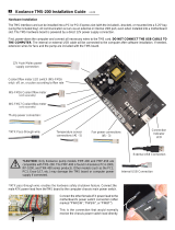
2-1 shows the XChecker cable hardware and accessories.
Figure 2-1 XChecker Hardware and Accessories
X1724a
XChecker
Cable Assembly
Flying Lead
Connector 1
Flying Lead
Connector 2
DB-25 Connector
DB-9 Connector
Connection to Host Computer
Connection to Target System
Test Fixture
Enlarged to show
mating plugged slots
May be required to connect
to host computer
Row 1
Row 2
+5VGnd
Connect to
FPGA
Demo Board
Key
Keyed Connection to Target System
/