Page is loading ...

Millerfi
OWNERS
MANUAL
SWINGARCTM
DS-1
2
And
DS-1
6
Read
and
follow
these
instructions
and
all
Give
this
manual
to
the
operator.
safety
blocks
carefully.
0
Have
only
trained
and
qualified
persons
install,
operate,
or
service
this
unit.
Call
your
distributor
if
you
do
not
understand
the
directions.
-
-
For
help,
call
your
distributor
or:
MILLER
Electric
Mfg.
Co.,
P.O.
Box
1079,
Appleton,
WI
54912
414-734-9821
May1995
Form:
OM-1584F
Effective
With
Serial
No.
KF834925
I
24
Volts,
10
Amperes,
50/60
Hertz
Boom
Mounted
Wire
Feeder
For
Use
With
CV/DC
Welding
Power
Source
With
Contactor
For
GMAW
And
FCAW
Welding
Rated
At
100
Volts,
750
Amperes,
100%
Duty
Cycle
Wire
Feed
Speed
Range:
50
To
780
ipm
(1.3
To
19.8
mpm)
Wire
Diameter
Range:
.023
To
1/8
in
(0.6
To
3.2
mm)
Vertical
Lift
Of
Boom:
Horizontal
To
60
Above
Honzontal
See
Rear
Cover
For
Options
And
Accessones
cover
5/94
ST-i
42
595-B
'
1995
MILLER
Electric
Mfg.
co.
PRINTED
IN
USA

MILLERS
TRUE
BLUETM
LIMITED
WARRANTY
Effective
January
1,1995
(Equipment
with
a
serial
number
preface
of
lCD
or
newer)
This
limited
wsrranty
supersedes
eli
previous
MILLER
wsrranties
end
is
exclusive
with
no
other
gusrsntees
or
warranties
expressed
or
implied.
LIMITED
WARRANTY
Subject
tothe
terms
end
conditions
below,
MILLER
Electric
Mfg.
Co.,
Appleton,
Wisconsin,
warrants
to
its
original
retell
purchaser
that
new
MILLER
equipment
sold
after
the
effective
date
of
this
limited
warranty
is
free
of
de
fects
in
material
and
workmanship
at
the
time
it
is
shipped
by
MILLER.
THIS
WAR
RANTY
IS
EXPRESSLY
IN
LIEU
OF
ALL
OTHER
WARRANTIES,
EXPRESS
OR
IMPLIED,
INCLUDING
THE
WARRANTIES
OF
MERCHANTABILITY
AND
FIT
NESS.
Within
the
warranty
periods
listed
below,
MILLER
will
repair
or
replace
any
war-
rented
parts
or
components
that
fail
due
to
such
defects
in
material
or
workmanship.
MILLER
must
be
notified
in
writing
within
thirty
(30)
days
of
such
defect
or
failure,
at
which
time
MILLER
will
provide
instructions
on
the
warranty
claim
procedures
to
be
followed.
MILLER
shall
honor
warranty
claims
on
warmnted
equipment
listed
below
in
the
event
of
such
a
failure
within
the
wsnenty
time
periods.
All
warranty
time
periods
stan
on
the
date
that
the
equipment
was
delivered
to
the
original
retail
purchaser,
or
one
year
after
the
equipment
is
sent
to
a
North
American
distributor
or
eighteen
months
after
the
equipment
is
sent
to
an
International
distributor.
1.
SYeeraParts3Yeam
Labor
*
Original
main
power
rectifiers
2.
3
Years
Parts
and
Labor
*
Trensformer/Rectifier
Power
Sources
Plasma
Arc
Cutting
Power
Sources
*
Semi-Automatic
and
Automatic
Wire
Feedere
Robots
3.
2
Yeam
Parts
and
Labor
Engine
Driven
Welding
Generatore
(NOTE:
Engines
are
warranted
separately
by
the
engine
manufacturer.)
*
Air
Compressors
4.
1
Year
Parts
and
Labor
Motor
Driven
Guns
Process
Controllers
-
IHPS
Power
Sources
Water
Coolant
Systems
HF
Units
Grids
Spot
Weldem
Load
Banks
SDX
Transformers
Running
Gearllmilem
*
Plasma
Cutting
Torches
(except
APT,
ZIPCUT
&
PLAZCUT
Models)
Tecumaeh
Engines
Deutz
Engines
(outside
North
America)
*
Field
Options
(NOTE:
Field
options
are
covered
underTrue
BtueTM
for
the
remaining
warranty
period
of
the
product
they
are
installed
in,
or
for
a
minimum
of
one
year
whichever
is
greater.)
5.
6
Months
Batteries
al
fi.
go
Days
Parts
and
Labor
MIG
Guna/TIG
Torches
APT,
Z1PCUT
&
PLAZCUT
Model
Plasma
Cutting
Torches
Remote
Controls
Accessory
Kits
Replacement
Parts
MILLERS
True
BIueTM
Umited
Warranty
shall
not
apply
to:
1.
Items
furnished
by
MILLER,
but
manufactured
by
othem,
such
as
engines
or
trade
accessories.
Theae
items
are
covered
bythe
manufacturers
warranty,
if
any.
2.
Consumable
components;
such
as
contact
tips,
cutting
nozzles,
contactore
and
relays
or
parts
that
fail
due
to
normal
wear.
3.
Equipment
that
has
been
modified
by
any
party
other
than
MILLER,
or
equip
ment
that
has
been
improperly
installed,
improperly
operated
or
misused
based
upon
industry
standards,
or
equipment
which
has
not
had
reasonable
and
necessary
maintenance,
or
equipment
which
has
been
used
for
operation
outside
of
the
specifications
for
the
equipment.
MILLER
PRODUCTS
ARE
INTENDED
FOR
PURCHASE
AND
USE
BY
COMMER
CIAIJINDUSTRIAL
USERS
AND
PERSONS
TRAINED
AND
EXPERIENCED
IN
THE
USE
AND
MAINTENANCE
OF
WELDING
EOUIPMENT.
In
the
event
of
a
warranty
claim
covered
by
this
warranty,
the
exclusive
remedies
shall
be,
at
MILLERS
option:
(1)
repair~
or
(2)
replacement;
or,
where
authorized
in
writing
by
MILLER
inappropriate
cases,
(3)
the
reasonable
coat
of
repair
or
replace
ment
at
an
authorized
MILLER
service
station;
or(4)
payment
of
or
credit
forthe
pur
chase
price
(less
reasonable
depreciation
based
upon
actual
use)
upon
return
of
the
goods
at
customers
risk
and
expense.
MILLERS
option
of
repair
or
replacement
wilt
be
FOB.,
Factoryat
Appleton,
Wisconsin,
or
FOB.
at
a
MILLER
authorized
ser
vice
facility
as
determined
by
MILLER.
Therefore
no
compensation
or
reimburse
ment
for
transportation
costa
of
any
kind
will
be
allowed.
TO
THE
EXTENT
PERMuTED
BY
LAW,
THE
REMEDIES PROVIDED
HEREIN
ARE
THE
SOLE
AND
EXCLUSIVE
REMEDIES.
IN
NO
EVENT
SHALL
MILLER
BE
LIABLE
FOR
DIRECT,
INDIRECT,
SPECIAL,
INCIDENTALOR
CONSEQUENTIAL
DAMAGES
(INCLUDING
LOSS
OF
PROFIT),
WHETHER
BASED
ON
CON
TRACT,
TORT
OR
ANY
OTHER
LEGAL
THEORY.
ANY
EXPRESS
WARRANTY
NOT
PROVIDED
HEREIN
AND
ANY
IMPLIED
WAR
RANTY,
GUARANTY
OR
REPRESENTATION
AS
TO
PERFORMANCE,
AND
ANY
REMEDY
FOR
BREACH
OF
CONTRACT
TORT
OR
ANY
OTHER
LEGAL
ThEORY
WHICH,
BUT
FOR
THIS
PROVISION,
MIGHTARISE
BY
IMPLICATION,
OPERATiON
OF
LAW,
CUSTOM
OF
TRADE
OR
COURSE
OF
DEALING,
IN
CLUDING
ANY
IMPLIED
WARRANTY
OF
MERCHANTABILITY
OR
FITNESS
FOR
PARTICULAR
PURPOSE,
WITh
RESPECT
TO
ANY
AND
ALL
EQUIPMENT
FURNISHED
BY
MILLER
IS
EXCLUDED
AND
DISCLAIMED
BY
MILLER.
Some
states
in
the
U.S.A.
do
not
allow
limitations
of
how
long
an
implied
warranty
lasts,
or
the
exclusion
of
incidental,
indirect,
special
or
consequential
damages,
so
the
above
limitation
or
exclusion
may
not
apply
to
you.
This
warranty
provides
ape
cif
ic
legal
tights,
and
other
rights
may
be
available,
but
may
vary
from
state
to
state.
In
Canada,
legislation
in
some
provinces
provides
for
certain
additional
warranties
or
remedies
other
than
as
stated
herein,
and
to
the
extent
that
they
may
not
be
waived,
the
limitations
and
exclusions
set
out
above
may
not
apply.
This
Umited
Warranty
provides
specific
legal
rights,
and
other
rights
may
be
available,
but
may
vary
from
province
to
province.
Before
Unpacking
equipment,
check
carton
for
any
damage
that
may
have
occurred
during
shipment.
Fi(e
any
claims
for
loss
or
damage
with
the
delivering
carrier.
Assistance
for
filing
or
settling
claims
may
be
obtained
from
distributor
and/or
equipment
manufacturers
Transportation
Department.
When
requesting
information
about
this
equipment,
always
provide
Model
Designation
and
Serial
or
Style
Number.
Use
the
following
spaces
to
record
Model
Designation
and
Serial
or
Style
Number
of
your
unit.
The
information
is
located
on
the
rating
label
or
nameplate,
Model
__________
Serial
or
Style
No.
Date
of
Purchase
I
J
?t)
LI
RECEIVING-HANDLING
miller
4/95

ARC
WELDING
SAFETY
PRECAUTIONS
ELECTRIC
SHOCK
can
kill.
Touching
live
electrical
parts
can
cause
fatal
shocks
or
severe
bums.
The
electrode
and work
circuit
is
electrically
live
whenever
the
output
is
on.
The
input
power
circuit
and
machine
internal
circuits
are
also
live
when
power
is
on.
In
semiautomatic
orautomatic
wire
welding,
the
wire,
wire
reel,
drive
roll
housing,
and
all
metal
parts
touching
the
welding
wire
are
electrically
live.
Incorrectly
installed
or
improperly
grounded
equipment
is
a
hazard.
1.
Do
not
touch
live
electrical
parts.
2.
Wear
dry,
hole-free
insulating
gloves
and
body
protection.
3.
Insulate
yourself
from
work and
ground
using
dry
insulating
mats
or
covers
big
enough
to
prevent
any
physical
contact
with
the
work
or
ground.
4.
Disconnect
input
power
or
stop
engine
before
installing
or
servicing
this
equipment.
Lockout/tagout
input
poweraccording
to
OSHA
29
CFR
1910.147
(see
Safety
Standards).
5.
Properly
install
and
ground
this
equipment
according
to
its
Owners
Manual
and
national,
state,
and
local
codes.
6.
Always
verify
the
supply
ground
check
and
be
sure
that
input
power
cord
ground
wire
is
properly
connected
to
ground
ARC
WELDING
can
be
hazardous.
terminal
in
disconnect
box
or
that
cord
plug
is
connected
to
a
properly
grounded
receptacle
outlet.
7.
When
making
input
connections,
attach
proper
grounding
conductor
first
double-check
connections.
8.
Frequently
inspect
input
power
cord
for
damage
or
bare
wiring
replace
cord
immediately
if
damaged
bare
wiring
can
kill.
9.
Turn
oft
all
equipment
when
not
in
use.
10.
Do
not
use
wom,
damaged,
undersized,
or
poorly
spliced
cables.
11.
Do
not
drape
cables
over
your
body.
12.
If
earth
grounding
of
the
workpiece
is
required,
ground
it
directly
with
a
separate
cable
do
not
use
work
clamp
or
work
cable.
13.
Do
not
touch
electrode
if
you
are
in
contact
with
the
work,
ground,
or
another
electrode
from
a
difterent
machine.
14.
Use
only
well-maintained
equipment.
Repair
or
replace
damaged
parts
at
once.
Maintain
unit
according
to
manual.
15.
Wear
a
safety
harness
if
working
above
floor
level.
16.
Keep
all
panels
and
covers
securely
in
place.
17.
clamp
work
cable
with
good
metal-to-metal
contact
to
workpiece
or
worktable
as
near
the
weld
as
practical.
£~
WARNING
PROTECT
YOURSELF
AND
OTHERS
FROM
POSSIBLE
SERIOUS
INJURY
OR
DEATH.
KEEP
CHILDREN
AWAY.
PACEMAKER
WEARERS
KEEP
AWAY
UNTIL
CONSULTING
YOUR
DOCTOR.
In
welding,
as
in
most
jobs,
exposure
to
certain
hazards
occurs.
Welding
is
safe
when
precautions
are
taken.
The
safety
information
given
below
is
only
a
summary
of
the
more
complete
safety
information
that
will
be
found
in
the
Safety
Standards
listed
on
the
next
page.
Read
and
follow
all
Safety
Standards.
HAVE
ALL
INSTALLATION,
OPERATION,
MAINTENANCE,
AND
REPAIR
WORK
PERFORMED
ONLY
BY
QUALIFIED
PEOPLE.
ARC
RAYS
can
burn
eyes
and
skin;
ARC
RAYS
NOISE
can
damage
hearing;
FLYING
(,~
SLAG
OR
SPARKS
can
injure
eyes.
2.
Wear
a
welding
helmet
fitted
with
a
proper
shade
of
filter
to
protect
yourface
and
eyes
when
welding
orwatching
(see
ANSI
Arc
rays
from
the
welding
process
produce
intense
Z49.1
and
Z87.1
listed
in
Safety
Standards).
visible
and
invisible
(ultravioletand
infrared)
rays
that
3.
Wear
approved
safety
glasses
with
side
shields.
can
burn
eyes
and
skin.
Noise
from
some
processes
can
damage
hearing.
Chipping,
grinding,
and
welds
4.
Use
protective
screens
or
barriers
to
protect
others
from
flash
cooling
throw
oft
pieces
of
metal
or
slag.
and
glare;
warn
others
not
to
watch
the
arc.
NOISE
5.
Wear
protective
clothing
made
from
durable,
flame-resistant
1.
Use
approved
ear
plugs
or
ear
mufts
if
noise
level
is
high.
material
(wool
and
leather)
and
foot
protection.
to
your
health.
wearing
an
air-supplied
respirator.
Always
have
a
trained
r
FUMES
AND
GASES
can
be
hazardous
5.
Work
in
a
confined
space
only
if
it
is
well
ventilated,
or
while
Welding
produces
fumes
and
gases.
Breathing
watchperson
nearby.
Welding
fumes
and
gases
can
displace
these
fumes
and
gases
can
be
hazardous
to
your
air
and
lower
the
oxygen
level
causing
injury
or
death.
Be
sure
health.
the
breathing
air
is
safe.
.-s
6.
Do
not
weld
in
locations
near
degreasing,
cleaning,
or
spraying
1.
Keep
your
head
out
of
the
fumes.
Do
not
breathe
the
fumes.
operations.
The
heat
and
rays
of
the
arc
can
react
with
vapors
to
2.
If
inside,
ventilate
the
area
and/or
use
exhaust
at
the
arc
to
form
highly
toxic
and
irritating
gases.
remove
welding
fumes
and
gases.
7.
Do
not
weld
on
coated
metals,
such
as
galvanized,
lead,
or
3.
If
ventilation
is
poor,
use
an
approved
air-supplied
respirator.
cadmium
plated
steel,
unless
the
coating
is
removed
from
the
4.
Read
the
Material
Safety
Data
Sheets
(MSDSs)
and
the
weld
area,
the
area
is
well
ventilated,
and
if
necessary,
while
manufacturers
instruction
for
metals,
consumables,
coatings,
wearing
an
air-supplied
respirator.
The
coatings
and
any
metals
cleaners,
and
degreasers.
containing
these
elements
can
give
oft
toxic
fumes
if
welded.
CYLINDERS
can
explode
if
damaged.
4.
Never
drape
a
welding
torch
over
a
gas
cylinder.
Shielding
gas
cylinders
contain
gas
under
high
pressure.
If
damaged,
a
cylinder
can
explode.
Since
gas
cylinders
are
normally
part
of
the
welding
process,
be
sure
to
treat
them
carefully.
5.
6.
7.
Never
allow
a
welding
electrode
to
touch
any
cylinder.
Never
weld
on
a
pressurized
cylinder
explosion
will
result.
Use
only
correct
shielding
gas
cylinders,
regulators,
hoses,
and
fittings
designed
for
the
specific
application;
maintain
them
and
associated
parts
in
good
condition.
1.
Protect
compressed
gas
cylinders
from
excessive
heat,
8.
Turn
face
away
from
valve
outlet
when
opening
cylinder
valve.
mechanical
shocks,
slag,
open
flames,
sparks,
and
arcs.
9.
Keep
protective
cap
in
place
over
valve
except
when
cylinder
is
2.
Install
cylinders
in
an
upright
position
by
securing
to
a
stationary
in
use
or
connected
for
use.
support
or
cylinder
rack
to
prevent
falling
or
tipping.
io.
Read
and
follow
instructions
on
compressed
gas
cylinders,
3.
Keep
cylinders
away
from
any
welding
or
other
electrical
associated
equipment,
and
CGA
publication
P-i
listed
in
Safety
circuits.
Standards.
srl.1.1
2/94

WELDING
can
cause
fire
or
explosion.
Welding
on
closed
containers,
such
as
tanks,
drums,
or
pipes,
can
cause
them
to
blow
up.
Sparks
can
fly
oft
from
the
welding
arc.
The
flying
sparks,
hot
workpiece,
and
hot
equipment
can
cause
fires
and
burns.
Accidental
contact
of
electrode
to
metal
objects
can
cause
sparks,
explosion,
overheating,
or
fire.
Check
and
be
sure
the
area
is
safe
before
doing
any
welding.
1.
Protect
yourself
and
others
from
flying
sparks
and
hot
metal.
2.
Do
not
weld
where
flying
sparks
can
strike
flammable
material.
3.
Remove
all
flammables
within
35
ft
(10.7
m)
of
the
welding
arc.
If
this
is
not
possible,
tightly
cover
them
with
approved
covers.
4.
Be
alert
that
welding
sparks
and
hot
materials
from
welding
can
easily
go
through
small
cracks
and
openings
to
adjacent
areas.
5.
Watch
for
fire,
and
keep
a
fire
extinguisher
nearby.
6.
Be
aware
that
welding
on
a
ceiling,
floor,
bulkhead,
or
partition
can
cause
fire
on
the
hidden
side.
7.
Do
not
weld
on
closed
containers
such
as
tanks,
drums,
or
pipes,
unless
they
are
properly
prepared
according
to
AWS
F4.1
(see
Safety
Standards).
8.
Connect
work
cable
to
the
work
as
close
to
the
welding
area
as
practical
to
prevent
welding
current
from
traveling
long,
possibly
unknown
paths
and
causing
electric
shock
and
fire
hazards.
9.
Do
not
use
welder
to
thaw
frozen
pipes.
10.
Remove
stick
electrode
from
holder
or
cut
off
welding
wire
at
contact
tip
when
not
in
use.
11.
Wear
oil-free
protective
garments
such
as
leather
gloves,
heavy
shirt,
cuffless
trousers,
high
shoes,
and
a
cap.
12.
Remove
any
combustibles,
such
as
a
butane
lighter
or
matches,
from
your
person
before
doing
any
welding.
ENGINE
EXHAUST
GASES
can
kill.
MOVING
PARTS
can
cause
injury.
Moving
parts,
such
as
fans,
rotors,
and
belts
can
cut
fingers
and
hands
and
catch loose
clothing.
Keep
all
doors,
panels,
covers,
and
guards
closed
and
securely
in
place.
Stop
engine
before
installing
or
connecting
unit
SPARKS
can
cause
BAT1ERY
GASES
TO
EXPLODE;
BAT1ERY
ACID
can
burn
eyes
and
skin.
Batteries
contain
acid
and
generate
explosive
gases.
STEAM
AND
PRESSURIZED
HOT
COOLANT
can
burn
face,
eyes,
and
skin.
It
is
best
to
check
coolant
level
when
engine
is
cold
to
avoid
scalding.
ENGINES
can
be
hazardous.
3.
Have
only
qualified
people
remove
guards
or
covers
for
maintenance
and
troubleshooting
as
necessary.
4.
To
prevent
accidental
starting
during
servicing,
disconnect
negative
()
battery
cable
from
battery.
5.
Keep
hands,
hair,
loose
clothing,
and
tools
away
from
moving
parts.
6.
Reinstall
panels
or
guards
and
close
doors
when
servicing
is
finished
and
before
starting
engine.
1.
Always
wear
a
face
shield
when
working
on
a
battery.
2.
Stop
engine
before
disconnecting
or
connecting
battery
cables.
3.
Do
not
allow
tools
to
cause
sparks
when
working
on a
battery.
4.
Do
not
use
welder
to
charge
batteries
or
jump
start
vehicles.
5.
Observe
correct
polarity
(+
and
)
on
batteries.
1.
If
the
engine
is
warm
and
checking
is
needed,
follow
steps
2
and
3.
2.
Wear
safety
glasses
and
gloves
and
put
a
rag
over
cap.
3.
Turn
cap
slightly
and
let
pressure
escape
slowly
before
completely
removing
cap.
PRINCIPAL
SAFETY
STANDARDS
Safety
in
Welding
and
Cutting,
ANSI
Standard
Z49.
1,
from
American
Welding
Society,
550
N.W.
LeJeune
Rd,
Miami
FL
33126
Safety
and
Health
Standards,
OSHA
29
CFR
1910,
from
Superinten
dent
of
Documents,
U.S.
Government
Printing
Office,
Washington,
D.C.
20402.
Recommended
Safe
Practices
for
the
Preparation
for
Welding
and
Cutting
of
Containers
That
Have
Held
Hazardous
Substances,
Ameri
can
Welding
Society
Standard
AWS
F4.1
from
American
Welding
So
ciety,
550
N.W.
LeJeune
Rd, Miami,
FL
33126
National
Electrical
Code,
NFPA
Standard
70,
from
National
Fire
Pro
tection
Association,
Batterymarch
Park,
Quincy,
MA
02269.
Safe
Handling
of
Compressed
Gases
in
Cylinders,
CGA
Pamphlet
P-i,
from
Compressed
Gas
Association,
1235
Jefferson
Davis
High
way,
Suite
501,
Arlington,
VA
22202.
Code
for
Safety
in
Welding
and
Cutting,
CSA
Standard
Wi
17.2,
from
Canadian
Standards
Association,
Standards
Sales,
178
Rexdale
Bou
levard,
Rexdale,
Ontario,
Canada
M9W
1
R3.
Safe
Practices
ForOccupation
And
Educational
Eye
And
Face
Protec
tion,
ANSI
Standard
Z87.i,
from
American
National
Standards
Institute,
1430
Broadway,
New
York,
NY
10018.
Cutting
And
Welding
Processes,
NFPA
Standard
51
B,
from
National
Fire
Protection
Association,
Batterymarch
Park,
Quincy,
MA
02269.
a
WARNING
1.
Use
equipment
outside
in
open,
well-ventilated
areas.
Engines
produce
harmful
exhaust
gases.
2.
If
used
in
a
closed
area,
vent
engine
exhaust
outside
and
away
from
any
building
air
intakes.
ENGINE
FUEL
can
cause
fire
or
explosion.
Engine
fuel
is
highly
flammable.
3.
4.
Do
not
overfill
tan
Do
not
spill
fuel.
engine.
k
all
If
fuel
ow
room
fo
is
spilled,
r
fuel
to
expand.
clean
up
before
starting
1.
Stop
engine
and
let
it
cool
oft
before
checking
or
adding
fuel.
2.
Do
not
add
fuel
while
smoking
or
if
unit
is
near
any
sparks
or
open
flames.
srl.1.1
2/94

CONSIGNES
DE
SECURITE
POUR
LE
SOUDAGE
A
LARC
UN
CHOC
ELECTRIQUE
peut
tuer.
(in
simple
contact
avec
des
piŁces
Olectriques
pout
provoquer
une
electrocution
ou
des
blessures
graves.
LØlectrode
et
le
circuit
do
soudage
sont
sous
tension
des
quo
lappareil
est
sur
ON.
Le
circuit
dentrØe
et
los
circuits
intemes
do
Iappareil
sont
egalement
sous
tension
a
ce
moment-l.
En
soudage
semi-automatique
ou
automatique,
le
fil,
le
dØvidoir,
0
logement
des
galets
dentraInementet
los
piŁces
mØtalliques
en
contact
avec
le
fil
do
soudage
sont
sous
tension.
Des
matŁriels
mal
installØs
ou
mal
mis
a
Ia
terre
presentent
un
danger.
1.
No
jamais
toucher
les
piŁces
electriques
sous
tension.
2.
Porter
des
gants
et
des
vOtemonts
do
protection
secs
no
comportant
pas
do
trous.
3.
Sisoler
do
Ia
piŁce
et
de
Ia
terre
au
moyen
de
tapis
ou
dautres
moyens
isolants
suffisamment
grands
pour
empŁcher
le
contact
physique
Øventuel
avec
Ia
piŁce
ou
Ia
terre.
4.
Couper
lalimentation
ou
arrŒter
le
moteur
avant
do
procedor
a
linstallation,
a
Ia
reparation
ou
a
lentretien
do
lappareil.
DØverrouiller
lalimentation
solon
Ia
norme
OSHA
29
CFR
1910.147
(voir
normes
do
secuntO).
5.
Installeret
mettre
ala
terre
correctement
cot
appareil
conformØment
a
son
manuel
dutilisation
et
au
codes
nationaux,
provinciaux
et
municipaux.
6.
Toujours
vŁnfier
Ia
terre
du
cordon
dalimentation
Verifier
et
sassurer
Quo
0
fil
do
terre
du
cordon
dalimentation
est
bien
raccordØ
ala
borne
do
terre
du
sectionneur
ou
quo
Ia
fiche
du
cordon
est
raccordOe
a
une
priso
correctoment
mise
a
Ia
terre.
7.
En
effoctuant
los
raccordomentsdentrØefixerdabordleconductour
do
mise
a
Ia
terre
appropn
ot
contra-verifier
los
connexions.
8.
Verifier
frequemment
le
cordon
dalimontation
pourvoirsiI
nest
pas
endommage
ou
dOnudØ
romplacor
10
cordon
immØdiatoment
sil
est
endommage
un
cable
dOnudŁ
peut
provoquer
une
electrocution.
9.
Mettre
lappareil
hors
tension
quand
on
no
Iutilise
pas.
10.
Ne
pas
utiliser
des
cables
uses,
endommages,
do
grossour
insuffisante
ou
mal
ØpissŁs.
11.
Ne
pas
enroulor
los
cables
autour
du
corps.
12.
Si
Ia
piŁce
soudØe
doit
Otre
mise
ala
terre,
le
faire
diroctement
avec
un
cable
distinct
no
pas
utiliser
10
connoctour
do
piŁce
ou
10
cable
do
retour.
13.
Ne
pas
toucher
lŁlectrode
quand
on
ost
en
contact
avec
a
piŁce,
Ia
terre
ou une
electrode
provenant
dune
autre
machine.
14.
Nutiliser
quun
materiel
en
bon
Øtat.
Reparor
ou
remplacer
sur-le-champ
les
piŁces
ondommagees.
Entretenir
lappareil
conformement
ace
manuel.
15.
Porter
un
hamais
do
sØcuntØ
quand
on
travaillo
on
hauteur.
16.
Maintonir
solidement
en
place
tousles
panneaux
ot
capots.
17.
Fixer
10
cable
do
rotourde
facon
a
obtenir
un
bon
contact
mOtal-mOtal
avec
Ia
piŁce
~
soudorou
latable
do
travail,
le
plus
prØs
possible
do
Ia
soudure.
a
MISE
EN
GARDE
LE
SOUDAGE
A
LARC
peut
Œtre
darigereux.
SE
PROTEGER
ET
PROTEGER
LES
AUTRES
CONTRE
LES
BLESSURES
GRAVES
VOIRE
MORTELLES.
TENIR
LES
ENFANTS
A
LECART.
LES
PERSONNES
GUI
PORTENT
UN
STIMULATEUR
CARDIAQUE
NE
DOIVENT
PAS
NON
PLUS
SAPPROCHER
DU
POSTE
DE
SOUDAGE,
A
MOINS
DAVOIR
CONSULTE
UN
MEDEC~N.
Le
soudage,
comme
Ia
plupart
des
travaux,
presente
certains
dangers.
Par
contre,
0
soudage
peut
Otre
effectuØ
en
toute
sOcuritØ
quand
on
prend
les
mesures
qul
simposent.
Los
consignes
de
sØcuntØ
donnees
ci-apres
ne
font
quo
rØsumer
information
contenue
dans
es
normes
de
sOcuritØ
ØnumØrØes
a
Ia
page
suivante.
Lire
et
respecter
toutes
ces
norrnes
do
sØcuritØ.
LINSTALLATION,
LUTILISATION,
LENTRETIEN
ET LES
REPARATIONS
NE
DOIVENT
ETRE
CONFIES
QUA
DES
PERSONNES
QUALIFIEES
LE
RAYONNEMENT
DE
LARC
peut
brler
les
RAYONNEMENT
DE
LARC
yeux
et
Ia
peau.
Le
BRUIT
peut
endommager
IouIe;
les
PROJECTIONS
DE
LAITIER
OU
LES
appropriee
pour
protOger
10
visage
et
les
yeux
quand
on
soude
ou
/p~
ETINCELLES
peuvent
blesser
les
yeux.
2.
Porter
un
masque
a
serre-tŒte
muni
dun
verre
filtrant
de
nuance
Larc
do
soudage
produit
des
rayons
visibles
et
invisibles
observe
Ia
travail
do
soudage
(voir
los
normes
ANSI
Z49.
1
et
Z87.1
intenses
(ultraviolots
et
infrarougos)
qui
pouvont
brler
donnØos
sous
Ia
rubflque
Pnncipales
normes
do
sØcuntO).
les
yeux
et
Ia
peau.
Le
bruit
produit
par
certains
procOdØs
peut
endommager
louie.
Des
protections
de
metal
ou
do
3.
Porter
des
lunettes
de
sŁcuntO
approuvØes
avoc
Øcrans
latØraux.
laitier
sont
produites
par
10
piquage,
le
meulage
ou
le
refroidissement
dos
soudures.
4.
Utiliser
des
paravents
ou
des
barriŁres
de
protection
pour
proteger
los
personnes
a
proximite
contra
los
coups
darc
et
IOblouissemont;
BRUIT
avertir
los
autros
personnes
do
ne
pas
regarder
larc.
1.
Utiliser
des
bouche-oroilles
ou
des
serre-tOte
antibruit
approuvØs
si
5.
Porter
des
vØtements
do
protection
en
tissu
ignifuge
durable
(lamb
et
le
niveau
de
bruit
est
ØlevØ.
cuir)
et
des
chaussures
do
sØcufltO.
I
LES
VAPEURS
ET
LES
FUMEES
peuvent
Œtre
5.
Ne
travailler
dans
un
espace
confine
quo
sil
est
bien
ventilØ,
ou
en
dangereuses
pour
Ia
sante.
portantunappareilrespiratoireaadductiondairpur.
Demanderun
observatour
ayant
reu
Ia
bonne
formation
do
toujours
se
tenir
a
t
,__~,.
Le
soudage
produit
des
vapeurs
ot
des
fumŁes
quil
est
proximitŁ.
Los
vapeurs
et
fumOes
do
soudage
pouvent
deplacer
lair
dangereux
do
respirer.
et
abaisser
le
niveau
doxygene
et
causerdos
blessures
graves
voiro
mortelles.
Sassurer
quo
lair
est
propre
a
Ia
respiration.
1.
Garder
Ia
tŒte
a
IextØrieur
des
vapeurs
et
des
fumØes
et
no
pas
los
6.
Ne
pas
souder
a
proximite
dopØrations
do
dØgraissage,
do
respirer.
nettoyage
ou
do
pulvensation.
La
chaleur
et
les
rayons
do
Iarc
2.
A
IintØneur,
ventiler
lo
poste
do
travail
ou
utiliser
un
dispositif
place
peuvont
reagir
avec
los
vapours
pour
former
des
gaz
haubement
toxiquos
et
irritants.
au
niveau
do
larc
pour
evacuer
los
vapeurs
et
fumØes
do
soudage.
7.
Ne
pas
souder
sur
des
mØtaux
revŒtus
comme
lacier
galvanisO,
au
3.
Si
Ia
ventilation
ost
mauvaiso,
utiliser
un
appareil
respiratoiro
a
p10mb
ou
cadmiØ
a
moms
quo
Ia
piŁce
nait
ØtØ
entiŁrement
dØcapØo,
adduction
dair
pur
approuve.
quo
le
poste
de
travail
soit
bien
ventilØ.
Sil
y
a
lieu,
porter
un
apparoil
4.
Consulter
los
fiches
signalOtiques
ot
los
consignes
du
fabricant
rospiratoireaadductiondairpur.
LesrevOtementsotlesmŁtauxqui
relatives
au
mOtaux,
produits
dapport,
revØtements,
nettoyants
ot
contiennent
do
tels
ØlØments
peuvent
dØgager
des
vapeurs
toxiques
degraissants.
lors
du
soudago.
.J
LES BOUTEILLES
peuvent
exploser
Si
elles
4.
Ne
jamais
poser
un
chalumeau
soudeur
sur
une
bouteille
do
gaz.
~.
sont
endommagees.
5.
Ne
jamais
laisser
une
electrode
de
soudage
toucher
uno
bouteillo.
;~-
Les
bouteilles
contenant
des
gaz
do
protection
sont
a
6.
Ne
jamais
soudor
sur
une
bouteillo
sous
pression
:
0110
exploserait.
~.
haute
prassion.
Une
bouteillo
endommagee
pout
7.
Nutilisor
quo
des
boubeilles
de
g~
do
protection,
dos
dØtendeurs,
explosor.
Etant
donnØ
que
los
bouteilles
do
gaz
font
des
tuyaux
souplos
et
des
raccords
appropriØs
concus
pour
normalement
partie
du
materiel
do
soudago,
les
traitor
Iapplication
particuliŁre;
conserver
ces
matØrlels
ot
ours
piŁces
on
avec
le
plus
grand
SO~fl.
bon
Łtat.
1.
Protegor
les
bouteilles
do
gaz
comprime
contra
Ia
chalour
intense,
8.
Eloignor
le
visage
do
Ia
sortie
du
robinet
do
Ia
boutoille
quand
on
los
chocs,
0
laitier,
los
flammes
nues,
les
Łtincellos
et
larc.
louvre.
2.
Placer
los
bouteilles
ala
vorticale
en
los
fixant
a
un
support
fixe
ou
a
9.
Replacer
Ia
chapoau
sur
Ia
bouteille
apres
utilisation.
un
chariot
pour
Øviter
quolles
no
tombent
ou
no
basculent.
10.
Lire
ot
suivre
los
consignes
relatives
aux
bouteilles
do
gaz
compnme,
3.
Tenir
los
bouteillos
a
lecart
du
poste
do
soudage
ou
dautres
circuits
au
materiel
connexe
ainsi
que
Ia
publication
P-i
do
Ia
CGA
donnØe
electriques.
sous
Ia
rubnquo
Principales
norrnes
de
sŁcuntŁ.
sri
.1.1
2/94

LE
SOUDAGE
peut
causer
un
incendie
ou
une
explosion.
Ne
pas
souder
sur
des
recipients
fermØs
comme
des
reservoirs,
des
Wits
ou
des
tuyaux:
us
peuvent
oxploser.
Larc de
soudage
peut
produire
dos
Øtincelles.
Des
Øtincelles,
une
piŁce
chaudo
et
un
materiel
chaud
peuvent
provoquer
des
incendies
et
des
blessures.
Le
contact
accidentel
de
lØlectrode
sur
des
objets
metalliques
peut
produire
des
Øtincelles,
explosion,
Ia
surchauffe
ou
un
incendie.
Sassurer
que
le
lieu
ne
prØsente
pas
de
danger
avant
deffectuer
le
soudage.
1.
Se
protØgeret
proteger
lespersonnes
a
proximitØ
des
Øtincelles
et
du
metal
chaud.
2.
Ne
pas
souder
dans
un
endroit
00
les
Øtincelles
peuvent
atteindre
des
matOrlaux
inflammables.
3.
Enlevertoutes
les
matiŁres
inflammables
dans
un
rayon
de
moms
de
10
m
de
larc.
Si
cela
nest
pas
possible,
bien
les
recouvriren
utilisant
des
baches
approuvØes.
4.
Prendre
garde
que
los
Øtincelles
et
les
projections
ne
penetrent
dans
des
zones
adjacentes
en
sinfiltrant
dans
des
potites
fissures
et
ouvertures.
5.
Prendre
garde
aux
incendies
et
toujours
avoir
un
extincteur
a
proximite.
6.
Se
rappelerque
si
on
soude
sur
un
plafond,
un
plancher,
une
cloison
ou
autre,
le
feu
peut
prendre
de
lautre
ctØ.
7.
Ne
pas
souder
sur
des
recipients
fermØs
commo
des
reservoirs,
des
fOts
ou
des
tuyaux
a
moms
quils
ne
solent
prepares
de
tacon
appropriee
confom,Øment
ala
norme
F4.
1
de
lAWS
(voir
Ia
rubrique
Principales
normos
de
securitO).
8.
Raccorder
le
cable
de
retour
a
Ia
piece,
le
plus
pres
possible
de
Ia
zone
de
soudage,
pour
ompecher
que
le
courant
de
soudage
no
suive
une
trajectoire
longue
et
Øventuellement
inconnue
et
quil
ne
provoque
des
nsques
dOlectrocution
et
dincendie.
9.
Ne
pas
utiliser
le
chalumeau
soudeur
pour
degeler
des
tuyaux.
10.
Enlever
electrode
enrobØe
du
porte-electrode
ou
couper
le
fil
de
soudage
au
ras
du bec
contact
quand
on
ne
lutilise
pas.
ii.
Porter
des
vŒtements
de
protection
non
huileux
comme
des
gants
en
cuir,
une
chemise
Øpaisse,
des
pantalons
sans
revers,
des
chaussures
montantes
et
un
casque.
12.
Ne
pas
porter
des
matiŁres
combustibles
sur
soi
comme
un
briquet
a
gaz
ou
des
allumettes
quand
on
soude.
LES
GAZ
DECHAPPEMENT
DES
MOTEURS
1.
Utiliser
le
materiel
a
lextØrieur,
dans
des
lieux
ouverts
et
bien
peuvent
Œtre
mortels.
ventilØs.
Les
moteurs
produisent
des
gaz
dOchapp
ement
nocifs.
2.
Si
on
utilise
un
moteur
dans
un
local
fermØ,
dechappement
a
lextØnour
et
loin
des
pnses
dai
Øvacuer
les
gaz
r
du
btiment.
Ne
pas
fumer
en
faisant
le
plein
ou
si
lappareil
se
trouve
a
proximitØ
dØtincelles
ou
de
flammos
nues.
3.
Ne
pas
remplir
le
reservoir
a
ras
bord
:
prevoir
de
lespace
pour
Ia
dilatation
du
combustible.
4.
Ne
pas
renverser
du
carburant.
Si
on
renverse
du
carburant,
nettoyor
les
lieux
avant
do
faire
dØmarrer
le
moteur.
3.
Soules
des
personnes
qualifiees
doivent
dØmonter
les
protecteurs
ou
les
capots
pour
faire
lentrotien
ou
les
reparations
nØcossaires.
4.
Pour
empØchor
un
demarrage
accidentel
dun
systŁme
pendant
lentretion
ou
los
reparations,
dObrancher
le
cable
negatif
()
do
Ia
batterie.
5.
Eloigner
los
mains,
los
cheveux,
los
vŒtements
amples
et
les
outils
des
piŁces
en
mouvement.
6.
Replacerles
capots
ou
les
protecteurs
et
reformer
los
portes
uno
fois
Ientretien
et
les
reparations
termmnØs
et
avant
de
faire
dOmarrer
le
moteur.
2.
ArrØter
le
moteur
avant
do
branchor
ou
do
dØbrancher
los
cables
de
Ia
batterie.
3.
Ne
pas
faire
des
Øtincolles
avec
es
outils
quand
on
travaille
sur
une
battone.
4.
Ne
pas
utiliser Ia
source
do
courant
do
soudage
pour
charger
los
batteries
ou
pour
faire
dØmarrer
un
vŁhicule.
5.
Ne
pas
intervortir
Ia
polarite
des
batteries.
2.
PRINCIPALES
NORMES
DE
SECURITE
Safety
in
Welding
and
Cutting,
normeANSlZ49.i,
dolAmerican
Welding
Society,
550
N.W.
Lojouno
Ad,
Miami
FL
33126
Safety
and
Health
Sandards,
OSHA
29
CFR
1910,
du
Superintendent
of
Documents,
U.S.
Govemment
Printing
Office,
Washington,
D.C.
20402.
Recommended
Safe
Practice
for
the
Preparation
for
Welding
and
Cutting
of
Containers
That
Have
Held
Hazardous
Substances,
norme
AWS
F4.
1,
do
lAmoncan
Welding
Society,
550
N.W.
Lojeune
Ad,
Miami
FL 33126
National
ElectricalCode,
NFPA
Standard
70,
de
Ia
National
Fire
Protection
Association,
Batlerymarch
Park,
Qumncy,
MA
02269.
Safe
Handling
of
Compressed
Gases
in
Cylinders,
CGA
Pamphlet
P-i,
do
Ia
Compressed
Gas
Association,
1235
Jefferson
Davis
Highway,
Suite
501,
Arlington,
VA
22202.
Regles
de
sØcuætØ
en
soudage,
coupage
et
procØdds
connexes,
norme
CSA
Wi
17.2,
do
Association
canadionne do
normalisation,
vente
do
norrnos,
i78
Roxdale
Boulovard,
Roxdale
(Ontario)
Canada
M9W
1
R3.
Safe
Practices
For
Occupation
And
Educational
Eye
And
Face
Protection,
norme
ANSI
Z87.1,
de
IAmorican
National
Standards
Institute,
1430
Broadway,
Now
York,
NY
10018.
Cutting
and
Welding
Processes,
nomie
NFPA
51
B,
do
Ia
National
Fire
Protection
Association,
Batterymarch
Park,
Quincy,
MA
02269.
a
MISE
EN
GARDE
LES
MOTEURS
peuvent
presenter
un
danger.
LE
CARBURANT
peut
provoquer
un
incendie
r
ou
une
explosion.
Le
carburant
est
hautoment
inflammable.
1.
ArrOter
le
moteur
et
le
laisser
refroidir
avant
de
verifier
le
niveau
de
carburant
ou
de
refaire
le
plein.
LES
PI¨CES
EN
MOUVEMENT
peuvent
causer
des
blessures.
Les
piŁces
en
mouvement
comme
los
ventilateurs,
les
rotors
et.
les
courroies
peuvent
couper
les
doigts
et
les
mains
et
happer
les
vŒtements
amples.
1.
Sassurerque
los
portes,
es
panneaux,
los
capots
et
les
protectours
sont
bien
fermØs
ot
bien
a
lour
place.
2.
ArrOter
le
moteur
avant
do
mettre
en
place
ou
do
raccorder
un
dispositif.
LES
ETINCELLES
peuventtaire
EXPLOSER
LE
GAZ
DES
BATTERIES;
LELECTROLYTE
peut
brUler
Ia
peau
et
les
yeux.
Los
batteries
contiennent
un
produit
acide
et
degagent
des
vapeurs
explosives.
orter
un
Łcran
facial
quand
on
travaille
sur
une
batteno.
LA
VAPEUR
ET
LE
LIQUIDE
DE
REFROIDISSEMENT
BRULANT
SOUS
PRESSION
peuvent
brUler
Ia
peau
et
les
yeux.
II
vaut
mieux
verifier
le
niveau
du
liquide
de
refroidissement
quand
10
moteur
est
froid
afin
dØviter
los
brOluros.
1.
Si
Ion
doit
verifier
le
niveau
quand
0
moteur
ost
chaud,
suivre
los
etapos
2
ot
3.
2.
Portordos
lunottos
de
sØcuntŁ
ot
des
gants
et
placer
un
chiffon
sur
le
bouchon.
3.
Toumor
lentement
le
bouchon
et
laissor
Ia
pression
sØchappor
lentement
avant
donlever
complŁtoment
le
bouchon.
srl.1.1
2/94

EMF
INFORMATION
TABLE
OF
CONTENTS
SECTION
1
SAFETY
INFORMATION
1
SECTION
2
SPECIFICATIONS
1
SECTION
3
INSTALLATION
3-1.
Equipment
Connection
Diagrams
3-2.
Installing
Swivel
Into
Pipe
Post
3-3.
Installing
Control
Box
Onto
Swivel
3-4.
Installing
Boom
And
Reel
Support
3-5.
Installing
Wire
Guide
Extension
3-6.
Wire
Guide
And
Drive
Roll
Installation
3-7.
Welding
Gun
Connections
3-8.
Wire
Feed
Motor
And
Gas
Valve
Control
Connections
3-9.
14-Pin
Plug
Connection
3-10.
Shielding
Gas
And
Weld
Cable
Connections
3-11.
Voltage
Sensing
Lead
(Optional)
3-12.
Removing
Safety
Collar
And
Adjusting
Boom
3-13.
Welding
Wire
Installation
3-14.
Motor
Start
Control
3-15.
DIP
Switches
Options
3-16.
Changing
Optional
Digital
Voltage
Control
For
Use
With
A
MILLER
Inverter-Type
Power
Source
3-17.
Threading
Welding
Wire
SECTION4-OPERATION
18
SECTION
5
MAINTENANCE
&
TROUBLESHOOTING
24
5-1.
Routine
Maintenance
24
5-2.
Overload
Protection
25
5-3.
Troubleshooting
25
OM-1584F
-
5/95
NOTE
D~
I
Considerations
About
Welding
And
The
Effects
Of
Low
Frequency
Electric
And
]
Magnetic
Fields
The
following
isa
quotation
from
the
Generat
Conclusions
Section
of
the
U.S.
Congress,
Office
of
Technology
Assessment,
Biological
Effects
of
Power
Frequency
Electric
&
Magnetic
Fields
Background
Paper,
OTA-BP-E-53
(Washington,
DC:
U.S.
Government
Printing
Office,
May
1989):.
. .
there
is
now
a
very
large
volume
of
scientific
findings
based
on
experiments
at
the
cellularlevel
and
from
studies
with
animals
and
people
which
clearly
establish
that
low
frequency
magnetic
fields
can
interact
with,
and
produce
changes
in,
biological
systems.
While
most
of
this
work
is
of
very
high
quality,
the
results
are
complex.
Current
scientific
understanding
does
not
yet
allow
us
to
interpret
the
evidence
in
a
single
coherent
framework.
Even
more
frustrating,
it
does
not
yet
allow
us
to
draw
definite
conclusions
about
questions
of
possible
risk
or
to
offer
clear
science-based
advice
on
strategies
to
minimize
or
avoid
potential
risks.
To
reduce
magnetic
fields
in
the
workplace,
use
the
following
procedures:
1.
Keep
cables
close
together
by
twisting
or
taping
them.
2.
Arrange
cables
to
one
side
and
away
from
the
operator.
3.
Do
not
coil
or
drape
cables
around
the
body.
4.
Keep
welding
power
source
and
cables
as
far
away
as
practical.
5.
Connect
work
clamp
to
workpiece
as
close
to
the
weld
as
possible.
About
Pacemakers:
The
above
procedures
are
among
those
also
normally
recommended
for
pacemaker
wearers.
Consult
your
doctor
for
complete
information.
modlO
1
4/93
2
2
3
3
4
4
5
6
7
7
8
9
9
9
11
12
15
16

SECTION
6
ELECTRICAL
DIAGRAMS
27
SECTION
7
PARTS
LIST
30
Figure
7-1.
Main
Assembly
30
Figure
7-2.
Support,
Hub
&
Reel
32
Figure
7-3.
Control
Box
33
Figure
7-4.
Panel,
Front
w/Components
35
Figure
7-5.
Boom
Assembly
36
Figure
7-6.
Drive
Assembly,
Wire
38
Figure
7-7.
Control
Panel
40
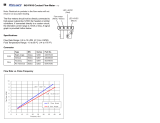
Table
7-1.
Drive
Roll
And
Wire
Guide
Kits
43

SECTION
1
-
SAFETY
INFORMATION
Figure
1-1.
Safety
Information
modl.1
2193
1
Safety
Alert
Symbol
2
Signal
Word
WARNING
means
possible
death
or
serious
injury
can
happen.
CAUTION
means
possible
minor
injury
or
equipment
damage
can
happen.
3
Statement
Of
Hazard
And
Result
4
Safety
Instructions
To
Avoid
Hazard
5
Hazard
Symbol
(If
Available)
6
Safety
Banner
Read
safety
blocks
for
each
sym
bol
shown.
7
NOTE
Special
instructions
for
best
oper
ation
not
related
to
safety.
SECTION
2-
SPECIFICATIONS
Table
2-1.
Wire
Feeder
Specification
Description
Type
Of
Input
Power
From
Welding
Power
Source
Single-Phase
24
Volts
AC,
10
Amperes,
50/60
Hertz.
(If
115
Volts
AC
Is
The
Only
Power
Available,
Use
Optional
Power
Supply
Adapter
Model
PSA-2.)
Maximum
Weld
Circuit
Rating
100
Volts,
750
Amperes,
100%
Duty
Cycle
Welding
Power
Source
Type
Constant
Voltage
(CV)
DC,
With
Contactor
Wire
Feed
Speed
Range
50
To
780
ipm
(1.3
To
19.8
mpm);
Standard
Motor
90
To
1400
ipm
(2.3
To
35.6
mpm);
High
Speed
Motor
Wire
Diameter
Range
.023
Thru
1/8
in
(0.6
To
3.2
mm)
Welding
Processes
Gas
Metal
Arc
(GMAW)
And
Flux
Cored
Arc
Welding
(FCAW)
Input
Power
Cord
Maximum
Height
With
4
ft
(1.2
m)
Post
10
ft
(3.1
m)
12
ft
(3.7
m)
Boom
16
ft
(4.9
m)
Boom
17
ft
(5.2
m)
21
ft
(6.4
m)
Weight
Net:
207
lb
(94
kg)
Ship:
318
lb
(144
kg)
Net:
280
lb
(127
kg)
Ship:
411
lb
(186
kg)
Vertical
Lift
Of
Boom
Horizontal
To
60
Above
Horizontal
Horizontal
To
600
Above
Horizontal
Read
all
safety
messages
throughout
this
manual.
Obey
all
safety
messages
to
avoid
injury.
Learn
the
meaning
of
WARNING
and
CAUTION.
2
a
WARNING
2
a
CAUTION
MOVING
PARTS
can
injure
Keep
away
from
moving
parts.~
L
:
ELECTRIC
SHOCK
can
kiIIJ~
Do
not
touch
live
electncal
parts
S
Keep
all
panels
and
covers
closed
Disconnect
input
power
before
when
operating.
inatalling
or
servicing.
/
5
,
READ
SAFETY
BLOCKS
at
start
of
I
Section
3-1
before
proceeding.
H
NOTE
~
Turn
Off
switch
when
using
high
frequency
-]
OM-1
584
Page
1

SECTION
3-INSTALLATION
3-1.
Equipment
Connection
Diagrams
A~
WARNING
CYLINDERS
can
explode
if
damaged.
Keep
cylinders
away
from
welding
and
other
electrical
circuits.
Never
touch
cylinder
with
welding
electrode.
Always
secure
cylinder
to
running
gear,
wall,
or
other
stationary
support.
ELECTRIC
SHOCK
can
kill.
Do
not
touch
live
electrical
parts.
Turn
Off
wire
feeder
and
welding
powersource,
and
disconnect
input
power
before
making
connections.
Stop
engine
on
welding
generator.
The
welding
wire,
drive
rolls,
drive
assembly,
and
all
metal
parts
touching
the
welding
wire
are
electrically
live
when
welding
or
feeding
wire
using
gun
trigger.
HOT
SURF
ACES
can
burn
skin.
Allow
gun
to
cool
before
touching.
Have
only
qualified
persons
install
this
unit.
wfwam9.1
2)93
2.
1
Welding
Power
Source
2
Remote
14
Connection
3
Negative
()
Weld
Output
Cable
4
Positive
(+)
Weld
Output
Cable
5
Workpiece
6
Voltage
Sensing
Clamp
7
Weld
Control
8
Boom
9
Gun
10
Swivel
11
Pipe
Post
And
Base
12
Gas
Hose
13
Gas
Supply
12
ST-i
53
176-A
10
9
Figure
3-1.
Typical
System
Connections
OM.1584
Page
2

3-2.
Installing
Swivel
Into
Pipe
Post
a
WARNING
RELEASE
OF
SPRING
PRESSURE
WITHOUT
BOOM
ATTACHED
can
cause
serious
personal
injury.
Do
not
remove
safety
collar
until
instructed
to
do
so.
FALLING
BOOM
can
cause
serious
personal
injury
and
equipment
damage.
Securely
mount
pipe
post
to
base
that
can
support
weight
of
unit
with
boom
in
horizontal
position.
Use
proper
equipment
for
lifting
swivel
and
boom
into
place.
5
4
1
Swingpak
Base
or
CBC
Cart
2
Pipe
Post With
Base
3
Steel
Bolt
Secure
as
shown
using
as
a
mini
mum
1/2
in
diameter
SAE
grade
5
steel
bolts.
4
Swivel
Assembly
Insert
into
pipe
post.
Lubricate
swivel.
5
Safety
Collar
Do
not
remove
until
instructed
to.
Tools
Needed:
~
3/4
in
ST-i
52
382
Figure
3-2.
Swivel
Installation
3-3.
Installing
Control
Box
Onto
Swivel
2
4
Tools
Needed:
3
cI::::::z:1===11
3/8
in
1
Weld
Control
2
Bracket
3
Screws
Bracket
and
screws
are
installed
onto
bottom
of
control
at
factory.
4
Swivel
Loosen
screws.
Place
control
on
swivel
and
slide
forward.
Tighten
screws.
ST-153
174
Figure
3-3.
Control
Box
Installation
OM-1
584
Page
3

3-4.
Installing
Boom
And
Reel
Support
3-5.
Installing
Wire
Guide
Extension
READ
SAFETY
BLOCKS
at
start
of
Section
3-2
before
proceeding.
1
Swivel
Plates
2
Yoke
Remove
hardware
from
swivel
plates
and
yoke.
3
Boom
Set
boom
into
swivel
as
shown.
4
Yoke
Pin
Install
pin
through
yoke.
Install
cot
ter
pin
and
spread
ends.
6
5
Bolt
7
Install
bolt,
tighten
hardware,
and
back
bolt
oft
one
half
turn.
6
Locking
Knob
Install
locking
knob
but
do
nottight
en.
7
Reel
Support
Install
reel
support.
Tools
Needed:
~
3/4,
3/8
in
Ref.
ST-153
170
Figure
3-4.
Boom
Installation
4
Tools
Needed:
3/8in
1
Wire
Guide
Fitting
2
Bolt
3
Monocoil
Liner
4
Wire
Guide
Extension
Tighten
bolt
to
secure
liner
in
wire
guide
fitting.
Do
not
overtighten
bolt
and
crush
liner.
Repeat
procedure
for
opposite
side.
ST-152
383
Figure
3-5.
Wire
Guide
Extension
Installation
OM-1584
Page
4

3-6.
Wire
Guide
And
Drive
Roll
Installation
READ
SAFETY
BLOCKS
at
start
of
Section
3-1
before
proceeding.
A.
Wire
Guide
Installation
When
changing
wire
size
or
type,
check
guide
size.
See
Table
7.1.
1
Drive
Rolls
Remove
drive
rolls
before
install
ing
wire
guides
(see
Figure
3-7).
2
Wire
Guide
Securing
Screws
Loosen
wire
guide
screws.
3
lnletWire
Guide
4
Intermediate
Wire
Guide
Insert
intermediate
guide
until
flange
on
guide
rests
against
cast
ing,
and
secure
with
guide
screw.
Install
drive
rolls
(see
Figure
3-7).
Repeat
procedure
for
opposite
side
of
wire
feeder.
Tools
Needed:
~==~
1
ST-137
391-F
I
ST-142
597-A
Figure
3-6.
Wire
Guide
Installation
B.
Drive
Roll
Installation
When
changing
wire
size
or
type,
check
drive
roll
size.
See
Table
7-1.
1
Spring
Shaft
Carrier
Close
spring
shaft
carrier.
2
Drive
Roll
Nut
3
Drive
Roll
Carrier
Turn
all
nuts
one
click
until
lobes
of
nut
line
up
with
lobes
of
drive
roll
carrier.
Open
spring
shaft
carrier.
4
Drive
Roll
Slide drive
rolls
onto
drive
roll
carri
ers.
Close
spring
shaft
carrier.
Turn
nut
one
click.
5
Drive
Assembly
Cover
Close
cover.
Repeat
procedure
for
opposite
side
of
wire
feeder.
ST-142
597-A
Figure
3-7.
Drive
Roll
Installation
OM-1
584
Page
5

3-7.
Welding
Gun
Connections
wfwami.i
2193
1
Drive
Assembly
Cover
2
Gun
Securing
Knob
3
Gun
Connector
Loosen
securing
knob.
Insert
gun
connector,
and
position
as
close
as
possible
to
drive
rolls
without
touching.
lighten
knob.
4
Gun
Trigger
Plug
5
Gun
Trigger
Receptacle
Insert
plug
into
free-hanging
re
ceptacle
and
tighten
threaded
col
lar.
6
Trigger
Cord
7
Trigger
Plug
8
Weld
Control
Trigger
Recep
tacle
Insert
plug
into
receptacle
and
tighten
threaded
collar.
Repeat
procedure
forgun
on
oppo
site
drive
assembly.
A~
WARNING
ELECTRIC
SHOCK
can
kill.
Do
not
touch
live
electrical
parts.
Turn
Off
wire
feeder
and
welding
power
source,
and
disconnect
input
power
before
inspecting
or
installing.
4
4
Figure
3-8.
Gun
And
Trigger
Lead
Connections
ST-i
53 072
/
Ref.
ST-153
172/
Ref.
ST-142
598-C
OM-1
584
Page
6

3-8.
Wire
Feed
Motor
And
Gas
Valve
Control
Connections
3-9.
14-Pin
Plug
Connection
Figure
3-10.
14-Pin
Plug
With
Pin
Information
1
Wire
Feed
Motor
And
Gas
Valve
Control
Receptacle
2
Plug
From
Boom
3
Cord
From
Boom
Insert
plug
from
boom
cord
it-ito
re
ceptacle
on
rear
of
control,
and
tighten
threaded
collar.
Repeat
procedure
for
opposite
side
of
weld
control.
Ref.
ST-142
598-c
Figure
3-9.
Boom
Connections
3
1
2
1
Plug
PLG1O
2
Keyway
3
Threaded
Collar
Connect
14-pin
plug
PLG1O
to
matching
receptacle
on
welding
powersource
as
follows:
align
key-
way,
insert
plug,
and
tighten
threaded
collar.
Pin
Information:
A,
B
Contact
closure
completes
the
24
volts
ac
contactor
control
circuit.
C
Command
signal:
+10
volts
dc.
D
Control
circuit
common.
E
Remote
power
source
voltage
command
signal
from
feeder(potentiometerwiperoro-1
0
volts
do
source);
0
to
+10
volts
dc.
F
Current
feedback;
0-10
volts
dc,
1
volt
per
100
amperes.
G
Circuit
common
for
24
volts
ac
circuit.
H
Voltage
feedback;
0-10
volts
dc,
1
volt
per
10
arc
volts.
The
remaining
pins
in
the
plug
are
not
used
by
the
feeder.
Ref.
ST-143 260-Al
Ref.
S-0512
OM-1
584
Page
7

3-10.
Shielding
Gas
And
Weld
Cable
Connections
a
WARNING
CYLINDERS
can
explode
it
damaged.
Keep
cylinders
away
from
welding
and
other
electrical
circuits.
Never
touch
cylinder
with
welding
electrode.
Always
secure
cylinder
to
running
gear,
wall,
or
other
stationary
support.
ELECTRIC
SHOCK
can
kill.
Do
not
touch
live
electrical
parts.
Turn
Off
wire
feederand
welding
powersource,
and
disconnect
input
power
before
inspecting
or
installing.
BUILDUP
OF
SHIELDING
GAS
can
harm
health
or
kill.
Shutoff
shielding
gas
supply
when
not
in
use.
The
weld
cables
and
shielding
gas
hoses
ex
tend
10
ft
(3m)
from
the
boom.
If
the
welding
power
source
or
gas
supply
are
further
from
the
boom,
extend
cables
and
hoses
as
follows:
1
Weld
Cables
2
Insulated
Sleeving
Bolt
together
weld
cables
from
welding
pow
ersource
and
boom.
Use
electrical
tape
and
insulated
sleeving
to
cover
connection.
3
Shielding
Gas
Extension
Hose
4
Boom
Shielding
Gas
Hose(s)
Connect
boom
shielding
gas
hoses
to
gas
supplies
or
extend
hoses.
The
hoses
from
the
boom
have
5/8-18
right-hand
threads.
5
Shielding
Gas
V
Adapter
Connect
single
end
fitting
of
V
adapter
to
gas
supply,
and
connect
boom
shielding
gas
hoses
to
fittings
on
V
end
of
adapter.
The
hoses
from
the
boom
have
5/8-18
right-hand
threads.
Figure
3-11.
Shielding
Gas
And
Weld
Cable
Connections
wam4.1
2/93
Tools
Needed:
~
5/8iri
Ref.
ST-153
175-B
OR
OM-1584
Page
8

3-11.
Voltage
Sensing
Lead
(Optional)
A
35
ft
(10.6
m)
voltage
sensing
lead
is
provided
with
several
options.
Connect
voltage
sensing
lead
to
workpiece
(see
Figure
3-1).
3-12.
Removing
Safety
Collar
And
Adjusting
Boom
a
WARNING
RELEASE
OF
SPRING
PRESSURE
FALLING
BOOM
can
cause
serious
WITHOUT
BOOM
ATTACHED
can
cause
serious
personal
injury.
personal
injury
and
Adjustment
rod
must
equipment
damage.
be
threaded
fully
through
Do
not
remove
safety
collar
until
instructed
to
do
so.
yoke.
1
Locking
Knob
lighten
knob
to
prevent
boom
movement.
Loosen
knob
to
allow
boom
movement.
Change
knob
position
to
limit
upward
movement.
Tools
Needed:
E
2
Increasing
Spring
Decreasing
Spring
Pressure
ForA
Pressure
ForA
I-ieavy
Gun
Light
Gun
move
safety
collar.
Boom
should
zontal
to
60
degrees
above
hori
balance
in
any
position
from
hori
2
Threaded
Rod
Pull
boom
down
slightly
and
re
zontal.
If
necessary,
adjust
boom
as
follows:
3
Jam
Nut
Loosen
jam
nut
and
turn
threaded
rod
until
boom
balances.
lighten
jam
nut.
Be
sure
several
full
vent
boom
falling.
threads
are
through
yoke
to
pro-
4
Yoke
Retain
safety
collar
for
use
in
dis
Z~
1-1/8
in
assembling
or
moving
boom.
Ret.
ST-142
599-B
/
Ref
ST-i
52
380-A
Figure
3-12.
Boom
Adjustments
3-13.
Welding
Wire
Installation
A.
Installation
Of
Spoo
I-Type
Wire
1
Retaining
Ring
2
Wire
Spool
3
3
Hub
Remove
retaining
ring
and
slide
spool
unto
hub.
1
4
HubPin
Turn
spool
until
hub
pin
fits
in
spool.
Reinstall
retaining
ring.
Repeat
procedure
for
installing
spool-type
wire
on
opposite
side
of
wire
feeder.
E
ST-i
53
171
Figure
3-13.
Installation
Of
Spool-Type
Wire
OM-1
584
Page
9

B.
Installation
Of
Optional
Wire
Reel
And
Reel
Type
Wire
C.
Adjusting
Hub
Tension
Figure
3-14.
Installation
Of
Optional
Wire
Reel
And
Reel
Type
Wire
8
5
4
1
Retaining
Ring
2
Spanner
Nut
3
Lock
4
Wire
Retainer
5
Wire
Reel
6
Hub
7
Hub
Pin
8
Reel
Support
Remove
retaining
ring.
Pull
lock
and
turn.
Remove
spanner
nut,
wire
retainer,
and
wire
reel
from
hub.
Lay
wire
reel
assembly
on
flat
sur
face,
and
install
wire
as
shown.
Tighten
spanner
nut
until
lock
is
in
position
over
hole
in
wire
retainer.
Pull
lock
and
turn
to
insert
locking
pin
into
wire
retainer.
Slide
wire
reel
assembly
onto
hub,
and
turn
assembly
until
hub
pin
is
seated
in
hole
in
reel.
Reinstall
re
taining
ring.
ST-i
43478-A
/
sT-i
52
463
~T)
/cDDD~\
Wire
Installation
Tum
Off
wire
feeder
and
welding
power
source.
1
Hex
Nut
2
Spool
Grasp
spool
in
one
hand
and
turn
while
using
a
wrench
to
adjust
hex
nut.
When
a
slight
force
is
needed
to
turn
spool,
tension
is
set.
Repeat
procedure
to
adjust
hub
tension
on
opposite
side
of
wire
feeder.
Tools
Needed:
~
5/8in
5T-153
i73
Figure
3-15.
Adjusting
Hub
Tension
OM-1584
Page
10

3-14.
Motor
Start
Control
a
WARNING
ELECTRIC
SHOCK
can
kill.
Do
not
touch
live
electrical
parts.
Turn
Off
wire
feederand
welding
powersource,
and
disconnect
input
power
before
inspectIng
or
installing.
Figure
3-16.
Motor
Start
Control
On
Motor
Control
Board
PCi
STATIC
ELECTRICITY
can
damage
parts
on
circuit
boards.
Put
on
grounded
wrist
strap
BEFORE
handling
boards
or
parts.
wfwaml.1
2193
To
change
wire
feed
starting
speed
proceed
as
follows:
Turn
Off
wire
feeder
and
welding
power
source.
Remove
wrapper.
1
Front
Panel
Front
panel
shown
open
for
illus
tration
purposes.
2
Motor
Board
PCi
3
Motor
Start
Control
Poten
tiometer
R70
Turn
potentiometer
clockwise
to
in
crease
time
It
takes
the
motor
to
ramp
up
to
speed.
Remove
protec
tive
white
rubber
cap
before
mak
ing
adjustment.
Adjust
potentiome
ter
R70
using
a
small
nonconduc
tive
screwdriver.
Close
and
secure
front
panel,
and
reinstall
wrapper.
Tools
Needed:
non-conductive
cII:1:::::l=::=U
1/4
in
Ref.
$T-142
710-A
/
SB-146
862-0
OM-i
584
Page
11

3-15.
DIP
Switches
Options
A~
WARNING
ELECTRIC
SHOCK
can
kill.
Do
not
touch
live
electrical
parts.
Turn
Off
wire
feederand
welding
powersource,
and
disconnect
input
power
before
inspecting
or
installing.
STATIC
ELECTRICITY
can
damage
parts
on
circuit
boards.
Put
on
grounded
wrist
strap
BEFORE
handling
boards
or
parts.
wfwaml.1
2/93
Figure
3-17.
Spot
Time
DIP
Switch
Si
Ref.
ST-142
710-A/
SA-146
866-B
A.
Spot
Time
DIP
Switch
Si
Change
DIP
switch
position
if
a
dif
ferent
range
of
Spot
Time
is
de
sired.
Turn
Off
wire
feeder
and
welding
power
source.
Rernove
wrapper.
1
Front
Panel
Remove
screw
from
upper
left
cor
ner,
and
open
hinged
front
panel.
2
4-In-i
Board
PC3O
3
Spot
Time
DIP
Switch
Si
Place
switch
(on
either
or
both
PC3O
boards)
in
desired
position:
Long
Time
for
0-5
seconds,
and
Short
Time
for
0-2.5
seconds
(see
Figure
4-11
for
control
operation).
Close
and
secure
front
panel,
and
reinstall
wrapper.
Tools
Needed:
non-conductive
c::::::::J:~n
1/4
in
OM-1
584
Page
12
/