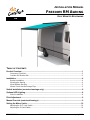
Carefree Freedom Roof Mount Installation guide
- Category
- Flat panel accessories
- Type
- Installation guide
Carefree Freedom Roof Mount is a state-of-the-art lateral arm awning that provides shade and protection from the elements. It features a fully retractable and self-storing design with a sealed awning motor that operates on standard 12VDC power. The awning's strong aluminum construction and polyester paint finish ensure durability, while its streamlined styling blends seamlessly with your RV's sidewall. Enjoy customizable shade coverage with the awning's variable extension and adjustable pitch.
Carefree Freedom Roof Mount is a state-of-the-art lateral arm awning that provides shade and protection from the elements. It features a fully retractable and self-storing design with a sealed awning motor that operates on standard 12VDC power. The awning's strong aluminum construction and polyester paint finish ensure durability, while its streamlined styling blends seamlessly with your RV's sidewall. Enjoy customizable shade coverage with the awning's variable extension and adjustable pitch.


-
 1
1
-
 2
2
-
 3
3
-
 4
4
-
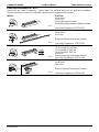 5
5
-
 6
6
-
 7
7
-
 8
8
-
 9
9
-
 10
10
-
 11
11
-
 12
12


Carefree Freedom Roof Mount Installation guide
- Category
- Flat panel accessories
- Type
- Installation guide
Carefree Freedom Roof Mount is a state-of-the-art lateral arm awning that provides shade and protection from the elements. It features a fully retractable and self-storing design with a sealed awning motor that operates on standard 12VDC power. The awning's strong aluminum construction and polyester paint finish ensure durability, while its streamlined styling blends seamlessly with your RV's sidewall. Enjoy customizable shade coverage with the awning's variable extension and adjustable pitch.
Ask a question and I''ll find the answer in the document
Finding information in a document is now easier with AI
Related papers
-
Carefree Freedom Roof Mount User manual
-
-
-
-
-
-
-
-
-
Other documents
-
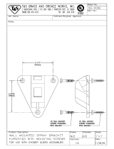 T & S Brass & Bronze Works SQ-0092 Datasheet
-
Dometic AE Systems 3105944.007-10in Air Foil Kit Installation guide
-
 Carefree of Colorado FREEDOM RM AWNING Installation guide
-
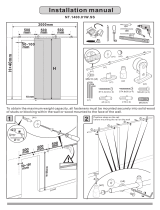 Stainless Glide NT140001WSS Installation guide
-
AWNTECH ME7-W Operating instructions
-
 Stainless Glide NT140004WSS Installation guide
-
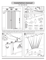 Stainless Glide NT140002WSS Installation guide
-
-
-


