
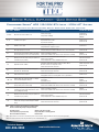
Technical Support
800-334-3393
www.bradfordwhite.com
Error Code Definition Service Action Possible Parts Needed
No Code No power to the unit or switch is off
Check power supply
Verify 24 volts at display
1) Transformer
2) Control board
3) Display
9, 22 Low flame sense signal
Check microamps
Inspect flame sensor & wire
Inspect burner for debris
1) Flame sensor
2) Control board
49 24 VAC too low or high
Verify proper supply voltage
Verify transformer output is 22-27 Vac
1) Transformer
53 AC voltage input phase reversed
Check for proper grounding/polarity
Verify the wiring connections J4-10 and J8-2 are connected together
1) Control board
62
Fan speed not proved (if valve remains out of range,
this hold will change to lockout 123, defined below)
Check for vent/intake restriction
Check blower modulation wire harness at J2 connection for continuity
1) Blower
2) Control board
67
Normally closed vent safety circuit opened (blocked
vent switch in open position)
Check if blocked vent switch at draft hood is open
Check for vent restriction
Verify adequate draft--confirm downdraft not present
1) Blocked vent switch
2) Control board
80 High limit overheat condition
Verify water temperature inside the tank is not above 207°F
Measure resistance of temperature sensor
Check wire harness and connections
1) Water temperature sensor
2) Control board
93
Water temperature sensor fault (this hold appears
after alert 172, defined below)
Measure resistance of water temperature sensor
Check wire harness and connections
1) Water temperature sensor
2) Control board
105 Flame detected out of sequence
Check flame sensor/wire
Verify ignition cable is not crossing flame sense or ground wires
1) Flame sensor
109, 110
Ignition failure after 4 trials (hold 110 is on display,
stored as 109 in Diagnostic History)
Verify ignition sequence
Clean igniter
Clean flame sensor
1) Burner
2) Igniter
3) Control board
122
Light off rate proving failed
(fan speed not proved - hard lockout)
Check for vent/intake restriction
Check blower modulation wire harness at J2 connection for continuity
1) Blower
2) Control board
123
Fan speed not proved - purge rate proving failed (this
lockout appears after hold 62 defined above, and is
stored in Diagnostic History)
Check for vent/intake restriction
Check blower modulation wire harness at J2 connection for continuity
1) Blower
2) Control board
137
Normally closed vent safety circuit opened (blocked
vent switch in open position)
Check if blocked vent switch at draft hood is open
Check for vent restriction
Verify adequate draft--confirm downdraft not present
1) Blocked vent switch
2) Control board
172
Water temperature sensor resistance invalid (if value
remains out of range, hold 93 is displayed, defined
above)
Measure resistance of water temperature sensor
Check wire harness and connections
1) Water temperature sensor
2) Control board
Commander Series
®
UCG 125-399K BTU Input - ICON HD
®
System
All BTU Inputs with Battleship Grey Display: Serial Date Code “XC” and Later*
NOTE: If there is no display, check primary/secondary voltage
Before troubleshooting, always verify the following:
Gas inlet pressure All wire connections are tight
Static to dynamic gas pressure drop No grounded wires or missing grounds
No vent and intake restrictions No water leaks
*March 2021 and later. If serial is at or near this date please contact Technical Support at 800-334-3393 to verify control generation
Always check the manufacture date using the Warranty Center at Bradfordwhite.com
QSG-UCG-125-399K-iHD-0321
-
 1
1

Bradford White UCG-80H-125-3N Quick Service Guide
- Type
- Quick Service Guide
- This manual is also suitable for
Ask a question and I''ll find the answer in the document
Finding information in a document is now easier with AI
Related papers
-
Bradford White EF-120T-400-3N Quick Service Guide
-
Bradford White EF-100T-250E-3N Quick Service Guide
-
-
Bradford White UCG-100H-199-3N User manual
-
-
-
-
-
-
Other documents
-
Carrier Series 100 Troubleshooting guide
-
-
Bryant 355BAV Troubleshooting guide
-
American Water Heater (A)BCG38T500-8P User manual
-
Igloo In-Home Display User manual
-
 GOODMAN GMEC96 User guide
-
PVI Industries POWER VT PLUS Installation guide
-
-
Sears PG8MAA048110AAJA Installation guide
-
Sears 58STX09010016 Installation guide
