Page is loading ...

Mounting
• To avoid corrosion to connecting wires and terminals, mount in a dry and protected location
if possible. Avoid locations directly above the battery banks.
Electrical Connections
• The wiring diagrams illustrated on the back page represent common installations and are not meant to
beaguideforwiringaspecicvehicle.
• The 7611 ACR is not intended to carry starting currents. Use a battery switching system with a
combine batteries/parallel function if batteries may need to be combined for emergency starting.
Caution: Disconnect battery connections before beginning the installation.
Use the Wire Size and Fuse Ratings chart on page 2 to select the appropriate wire sizes to prevent
overheating the ACR.
Voltage Sensing
• The 7611 ACR will sense charging sources available on either battery bank.
Minimum connections for operation:
• Connect one battery bank to stud terminal A.
• Connect the other battery bank to stud terminal B.
• Connect the quick connect terminal marked Ground to the DC system ground through
aoneampin-linefusetopreventfaultcurrentsfromowinginthiswire.
Optional connections:
1. Auxiliary Battery Priority
The7611ACRcanbeconguredtoallowbatteriestoremain“paralleled”downtoadecreased
“OpenLow”voltageof12.25/24.5VDCifdesired.Enablethisfeatureifyouneedtoaccesssomeofyour
enginestartbattery’sstoredenergyforaccessoryloads.Thefeaturecanbeconguredfortemporary
use while the ignition is on, or permanently. Wiring permanently allows this device to also be used as a
LowVoltageDisconnect(LVD)topreventaccidentalandpotentiallydamagingover-dischargeof
accessory batteries by disconnecting loads.
To enable temporary voltage override:
• Connect a wire from the quick connect terminal marked Aux. Battery Priority through an
appropriatelysizedin-linefuse(onetotenamp)toaterminalorwirerunningfromtheignitionswitch
thatis+12/24VDCwhiletheignitionison,andat0VDCwhenignitionisoff.
To enable permanent voltage override:
• Connect a wire from the quick connect terminal marked Aux. Battery Priority through an
appropriatelysizedin-linefuse(onetotenamp)toa+12/24VDCsource
2. Remote indicator lamp –mimics“COMBINED”LEDonunit.
Appropriate12/24VLEDsincludeBlueSeaSystemsPNs8033(amber),8171(red),or8172(green).
To connect a remote LED indicator:
• ConnecttheredwireoftheLEDtoa12/24Vpositivesourcethroughaonetotwoampinlinefuse.
• ConnecttheyellowwireoftheLEDtothequickconnectterminalmarkedLED.
Open/Close Cycling
• Ifyourelectricalsystemisconguredwithachargingsourcethatcannotsupplythefullloadcurrent
beingdrawnfromthereceivingbatteries,anopen/closecyclingprocesscanoccur.Ifthiscycling
continues, the second battery bank could eventually discharge even though a charge source
is present.
BatteryLink
®
ACR
Automatic Charging Relay
with Auxiliary Battery Priority
980011740Rev.003
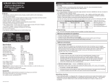
Features
• Automatically combines batteries during charging and isolates batteries when discharging
• OptionalAuxiliaryBatteryPriorityconnectionsharesthealternatorchargewiththeAuxiliarybattery
longer allowing the use of the auxiliary loads for an extended period of time when the engine is running
•120AContinuousratingtosupporthighoutputalternators
•Onetenthofthevoltagedropofabatteryisolatorresultsinmorefullychargedbatteries
• Dual sensing to manage multiple charge sources
• Robust, fully sealed assembly for reliability in environments with vibration and moisture
• Clip-on cover insulates terminal connections
•Easytoinstall
•IntegratedLEDindicatesACRstatus(LEDisONwhenbatteriesarecombined)
•OptionalremoteLEDoutputforindicationofACRstatus
Specications 12VDC 24VDC
ContinuousRating 120A 120A
IntermittentRating(5min.) 210A 210A
MaximumCableSize 1/0AWG 1/0AWG
TerminalStudSize 3/8"-16(M10) 3/8"-16(M10)
MaximumTorque 140in-lbs 140in-lbs
MaleQuickConnectTerminals 1/4″x.032″ 1/4″x.032″
Relay Contact Position
Combine (30sec.) 13.6VDC 27.2VDC
Combine (2min.) 13.0VDC 26.0VDC
OpenLow (30sec.) 12.75VDC 25.5VDC
Open-OverVoltageLockout 16.0VDC 32.0VDC
Auxiliary Battery Priority (optionalfeature)
OpenLow (30sec.) 12.25VDC 24.5VDC
Regulatory
E marked for Ignition Protection, Meets ISO 8846,
UL 1500 and SAE J1171 external ignition
protection requirements
Rated IP67----protected against immersion up to
1meterfor30minutes
Guarantee
Blue Sea Systems stands behind its products for
as long as you own them. Find detailed
information at www.bluesea.com/about.
Forcustomerservice,call800-222-7617.
PN 7611
MarineElectricalProd
ucts
Installation Instructions
LED Status Chart
LED Relay Status
ON Closed Batteries Combined
OFF Open BatteriesIsolated

980011740Rev.003
425SequoiaDrive
Bellingham, WA 98226 USA
p 360.738.8230
p 800.222.7617 USA and Canada
f360.734.4195
www.bluesea.com
Recommended Installation Diagram
* This installation diagram shows a typical application only. Your application may differ.
For further information, please go to www.bluesea.com and navigate to
Resources/Application Briefs and Technical Briefs.
*BecausetheBatteryLink™ ACR is Dual Sensing, terminals A and B are interchangeable.
ACR function will not be affected by reversal of the starting and house batteries versus
the diagram.
*ItisrecommendedthattheACRbeconnecteddirectlytoyourbatterypositiveterminals
through appropriately sized fuses. Connecting in a different location such as a battery
switch may affect accuracy because of voltage drop along current carrying conductors.
*Ifyouarenotknowledgeableaboutelectricalsystems,pleaseconsultanelectrical
professional for help with installation.
LEGEND
Positive
Negative
Optional
Fuse
1A
16 AWG
start
run
accessory
off
Start Key Switch
Optional
Remote LED
Auxiliary Battery Priority
Optional Connection
See Wire Size and Fuse Rating Chart for
connections of Terminals A and B.
NOTE: To determine wire sizes and fuse
ratings for all other wires illustrated
please visit the Circuit Wizard at
circuitwizard.bluesea.com
1-10A
16 AWG
16 AWG
Auxiliary
Battery
Start
Solenoid
Start
Battery
850 CCA* Maximum
* Cold Cranking Amperes
1-2A
Dimension Drawings
Wire Size and Fuse Ratings
*Largerwiresizesmayberequiredtominimizevoltagedropinlongwireruns.
For more information please use the Circuit Wizard at www.circuitwizard.bluesea.com
Wire Size and Fuse Rating Chart (Metric)
Charging Amps Minimum Wire Size* Fuse Rating
≤50 10 mm
²
75-80A
≤70 16 mm
²
80-90A
≤90 25 mm
²
125-130A
≤110 35 mm
²
150A
≤120 50 mm
²
150-175A
Wire Size and Fuse Rating Chart (AWG)
Charging Amps Minimum Wire Size* Fuse Rating
≤60 #6 75-90A
≤80 #4 100-125A
≤100 #2 150A
≤120 #1 175A
/