Page is loading ...

Can be congured to be used as one of the following battery saving products
Timer Disconnect
• 12V signal triggers relay to connect battery power to devices
• When signal is removed the timer is activated and will disconnect devices after a preset time
• Timer ranges from 15 minutes to 4 hours
Low Voltage Disconnect
• 12V signal triggers relay to connect battery power to devices
• After 12V signal is removed, ATD senses low battery voltage and automatically
disconnects devices
• Low voltage setting can be used in conjunction with Timer Disconnect. Low voltage will
disconnect devices prior to preset time to preserve battery power
Automatic Charging Relay
• Automatically combines two batteries when charging, and isolates them when discharging
• Single side sensing design only monitors the voltage of the start battery
• Ideal for auxiliary batteries that are AGM or signicantly larger than the start battery
Solenoid
• 12V signal will connect or disconnect relay without any time delay
Installation Instructions
ATD Automatic Timer Disconnect
7615
DC
AC
Before beginning electrical installation, disconnect all AC and DC power sources.
Do not service equipment that has been automatically disconnected by the ATD without rst permanently
removing power from the equipment by a means other than the ATD.
WARNING
CAUTION
If you are not knowledgeable about electrical systems, consult an electrical professional.
To avoid corrosion to connecting wires and terminals, mount in a dry and protected location if possible.
Avoid locations directly above the battery banks.
The ATD is not intended to carry engine starting currents. If the ATD is used as a disconnect, do not wire it in
line with the starting circuit. If the ATD is used as an ACR, do not use it to combine batteries for emergency
starting. Use a battery switching system with a combine batteries/parallel function if batteries may need to be
combined for emergency starting.
980025450 Rev.002
Specications
Nominal Voltage 12V DC
Input Voltage Range 9.5–16V
Continuous Rating 120A
Intermittent Rating: 5 min. 210A
(Combine) Amperage Operating Current 175mA
(Open) Amperage Operating Current 4mA
Cable Size to Meet Current Ratings 1 AWG (50mm²)
Maximum Cable Size 1/0 AWG (50mm²)
Terminal Stud Size 3/8"-16 (M10)
Terminal Stud Torque 140 in-lb (15.82 Nm)
Time Range 15 Minutes – 4 Hours
Charge Sense ON
Connected (3 sec) 13.0V or greater
Timing (10 sec) 12.75V or lower
Low Voltage
Disconnected (10 sec) Battery Voltage < Disconnect Voltage
Over Voltage
Disconnected (5 sec) 16.0V or greater
Regulatory
CE marked for ignition protection. Meets ISO 8846 and SAE J1171 external ignition
protection requirements
IP67 - protected against immersion up to 1 meter for 30 minutes
Guarantee
Blue Sea Systems stands behind its products for as long as you own them.
Find detailed information at www.bluesea.com/about.
For customer service, call 800-222-7617.
Refers to a potentially hazardous situation which, if not avoided, may result in minor or moderate injury.
Refers to a potentially hazardous situation which, if not avoided, may result in death or serious injury.
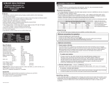
Minimum connections for operation:
- Connect the primary/starting battery to the stud marked BATT.
- Connect the loads to be disconnected to the stud marked LOAD (or connect the secondary/house
battery for ACR applications).
- Connect the quick connect terminal marked GND (ground) to the DC system ground.
- Start key / Ignition: Used to trigger the ATD to connect. Wire the quick connect terminal marked "Start
Key" through a 1-10A fuse to the accessory position of your ignition switch to enable the ATD to close
when the ignition is on.
NOTE: The Start key / Ignition connection is optional if and only if the "Charge Sense" DIP switch is enabled, in
which case the ATD will be triggered to connect if battery voltage is above 13.0V for 3 seconds.
Optional Connection:
Remote Indicator LED - mirrors the status LED on the ATD
- Appropriate 12V LEDs include Blue Sea Systems PNs 8033 (amber), 8171 (red), or 8172 (green).
- To install a remote LED indicator, connect the positive (red) wire of the LED to a 12V positive source
through a 1-10A inline fuse, and connect the negative (yellow) wire to the quick connect terminal on the
ATD marked "LED".
Dimensioned Drawings

Setup
There are three behaviors that can be customized for the ATD by setting all six DIP switches on the
back side of the device. These behaviors can work together or independently.
Wire Size and Fuse Ratings
Example Settings
Dip Switch Settings Time Voltage
Charge
Sense
Mode Application
Disabled Disabled Off Solenoid Remote Battery Switch
30 min Disabled Off Timing Only Ignition Controlled - Delayed off
Disabled 11.5V Off LVD Only Ignition Controlled - Load shedding
15 min 11.5V Off Timing & LVD
Ignition Controlled -
Delayed off with low voltage override
Disabled Disabled On ACR
Automatic Sensing - Charging a second
battery with single alternator
1 hr 11.0V On
Timing, LVD, &
Charge Sense
Automatic Sensing -
Delayed off with low voltage override
2. Set Disconnect Voltage
Low battery voltage that will
trigger power disconnect from
devices.
1. Set Disconnect Time
Amount of time delay before power
is disconnected from devices.
3. Set Charge Sense
Allows ATD to be either manually
activated by a 12V signal or
automatically activated by
sensing a charging source
(i.e. engine alternator).
Note: Use a small at blade
screwdriver or other suitable tool
to set switches. DIP switch settings
are checked by the device once per
second. If settings are changed while
the device is in timing mode, the
timer will be reset to the new value.
START
ON
OFF
BATTERY
COMMON BUS BAR/CHASSIS
16 AWG
GROUND
IGNITION SWITCH
2 AMP
FUSE
2 AMP
FUSE
OPTIONAL
REMOTE
LED
OPTIONAL START KEY*
16 AWG
16 AWG
NON-CRITICAL LOADS
Dip Switches 1-3
Dip Switch Settings Time
0 sec
5 sec
15 min
30 min
1 hr
1.5 hr
2 hr
4 hr
Dip Switches 4-5
Dip Switch Settings Volts
Disabled
11.0V
11.5V
12.0V
Dip Switch 6
Dip Switch Settings Charge
Sense
Off
On
Timer, Solenoid, or Low Voltage Disconnect
Use the wiring sizing chart below to select the appropriate wire sizes to prevent overheating the ATD.
Consult an ABYC certied electrician for proper fuse placement and sizing.
* For Disconnect mode, this is dened as the maximum continuous amperage being drawn through the ATD by the
loads. For ACR mode, this is the charging amperage of the power source (i.e. engine alternator).
** Larger wire sizes may be required to minimize voltage drop in long wire runs. For more information please use the
Circuit Wizard at www.circuitwizard.bluesea.com
Note: Because the ATD is single sensing
the battery must be attached to the stud
labeled “BATT” and the devices to be
disconnected must be attached to the
stud labeled “LOAD”. Reversal of these
connections will render charge sense
functionality non-operational.
Legend
DC Positive DC Negative
2 AMP
FUSE
OPTIONAL
REMOTE
LED
GROUND
GROUND
COMMON BUS BAR/CHASSIS
START BATTER
YH
OUSE BATTERY
ENGINE
ACCESSORIES
16 AWG
16 AWG
Optional Connection
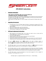
Automatic Charging Relay
Note: Because the ATD is single sens-
ing, the battery connected to the charg-
ing source must be attached to the stud
labeled “BATT”. Reversal of the starting
and house batteries will create undesirable
results.
It is recommended that the ATD be con-
nected directly to your battery positive
terminals through appropriately sized fuses.
Connecting in a different location such as a
battery switch may affect accuracy because
of voltage drop along current carrying
conductors.
The Start Key terminal is an optional con-
nection when in ACR mode. If connected
the ATD will connect anytime an ignition
signal is sensed. Once ignition signal is
removed the ATD will go back to voltage
sensing. If desired, wire the same as the
diagram below.
Installation Diagrams
425 Sequoia Drive
Bellingham, WA 98226 USA
p 360.738.8230
www.bluesea.com
DIP Switches
Wire Size and Fuse Rating Chart (Metric)
Continous Amps* Minimum Wire Size** Fuse Rating
≤50 10 mm
²
75-80A
≤70 16 mm
²
80-90A
≤90 25 mm
²
125-130A
≤110 35 mm
²
150A
≤120 50 mm
²
150-175A
Wire Size and Fuse Rating Chart (AWG)
Continuous Amps* Minimum Wire Size** Fuse Rating
≤60 #6 75-90A
≤80 #4 100-125A
≤100 #2 150A
≤120 #1 175A
These installation diagrams show typical applications only.
Your application may differ.
* Start Key connection is optional only if "Charge Sense" setting
is enabled, to allow the ATD to connect when it senses battery
voltage above 13.0V for 3 seconds.
/