STEEL BASEMENT DOORS PRODUCTS/INSTALLATION
CELLAR DOOR
FOR NEW
CONSTRUCTION
AND
EXISTING
FLAT
FOUNDATIONS
REPLACEMENT
DOOR
FOR
SLOPING
FOUNDATIONS

1
CD-MODEL–
FOR EXISTING FLAT FOUNDATIONS
AND NEW CONSTRUCTION
HEIGHT
LENGTH
57"
24
1
/2"
WIDTH
45"
HEIGHT
LENGTH
54"
30"
WIDTH
45"
HEIGHT
LENGTH
63"
22"
WIDTH
49"
HEIGHT
LENGTH
71"
19
1
/2"
WIDTH
53"
HEIGHT
LENGTH
42
1
/
2
"
51"
WIDTH
49"
MODEL CD-0
MODEL CD-1
MODEL CD-2
MODEL CD-SL
MODEL CD-3
NOTE: Dimensions shown are outside frame dimensions.
OUTSIDE FRAME DIMENSIONS CD-3 WITH CX EXTENSIONS
MODEL CD-SL CD-0 CD-1 CD-2 CD-3 CX-6" CX-12" CX-18" CX-24" CX-30
LENGTH 42
1
/
2
" 54" 57" 63" 71" 77" 83" 89" 95" 101"
WIDTH 49" 45" 45" 49" 53" 53" 53" 53” 53" 53"
HEIGHT 51" 30" 24
1
/
2
” 22" 19
1
/
2
" 21" 21" 21" 21" 21"
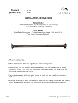
HOW TO SELECT DOOR WITH SIDES
1. Measure dimensions A, B, C, D and K.
2. Select length at least 2” longer than
“A” and no longer than “B”.
3. Select width at least 4” wider than “C”
and no wider than “D”.
4. Check to make sure the height of the
model selected is greater than “K”.
The “K” dimension is the distance from
the top of the foundation to the top of
basement door opening, not the
height of you
r ol
d door.
When using a CD door for remodeling,
K dimension is not the height of your
wooden door.
*NOTE: Only CD-3 can be extended. If standard sizes and extensions do not fulfill the foundation
requirements please call 860-628-0000 for guidance.
K

MODEL WIDTH LENGTH WITH 6" WITH 12" WITH 18"
EXTENSION EXTENSION EXTENSION
RD-0 44 1/2" 48"
53" - 55" 59" - 61"
NA
RD-1 44 1/2" 62"
67" - 69" 73" - 75"
NA
RD-2 48 1/2" 66 1/2"
71" - 73" 77" - 79"
NA
RD-3 52 1/2" 73 1/2"
78" - 80" 84" - 86" 90" - 92"
OUTSIDE FRAME DIMENSIONS EXTENSION HEADERS ARE NOT INCLUDED
IN DOORS — ORDER SEPARATELY
2
RD Model
REPLACEMENT DOORS
FOR SLOPING FOUNDATIONS
IF LONGER
LENGTHS
ARE
REQUIRED,
ORDER FLAT
STEEL FROM
THE PLANT
LENGTH
62"
WIDTH
44
1
/
2
"
A
B
C
D
LENGTH
73
1
/
2
"
WIDTH
52
1
/
2
"
LENGTH
66
1
/
2
"
WIDTH
48
1
/2
"
LENGTH
48"
WIDTH
44
1
/
2
"
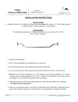
HOW TO SELECT A DOOR WITHOUT METAL SIDES
1. Measure dimensions A, B, C and D.
2. Select length at least 2” longer than “A” and
no longer than “B”.
3. Select width at least 4” wider than “C” and
no wider than “D”.
MODEL RD-0
MODEL RD-1
MODEL RD-3
MODEL RD-2
NOTE: Dimensions shown are outside frame dimensions.
Order X1-6 for RD-1, X2-6 for RD-2 X3 for RD-3, etc.
X1-6
X1-6
X3-6
X1-12
X1-12
X3-12 X3-18
96" - 98"
X3-24

CATCH
ROD
CATCH
SLIDE
DO NOT ALLOW CATCH ROD TO
RUB ON THE HEADER AREA
NOTED HERE
BEND CATCH ROD
AT THIS POINT
IN DIRECTION
OF ARROWS
HEADER
3
CD INSTALLATION
STEP 1–ASSEMBLE FRAME STEP 2–ATTACH FRAME TO HOUSE
STEP 3– SLIDE ON DOOR PANELS STEP 4–INSTALL CATCH RODS
STEP 5– ALIGN AND ADJUST DOOR PANELS STEP 6–DRILL AND ATTACH FRAME
Use
1
/4
” bolts and nuts from hardware package. Bolt heads
must face the outside of the door frame. Nuts on the inside.
NOTE: The sill bends toward the house.
Align frame on foundation and attach only at center hole
in header.
Align the door with the upper and lower pins. Slide door
bushing onto door pi
ns.
Install catch rods into catch slides. Adjust rods by bending
them slightly. Do not allow them to rub on the header.
Adjust frame and doors by moving them from side to
side until you find the point at which the doors will open
and close without binding.
Use prepunched holes in sides and sill as a guide, drill
holes onto the foundation 1
3
/4
” deep using a
1
/4
” masonry
bit. Install plastic rawl plugs and fasten with 1
1
/2
” screws
until snug. Check door alignment again. Over tighteni
ng
will cause misalignment.
Bolt Head

MODEL CD-3 WITH EXTENSIONS
HINGE
PLATE
INSERT
HERE
TORSION
SPRING
INSERT
HERE
4
CD INSTALLATION (con't.)
STEP 7–INSTALL TORSION SPRINGS STEP 8–CAULK FRAME
Insert torsion springs by sliding the spring under the hinge
plate. Point faces downward and inserts into spr ing clip. If new
cement, allow to set before inserting springs. Models CD-1 and
CD-2 have 2 torsion springs. Model CD-3 has 4 torsion springs.
To avoid leakage caulk around frame and promptly paint
the door using alkyd base outdoor metal enamel paint.
NOTE: Do not cement over flanges.

CATCH
ROD
DOOR HEADER
DOOR HEADER
HEADER ANGLE
CENTER HOLE
BOLT HEADS
BOLT HEAD
CATCH
SLIDE
DO NOT ALLOW CATCH ROD TO
RUB ON THE HEADER AREA
NOTED HERE
BEND CATCH ROD
AT THIS POINT
IN DIRECTION
OF ARROWS
HEADER
5
RD INSTALLATION
STEP 1–ASSEMBLE FRAME STEP 2– ATTACH DOOR TO FOUNDATION
STEP 3–SLIDE ON DOOR PANELS STEP 4–INSTALL CATCH RODS
STEP 5–ALIGN AND ADJUST DOOR PANELS STEP 6–DRILL AND ATTACH FRAME
Use
1
/4” bolts and nuts from hardware package. Bolt heads must
face the outside of the door frame.
NOTE: The sill bends towards the house
Align the door with the upper and lower pins, slide door bushing
onto door pins.
Adjust frame and doors by moving them from side to side until
you find the point at which the door will open and close without
binding.
Attach header angle to door header, bolting at center hole
only. Fasten header angle to house using all 3 holes. Drill
and attach 2 remaining holes in header angle to foundation
using plastic rawlplugs and screws provided.
Install catch rods into catch slides. Adjust rods by bending
them slightly–Do not allow them to rub on the header.
Using prepunched holes in side rails and sill as a guide,
drill holes into the foundati
on 1
3
/4
” deep-using a
1
/4
”
masonry bit. Install plastic rawl plugs and fasten with 1
1
/2
”
screws until snug. Check door alignment again; over-
tightening will cause misalignment.

HINGE
PLATE
INSERT
HERE
TORSION
SPRING
INSERT
HERE
6
RD INSTALLATION (conʼt)
STEP 7–INSTALL TORSION SPRINGS STEP 8–CAULK FRAME
Insert torsion springs by sliding the spring under the hinge
plate–point faces downward and inserts into spring clip. If new
cement–allow to set before inserting springs.
To avoid leakage, caulk around frame and promptly paint
the door using alkyd based outdoor metal enamel
paint.
NOTE: Do not cement over flanges.
ASSEMBLE RD MODEL ATTACH EXTENSION HEADER
BOLT EXTENSION AND DOOR HEADER CAULK FRAME
Assemble door by repeating Step 1, however do not repeat
Step 2. Instead fasten frame at the sill-using the center hole.
Leave space at top of frame for extension header which should
overlap door frame.
Drill a 1/4” hole through the extension header and the door header.
Bolt the two headers together with
1
/4
” nuts and bolts. The extension
header should be fastened in three places.
NOTE: When using extension header, discard header angle that
came with your door. 3-
1
/4
” nuts and bolts required for attachment.
Line the extension header up with the door frame fasten it to
the house
To avoid leakage Caulk around frame and promptly paint
the door using alkyd based outdoor enamel paint.
NOTE: Do not cement over flanges.
MODEL RD WITH EXTENSIONS

F
H
G
84"
3"
7
FOUNDATION PLATES
USES
SPECIAL SIDES
Dimensions
H F G
3” 5” 84”
3” 8” 84”
3” 11” 84”
3” 14” 84”
Foundation plates are angle irons used to modify non
standard size foundations to allow use of standard size
doors, also they may be used to cap irregular surfaces such
as stone or rough concrete, eliminating the need to set
forms and pour a new concrete cap.
“H” dimensions is always 3”.
“G” dimension is standard 84” long. Length is cut to size in field
with a circular or reciprocating saw and metal cutting blade.
Longer lengths available–special order.
NOTE: Available in one inch increments
3” x 3” x 84”, 3” x 4” x 84”, . . . 3” x 20” x 84”, 3” x 21” x 84”. . .
(HOLLOW BRICK)
BEFORE
(ROUGH CEMENT)
(FIELD STONE or GRANITE
Covering foundations like the ones above, with foundation plates, makes the cellar door installation a
much easier task.
AFTER
Drill underlying foundation plate with
1
/4 in. sheet metal drill bit. Drill holes into the foundation
1
1
/4 in. deep, insert rawlplugs and fasten with 1 in. screws.
Custom sides are generally used in situations with an unusual K
height. Sides are cut to height and length requirements and foundati
on
plates are welded on to them. A standard RD model then installs on the
custom sides. Call with exact A, B, C, D, and K, dimensions for quote.
NOTE: Interior flange fastens from the inside. Holes opposite to arrows
in the diagram indicate where the flange is fastened to the foundation.
The flange is fastened by drilling holes in the foundation 1
3
/4” deep with
masonry drill bit inserting rawlplugs and 1
1
/2” sheet metal screws.

8
FOUNDATION PLATES
3x11 3x11
3x8
3x14
3x14
3x5
3"
8"
Foundation openings on older homes are often much
wider than standard door widths. Foundation plates are
used in this situation to reduce the width of the opening
to accept a standard model door.
Foundation plates on older homes are often too narrow
for standard door widths. Foundation plates are used in
this situation to extend the width of the foundation to
accept a standard model door.
Foundation plates are not precut, use a reciprocating or
circular saw with a metal cutti
ng blade to cut plates to
desired length. Cut the base plate
1
/4” wider than
foundation, then cut the side plates to overall length.
NOTE: Side plates overlap base plate. For best
appearance cut the ends that go against the house
Choose plates wide enough to extend foundation to
accommodate overall width of door. Cut base plate to overall
desired width. Side plates are then cut to overall length.
NOTE: Side plates overlap base plate. For best appearance
cut the ends that go against the house.
Plates are not predrilled, all holes should be drilled with
1
/4” sheet metal
drill bit. Holes opposite to arrows in above diagram indicate where plates
are fastened to the foundation. Foundation plates are fastened by drilling
holes in the foundation 1
3
/4” deep with a
1
/4” masonry drill bit, inserting
rawlplugs and 1
1
/2” sheet metal screws. The door frame is attached to the
foundation plates with 1/4” nuts and bolts. Extra nuts and bolts should be
purchased for this installation.
NOTE:
This installation procedure is identical for CD and RD model doors.
Drill and attach plates to foundation using rawl plug and
1
1
/2” sheet metal screws provided with the door. Drill
1
/4”
holes in plates through prepunched holes in frame and
attach frame to plates with
5
/16” self tapping screws (self
tapping screws are not included with door).
TOO WIDE TOO NARROW
1 1
2 2
3 3

9
When foundations are too short for standard doors,
plates are used to extend the foundation to desired
length. Base plate used is attached extending length.
Foundation plates are used to create a side wall against
the house where none exists. The 3” portion of the plate
turns upward and fastens to the house.
Side plates are then cut to the overall desired length,
overlapping the base plate. For best appearance cut the
ends that go against the house.
A minimum 3” x 5” plate is necessary to al
low clearance
for the door to open. Opposite plate is attached in the
normal fashion (3” flange down).
Drill and attach door frame to plates and complete installation.
Drill and attach frame to plates and complete installation
FOUNDATION PLATES
TOO SHORT AGAINST THE HOUSE
1 1
2 2
3 3

Select
‘H’
‘F’ Length of Number Use Basement
Stringer at Least Stringer of Steps Door Model
ST-1 48” to 55” 51” 69” 6 CD-1
ST-2 56” to 64” 59” 80” 7 CD-2
10
Complete your basement with the
GORDON STAIR STRINGER
H
F
Fig. 1
F
Fig. 2
Gordon now makes it easy and economical to add stairs to your new or existing bulkhead. Along with the Gordon
Steel Basement Door, the Gordon Stair Stringers eliminate the need for expensive and complicated step construction.
Made of 14 gauge galvanized steel and prepunched for easy tread installation. The rise of the step is 8
1
/2”.
1. First measure the
‘H’ dimension, then the ‘F’
dimension. If new areaway, build to specifications
below for model desired.
2. Second, select the ri
ght size Gordon Stair Stringer:
How to Install GORDON STAIR STRINGERS
• Now you can have the convenience and added security of keyed access with your
Gordon Steel Basement door.
• The Gordon Cellalock can be used with all sizes and models of Gordon Celladoors
including all past manufactured doors.
• You can access the basement from outside by using the key or exit from the inside by
flicking the lock switch.
• The shipping carton comes with complete installation instructions including a list of
tools required and a template for positioning.
• Consult your local dealers for pricing and availability.
GORDON
cellalock
STEP 1 Set level on convenient eye level tread cut-out (fig.
1). Move GORDON STAIR STRINGER in and out/up and
down so that top angle is as straight as possible to outer
wall.
STEP 2 SECURE GORDON STAIR STRINGER with either
masonry nails or screw anchors and lag bolts use at least 6
nails or bolts.
(NOTE: If anchoring into concrete block be sure nail or lag
screw and anchor are not in hollow part of block. If so use
appropriate size toggle bolts.)
STEP 3 CUT STEPS from 2” x 10” lumber. The cut s
ize will
be 2” less than the width between the walls supporting the
GORDON STAIR STRINGER.
STEP 4 SECURE SECOND STRINGER by placing it
against wall and inserting a stair tread in bottom cut
out and another at eye level cut out. Move second
stringer in and out up and down until stair treads are
level. Secure second stringer as in Step 2.
STEP 5 SECURE STAIR TREAD (fig.2) by driving an
8d nail straight down into the tread through the hole
provided in the GORDON STAIR STRINGER.
Be sure thi
s angle is as tight as
possible to wall.

1 One-Piece Header runs full width. It is
designed to shed water and snow without caulking.
2 Twin Handles make opening both sides easier,
permit doors to be padlocked with one lock for exterior
security. Twin handles made of high strength
U-V rated polypropelene are attractive, ergonomic and
make opening both sides easier.
3 Automatic Hold Open
Safety Catch keeps doors open securely until you
release them. Quick lift releases doors for gentle
closing.
4 Internal Locking Device for security opens
easily yet is tamper proof. Exterior keyed lock available.
5 Torsion Springs make doors easy to lift and
close.
6 Field Proven Flange Design sheds rain
water and snow just like flashing. Easier access to
mounting holes makes installation faster and simpler.
7 Recessed Water Channel assures proper
drainage, avoids raised ridge in middle of door.
8 Galvanized Steel Sills hot-dipped for long
life with no maintenance. Adjustable design fits most
applicat
ions easily.
9 Stainless Steel Hinges prevent rusting or
binding. Are machined, then welded out of the way to
provide unobstructed access.
Alkyd Resin Primer is uniformly applied by
totally dipping doors and then baking which helps
assure a smooth, long lasting final coat and weather
protection.
Extensions needed for longer openings are
available when required. The design maintains
configuration of basic door. Seams overlap for weather
tightness.
Heavy Duty Sheet Steel (.090 - .105 thick) is
hot rolled for extra strength and durability.
One-Man Installation saves time and money.
Complete Assembly and Installation
Instructions including all necessary hardware are
packaged with each door.
Overall Design is trim, contemporary, attractive.
b e t t e r f e a t u r e s - l o w e r c o s t
GORDON
c o r p o r a t i o n
6
1
3
2
4
5
9
7
8
11

a l l - s t e e l b a s e m e n t d o o r s
RELIABILITY
The Gordon Corporation has been developing, manufacturing, and marketing all-steel basement doors
for over 40 years. Our top-quality products are designed with thoughtful, proven features that provide
long-term satisfaction for homeowners and avoid call-backs by installers.
REPUTATION
Gordon basement doors are in use in most states, are accepted on state and federal projects, and meet
standard building code requirements. In f
act, there’s a good chance a Gordon basement door is on
your own home, or in the project you’re working on now.
VALUE
Gordon all-steel basement doors are more durable – and more economical – than wooden doors.
They’re available in a wide range of sizes, and fit most precast or field-constructed entryways.
SECURITY
Gordon doors provide enhanced safety. Our tamper-proof locking mechanism means better internal
security. The Cellalock - a keyed exterior lock is available for t
hose needing secure exterior access.
Entry Way Dimensions
In Inches**
Gordon Door Size
In Inches
Model
Length (A)
39
1
/2
51
54
60
68
74
80
86
92
98
Width (C)
44
40
40
44
48
48
48
48
48
48
Length (E)
42
1
/2
54
57
63
71
77
83
89
95
101
Width (F)
49
45
45
49
53
53
53
53
53
53
Height (H)*
51
30
24
1
/2
22
19
1
/2
21
21
21
21
21
CD-SL
CD-0
CD-1
CD-2
CD-3
CD-3 with CX-6
CD-3 with CX-12
CD-3 with CX-18
CD-3 with CX-24
CD-3 with CX-30
Recommended Specifications
Access to basement shall be via all-steel basement door
as manufactured by
The Gordon Corporation
and available at building supply dealers. Recommended
size is _______" x _______" (Model No. ______ with
extension kit CX _______ if required) and shall be
constructed of .090-.100 thickness steel, dip-coated
with alkyd resin primer, complete with all hardware
and instructions for installation according to
manufacturer specifications.After installation,
promptly apply external alkyd enamel paint for
weather protection.
* Height of door (H) must be greater than the distance from the top of foundation to top of basement door opening (K) (see Figure 1).
** Thickness of wall should conform to local building codes. A wall thickness of less than 6" is not recommended for ideal door installation.
C
A
H
E
F
K
Entry Way Door Size
Figure 1 Figure 2
12

Extension headers are not included – order separately. Outside frame dimensions.
Step 1
Remove old door.
Step 2
Prepare foundation. Smooth
surface with mortar or
foundation plates. (optional)
Step 3
Place assembled frame on
foundation. Square & attach.
Step 4
Caulk around frame. Paint
promptly with Alkyd Enamel.
Looking For A
Replacement Door?
How To Select A Door Without Metal Sides
1. Measure dimensions A, B, C and D.
2. Select length at least 2" longer than “A” and no longer than “B”.
3. Select width at least 4" wider than “C” and no wider than “D”.
We have the most complete replacement door system in the U.S.
When remodeling or rehabilitating, it makes sense to replace wooden
basement doors. Our replacement doors offer the same features and
advantages as our new doors, but are shipped wi
th s
ide rails instead of
sides. Sidewalls (concrete, brick, fieldstone, or cinderblock) already exist, so
new units install easily. Our flat RD Door adapts to most existing sidewalls. If
necessary, foundation plates can be used to modify an entryway.
Insist on, Invest in,
or Install a
Gordon Basement Door.
Foundation Plates
Foundation plates are angle irons used to modify non
standard size foundations to allow use of standard
size doors. Also, they may be used to cap irreg
ul
ar
surface such as stone or rough concrete, eliminating
the need to set forms and pour a new concrete cap.
“H” dimension is always 3".
“G” dimension is standard 7' long. Length is cut to
size in field with a circular or reciprocating saw and
a metal cutting blade.
Longer lengths available–special order.
Note: Available in one inch increments
3" x 3" x 7', 3" x 4" x 7'...3" x 20" x 7'...
Dimensions
HF G
3" 5" 7'
3" 8" 7'
3" 11" 7'
3" 14" 7'
A
E
B
C
D
F
F
H 3"
G
84" Standard
Cut to Length
Model
RD-0
RD-1
RD-2
RD-3
Width (F)
44
1
/2"
44
1
/2"
48
1
/2"
52
1
/2"
Standard
Length (E)
48"
62"
66
1
/
2
"
73
1
/
2
"
Length
With 6"
Extension
53"- 55"
67" - 69"
71" - 73"
78" - 80"
Length
With 12"
Extension
59" - 61"
73" - 75"
77" - 79"
84" - 86"
Length
With 18"
Extension
NA
NA
NA
90" - 92"
• Now you can have the convenience and added security of keyed access with
your Gordon Steel Basement door.
• The Gordon Cellalock can be used with all sizes and models of Gordon
Celladoors including all past manufactured doors.
• You can access the basement from outside by using the key or exit from the
inside by flicking the lock switch.
• The shipping carton comes with complete installation instructions including a
list of tools required and a template for positioning.
• Consult your local dealers for pricing and availability.
GORDON
cellalock
13

TOOLS AND MATERIALS REQUIRED TO INSTALL
A GORDON STEEL BASEMENT DOOR
RD or CD Model Door - needed for all standard installations:
Electric Drill - (hammer drill works best)
1/4” masonry drill bit
Phillips head screw driver or cordless screwdriver
Caulking gun
1 tube of silicone caulking (G.E., Geocel, Phenoseal, ect.)
Spray can of “rusty metal primer” for touch-up (if necessary)
1 quart of an alkyd base exterior metal enamel
(NOTE: Do not use fish oil base paint)
When RD Extensions are requi
red you will additionally need the following:
Additional 1/4” nuts and bolts - usually 3
1/4” metal drill bit
When Foundation Plates are used you will additionally need the following:
Circular saw with a metal cutting blade or a reciprocating saw with a metal
cutting blade
Additional 1/4” nuts and bolts - when closing in the width of an opening. Rawl
plugs included with hardware package are used to attach plates to sidewalls.
6-8 sets of 1/4” bolts & nuts are required to attach the door frame to the plates.
A bag of sand mix concrete can be used to back fill beneath the plates or to
smooth out any irregularities in the foundation surface prior to installing door.
For assistance in selecting door sizes call
800-333-4564
Be sure to have dimensions A, B, C, D ready when you call
K dimension is necessary only on flat foundations
as illustrated on page 1.

GORDON
corporation
Manufactures of Steel Basement Doors
170 Spring Street • Southington, Connecticut 06489 • Telephone: (860) 628-4775
Website: http://www.gordoncelladoor.com
Rev. 1/2009
Before Installation
After Installation
/