Page is loading ...

Bull D20 I/O Drawer
Installation Guide
86 A1 39EG 01
ORDER REFERENCE


Bull D20 I/O Drawer
Installation Guide
Hardware
May 2003
BULL CEDOC
357 AVENUE PATTON
B.P.20845
49008 ANGERS CEDEX 01
FRANCE
86 A1 39EG 01
ORDER REFERENCE

The following copyright notice protects this book under the Copyright laws of the United States of America
and other countries which prohibit such actions as, but not limited to, copying, distributing, modifying, and
making derivative works.
Copyright
Bull S.A. 2002, 2003
Printed in France
Suggestions and criticisms concerning the form, content, and presentation of
this book are invited. A form is provided at the end of this book for this purpose.
To order additional copies of this book or other Bull Technical Publications, you
are invited to use the Ordering Form also provided at the end of this book.
Trademarks and Acknowledgements
We acknowledge the right of proprietors of trademarks mentioned in this book.
AIX
R
is a registered trademark of International Business Machines Corporation, and is being used under
licence.
UNIX is a registered trademark in the United States of America and other countries licensed exclusively through
the Open Group.
Linux is a registered trademark of Linus Torvalds.
The information in this document is subject to change without notice. Groupe Bull will not be liable for errors
contained herein, or for incidental or consequential damages in connection with the use of this material.

Contents
Safety Notices..................................v
Rack Safety Instructions ..............................v
Electrical Safety .................................vi
Laser Safety Information ..............................vii
Laser Compliance ...............................vii
Data Integrity and Verification ...........................ix
About This Book ................................xi
ISO 9000....................................xi
Highlighting ...................................xi
References to AIX Operating System .........................xi
Related Publications................................xi
Trademarks ...................................xi
Chapter 1. Setting Up the D20 I/O Drawer .......................1
Step 1. Check Your Inventory ............................1
Step 2. Need Help? ................................3
Step 3. Read the Safety Notices ...........................3
Step 4. Read the Rack Safety Instructions........................4
Rack Safety Instructions.............................4
Step 5. Remove the Shipping Brackets .........................5
Step 6. Read the D20 I/O Drawer Cabling Precautions ...................6
Step 7. Attach the Mounting Hardware to the Rack Enclosure ................6
Step 8. Install the D20 I/O Drawer into the Rack Enclosure .................14
Step 9. Install the Cable Management Arm .......................17
Step 10. Are All of the Internal Options Installed?.....................18
Step 11. Verify the System and System Firmware Levels ..................18
Step 12. Connect the RIO-G and SPCN Cables to the D20 I/O Drawer and to Your System .....18
Step 13. Connect the Adapter Cables .........................18
Step 14. Are You Using the Rack Indicator Feature? ...................19
Step 15. Connect the Power Cables to the I/O Drawer...................19
Step 16. Attach the External Signal and Power Cables to the I/O Drawer Cable Management Arm . . 20
Step 17. Connect the Power Cables to Electrical Outlets ..................21
Step 18. Complete the I/O Drawer Installation ......................21
Chapter 2. Installing Options in the D20 I/O Drawer...................23
Safety Considerations ...............................23
Handling Static-Sensitive Devices ..........................24
Options and Task List ...............................24
Powering the System On and Off ..........................24
Using the Hardware Management Console to Power On and Off the System .........24
Operating the System Without an HMC Attached ....................25
Placing Your D20 I/O Drawer into the Service Position ...................26
Returning the D20 I/O Drawer to the Operating Position ..................27
Service Access Cover ...............................28
Front Bezel...................................29
Removal...................................29
Replacement .................................30
PCI Adapters ..................................30
Hot-Plug Disk Drives ...............................30
LEDs .....................................30
iii

Appendix A. Communications Statements ......................31
Federal Communications Commission (FCC) Statement ..................31
European Union (EU) Statement ...........................31
International Electrotechnical Commission (IEC) Statement .................31
United Kingdom Telecommunications Safety Requirements .................31
Avis de conformité à la réglementation d’Industrie Canada .................32
Industry Canada Class A Emission Compliance Statement ................32
VCCI Statement .................................32
Electromagnetic Interference (EMI) Statement - Taiwan ..................32
Radio Protection for Germany ............................32
Appendix B. Environmental Notices .........................35
Product Recycling and Disposal ...........................35
Appendix C. Notices ...............................37
Appendix D. System Records ...........................39
Identification Numbers...............................39
Device Records .................................39
Options ...................................40
SCSI IDs and Bay Locations ...........................41
Appendix E. D20 I/O Drawer Removal from Rack....................43
I/O Drawer Removal ...............................43
Index .....................................45
iv D20 I/O Drawer Installation Guide

Safety Notices
A
danger
notice indicates the presence of a hazard that has the potential of causing death or serious
personal injury. Danger notices appear on the following pages:
v vi
v 3
v 23
A
caution
notice indicates the presence of a hazard that has the potential of causing moderate or minor
personal injury. Caution notices appear on the following pages:
v vi
v vii
v 3
v 14
v 19
v 23
Note: For a translation of these notices, see
System Unit Safety Information
, order number SA23-2652.
Rack Safety Instructions
v Do not install this unit in a rack where the internal rack ambient temperatures will exceed 40 degrees C.
v Do not install this unit in a rack where the air flow is compromised. Any side, front or back of the unit
used for air flow through the unit must not be in direct contact with the rack.
v Care should be taken to ensure that a hazardous condition is not created due to uneven mechanical
loading when installing this unit in a rack. If the rack has a stabilizer it must be firmly attached before
installing or removing this unit.
v Consideration should be given to the connection of the equipment to the supply circuit so that
overloading of circuits does not compromise the supply wiring or overcurrent protection. To provide the
correct power connection to the rack, refer to the rating labels located on the equipment in the rack to
determine the total power requirement for the supply circuit.
v An electrical outlet that is not correctly wired could place hazardous voltage on the metal parts of the
system or the devices that attach to the system. It is the responsibility of the customer to ensure that
the outlet is correctly wired and grounded to prevent an electrical shock.
v

Electrical Safety
Observe the following safety instructions any time you are connecting or disconnecting devices attached to
the workstation.
In the system you are about to setup or service:
v The ac power interface connector is considered the main power disconnect device.
v This system has redundant power supply capabilities, meaning that it has the ability to have two power
supplies running simultaneously in the same system unit. When instructed to disconnect the power
source, ensure that all power cables have been unplugged.
DANGER
An electrical outlet that is not correctly wired could place hazardous voltage on metal parts of
the system or the devices that attach to the system. It is the responsibility of the customer to
ensure that the outlet is correctly wired and grounded to prevent an electrical shock.
Before installing or removing signal cables, ensure that the power cables for the system unit
and all attached devices are unplugged.
When adding or removing any additional devices to or from the system, ensure that the power
cables for those devices are unplugged before the signal cables are connected. If possible,
disconnect all power cables from the existing system before you add a device.
Use one hand, when possible, to connect or disconnect signal cables to prevent a possible
shock from touching two surfaces with different electrical potentials.
During an electrical storm, do not connect cables for display stations, printers, telephones, or
station protectors for communications lines.
D05
CAUTION:
This product is equipped with a three-wire power cable and plug for the user’s safety. Use this
power cable with a properly grounded electrical outlet to avoid electrical shock.
C01
DANGER
To prevent electrical shock hazard, disconnect all power cables from the electrical outlet before
relocating the system.
D01
vi D20 I/O Drawer Installation Guide

Laser Safety Information
CAUTION:
This product may contain a CD-ROM, DVD-ROM, or laser module on a PCI card, which are class 1
laser products.
C30
Laser Compliance
All lasers are certified in the U.S. to conform to the requirements of DHHS 21 CFR Subchapter J for class
1 laser products. Outside the U.S., they are certified to be in compliance with the IEC 825 (first edition
1984) as a class 1 laser product. Consult the label on each part for laser certification numbers and
approval information.
CAUTION:
All laser modules are designed so that there is never any human access to laser radiation above a
class 1 level during normal operation, user maintenance, or prescribed service conditions. Data
processing environments can contain equipment transmitting on system links with laser modules
that operate at greater than class 1 power levels. For this reason, never look into the end of an
optical fiber cable or open receptacle. Only trained service personnel should perform the
inspection or repair of optical fiber cable assemblies and receptacles.
C25, C26
Safety Notices vii

viii D20 I/O Drawer Installation Guide

Data Integrity and Verification
These computer systems contain mechanisms designed to reduce the possibility of undetected data
corruption or loss. This risk, however, cannot be eliminated. Users who experience unplanned outages,
system failures, power fluctuations or outages, or component failures must verify the accuracy of operations
performed and data saved or transmitted by the system at or near the time of the outage or failure. In
addition, users must establish procedures to ensure that there is independent data verification before relying
on such data in sensitive or critical operations. Users should periodically check our support websites for
updated information and fixes applicable to the system and related software.
ix

x D20 I/O Drawer Installation Guide

About This Book
This book provides information about the D20 I/O drawer, specifically how to set up and cable the I/O
expansion drawer, install and remove options, and verify system operations.
ISO 9000
ISO 9000 registered quality systems were used in the development and manufacturing of this product.
Highlighting
The following highlighting conventions are used in this book:
Bold Identifies commands, subroutines, keywords, files, structures, directories, and other items
whose names are predefined by the system. Also identifies graphical objects such as buttons,
labels, and icons that the user selects.
Italics
Identifies parameters whose actual names or values are to be supplied by the user.
Monospace Identifies examples of specific data values, examples of text similar to what you might see
displayed, examples of portions of program code similar to what you might write as a
programmer, messages from the system, or information you should actually type.
References to AIX Operating System
Note: This document may contain references to the AIX operating system. If you are using another
operating system, consult the appropriate documentation for that operating system.
This document may describe hardware features and functions. While the hardware supports them,
the realization of these features and functions depends upon support from the operating system.
AIX provides this support. If you are using another operating system, consult the appropriate
documentation for that operating system regarding support for those features and functions.
Related Publications
The following publications provide additional information about your system:
vThe
Site Preparation Guide for Rack Systsems
,ordernumber86 A1 30PX,containsinformationtohelpyouplan
your installation.
vThe
SystemUnitSafetyInformation
,ordernumber86 X1 11WD,containstranslationsofsafety information
usedthroughoutthisbook.
xi

xii D20 I/O Drawer Installation Guide

Chapter 1. Setting Up the D20 I/O Drawer
Note: This document may contain references to the AIX operating system. If you are using another
operating system, consult the appropriate documentation for that operating system.
This document may describe hardware features and functions. While the hardware supports them,
the implementation of these features and functions depends upon support from the operating
system. AIX provides this support. If you are using another operating system, consult the
appropriate documentation for that operating system regarding support for those features and
functions.
To set up your D20 I/O drawer, follow the procedures in this chapter.
Step 1. Check Your Inventory
h Books, CD-ROM and Other Media h ″About Your Machine″ Document
h Power Cables (1 standard, 2 optional) hD20 I/O Drawer
h RIO-G Cables (Depending on configuration, quantity 1 or
2)
h System Power Control Network (SPCN) Cables
(Depending on configuration, quantity 1 or 2)
h Rack-Mounting Template h 2 Rail Assemblies
1

h Sealed plastic bag containing the Rack-Mounting Hardware Kit. The Rack-Mounting Hardware Kit contains the
following hardware subkits:
Slide Mounting Kit
Latch Mounting Kit
Cable Arm Mounting Kit
hSlide Mounting Kit Contains:
6 Rail to I/O Drawer Retaining Screws
6 Rail to Rack Retaining Screws
4 I/O Drawer Support Retaining Screws (If not
preassembled)
hLatch Mounting Kit Contains:
2 Front Alignment Brackets
2 Plastic Latch Mounting Brackets
2 Thumbscrews
2 Rail to Rack Retaining Screws
1 Self-Adhesive Dot Strip
Assorted Alignment Pins
hCable Arm Mounting Kit Contains:
2 Thumbscrews
2 Nut Clips
h Cable Management Arm
h2 I/O Drawer Supports (These may have been
preassembled at the manufacturer.)
2 D20 I/O Drawer Installation Guide

Step 2. Need Help?
If you encounter difficulties while setting up your I/O drawer unit, contact your sales representative for
assistance.
Step 3. Read the Safety Notices
Before continuing, read the following safety information. Do not plug any cables into the system, adapters,
or electrical outlets until you have reviewed this information. Make sure none of the power cables are
connected before continuing to the next step.
In the I/O drawer you are about to set up:
v The ac power-interface connector is considered the main power disconnect device.
v This I/O drawer has redundant power supply capabilities, in that it has the ability to have two power
supplies running simultaneously in the same I/O drawer. When instructed to disconnect the power
source, ensure that all power cables have been unplugged.
DANGER
An electrical outlet that is not correctly wired could place hazardous voltage on metal parts of
the system or the devices that attach to the system. It is the responsibility of the customer to
ensure that the outlet is correctly wired and grounded to prevent an electrical shock.
Before installing or removing signal cables, ensure that the power cables for the system unit
and all attached devices are unplugged.
When adding or removing any additional devices to or from the system, ensure that the power
cables for those devices are unplugged before the signal cables are connected. If possible,
disconnect all power cables from the existing system before you add a device.
Use one hand, when possible, to connect or disconnect signal cables to prevent a possible
shock from touching two surfaces with different electrical potentials.
During an electrical storm, do not connect cables for display stations, printers, telephones, or
station protectors for communications lines.
D05
CAUTION:
This product is equipped with a three-wire power cable and plug for the user’s safety. Use this
power cable with a properly grounded electrical outlet to avoid electrical shock.
C01
DANGER
To prevent electrical shock hazard, disconnect all power cables from the electrical outlet before
relocating the system.
D01
Chapter 1. Setting Up the I/O Drawer 3

Step 4. Read the Rack Safety Instructions
Before continuing, make sure you review the following instructions for mounting the I/O drawer into the
rack. If the I/O drawer was shipped already mounted in a rack, go to Chapter 2, “Installing Options in the
D20 I/O Drawer”, on page 23.
Rack Safety Instructions
v Do not install this unit in a rack where the ambient temperatures will exceed 35 degrees C.
v Do not install this unit in a rack where the airflow is compromised. Any side, front or back of the unit
used for air flow through the unit must not be in indirect contact with the rack.
v Ensure that a hazardous condition is not created due to uneven mechanical loading when installing this
unit in a rack. If the rack has a stabilizer it must be firmly attached before installing or removed this unit.
v Consider the connection of the equipment to the supply circuit so that the overloaded circuits do not
compromise the supply wiring or over-current protection.
v An electrical outlet that is not correctly wired could place hazardous voltage on the metal parts of the
system or the devices that attach to the system. It is the responsibility of the customer to ensure that
the outlet is correctly wired and grounded to prevent an electrical shock.
When installing the D20 I/O drawer, you will need the following items:
v Rack-Mounting Template
v 2 Drawer Rail Assemblies
v Cable Management Arm
v Rack-Mounting Hardware Kit
v Screwdriver
4 D20 I/O Drawer Installation Guide

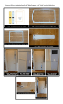
Step 5. Remove the Shipping Brackets
If your D20 I/O drawer was shipped preinstalled in a rack, you may want to remove the shipping brackets
from the rear rack EIA rails. The shipping brackets keep the rear of the I/O drawer from moving in a
side-to-side motion while being transported. They can, however, remain on the rack without interfering with
normal day-to-day operations. To remove them, do the following:
1. Go the the rear of the rack and open the rack’s rear door.
2. Remove the two screws that secure each shipping bracket to the rack’s EIA rails. See the following
illustration.
3. After removing the shipping brackets, reinstall the four retaining screws.
1 Rack EIA Rails
2 Shipping Bracket Retaining Screws and the Rear Rail to Rack Retaining
Screws
3 Shipping Brackets
Chapter 1. Setting Up the I/O Drawer 5

Step 6. Read the D20 I/O Drawer Cabling Precautions
Before installing the D20 I/O drawer into the rack and connecting the RIO-G and power control cables, do
the following:
1. Ensure that your system is running the latest level firmware. For information about checking or
upgrading the firmware level of your system, refer to the firmware updates section of your system’s
installation guide
2. After ensuring that your firmware is at the latest level, turn off the power and disconnect the system
unit’s power cables from the power source.
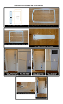
Step 7. Attach the Mounting Hardware to the Rack Enclosure
Before performing this procedure, read through each step and study the illustrations.
Attention: Mounting the rails is a complex procedure. To install the rack rails correctly, you must read,
and then perform each procedure step in the order given. Failure to do so may cause rail failure.
Note: If your rack has doors, remove the doors at this time. For information about removing the rack
doors, refer to your rack installation guide.
Locate the hardware-mounting kit, rack-mounting template, and the I/O drawer rails that were
shipped with your I/O drawer.
1 Rack-Mounting Template
2 Rack-Mounting Hardware Kit
3 I/O Drawer Rail Assemblies
6 D20 I/O Drawer Installation Guide
/