Page is loading ...

Features:
Overview:
Dimensions:
Parts List:
SD-H412
Electric Transfer Hinge
Manual
The ENFORCER SD-H412 Electric Transfer
Hinge provides a vandal-resistant method for
protecting and concealing wires between a
hollow door and door frame. It is suitable for
low-voltage, low-current applications such as
electric door strikes, locksets, and deadbolts
or other monitoring or exit devices and is
easily installed, replacing the center hinge.
1x Hinge 8x Wood Screws
8x Metal Screws 1x Manual
1x Mounting Template
Type
5-knuckle, 4-wire transfer hinge
with concealed wiring
Operating voltage 12~24 VAC/VDC
Current 28AWG 0.5@24VAC/VDC
Wires
4x 28AWG
(red, black, white, green)
Operating
temperature
-4°~185° F (-20°~85°C)
Dimensions 4
1
/
2
"x4
1
/
2
"x
1
/
8
"
Weight 16-oz (454g)
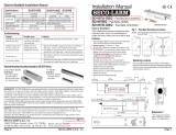
Fig. 1
Electric Transfe
r
Hinge installation
location
4
1
/
2
" (114 mm)
4
1
/
2
"
(114 mm)

ENFORCER Electric Transfer Hinge
2 SECO-LARM U.S.A., Inc.
Installation:
Important Notes:
PICGN3
MI_SD-H412_191001.doc
x
SECO-LARM
®
U.S.A., Inc.
16842 Millikan Avenue, Irvine, CA 92606 Website: www.seco-larm.com
Phone:
(
949
)
261-2999
|
(
800
)
662-0800 Email: sales
@
seco-larm.com
NOTICE: The SECO-LARM policy is one of continual development and improvement. For that reason, SECO-LARM
reserves the right to change specifications without notice. SECO-LARM is also not responsible for misprints.
A
ll trademarks
are the property of SECO-LARM U.S.A., Inc. or their respective owners. Copyright © 2019 SECO-LARM U.S.A., Inc. All
rights reserved.
WARRANTY:
This SECO-LARM product is warranted against defects in material and workmanship while used in normal
service for one
(
1
)
y
ear from the date of sale to the ori
g
inal customer.
1. The ENFORCER Electric Transfer Hinge is not meant to be load-bearing, and should
be installed in place of a center hinge.
2. Only one Electric Transfer Hinge can be installed in a single door.
3. Do not pick up the hinge by grabbing the wires and do not pull the wires as this may
damage them. Such resulting damage is not covered by the warranty.
4. Take care when feeding the wires through the door and frame wiring holes, make
sure not to crimp or damage the insulation.
5. Disassembling the hinge will void the warranty.
1. Using the included template, prepare the door frame and door for the hinge and drill
5
/
8
" (16mm) wiring holes in the door and frame to accommodate the wiring. Take care
to ensure that there are no burrs or sharp edges around the holes. Note: the Electric
Transfer Hinge is not designed to bear the load of the door, and thus should be
installed between the upper and lower load-bearing hinges (see Fig. 1).
2. Make the wiring connections.
3. After the wires are connected, gently feed the wires through the wiring holes in the
frame, taking care not to scratch the wire insulation or crimp any wires. Install the
hinge to the frame without tightening the mounting screws completely.
4. Repeat with the wires through the door’s wiring holes and install the hinge to the door.
Test by closing and opening the door, and if there are no problems, then tighten the
mounting screws on both the door and frame.
/