
Service Manual
0700 150 018 0002
LHQ 150
LTV 150
Caddy 150, Caddy Tig 150

Cod.92.08.020
Edition: 02/00
INDEX:
1) GUARANTEE CONDITIONS . . . . . . . . . . . . . . . . . . .2
2) PURPOSE OF THE MANUAL . . . . . . . . . . . . . . . . . .3
3) MACHINE TECHNICAL SPECIFICATIONS . . . . . . . .3
4) DESCRIPTION OF MACHINE PARTS . . . . . . . . . . . .4
5) DESCRIPTION OF MACHINE OPERATION . . . . . . .5
LAY-OUTS OF CARDS . . . . . . . . . . . . . . . . . . . . . . . .10
6) DESCRIPTION OF DIAGNOSTIC INDICATIONS :
- EXTERNAL . . . . . . . . . . . . . . . . . . . . . . . . . . . . . . .16
- INTERNAL . . . . . . . . . . . . . . . . . . . . . . . . . . . . . . . .17
7) SPARE PARTS LIST . . . . . . . . . . . . . . . . . . . . . . . . . .19
8) WARNINGS, PRECAUTIONS, GENERAL
INFORMATION ON EXECUTING REPAIRS . . . . . . . .20
9) DIAGNOSTIC AND REPAIR INSTRUMENTS
AND TOOLS . . . . . . . . . . . . . . . . . . . . . . . . . . . . . . .20
10) DIAGNOSIS PROCEDURE : . . . . . . . . . . . . . . . . . . .21
- LEVEL 1
- LEVEL 2
11) PARTS DISMANTLING AND RE-INSTALLATION
PROCEDURE . . . . . . . . . . . . . . . . . . . . . . . . . . . . .42
12) OPERATING TESTS AND SETTINGS . . . . . . . . . . . . .48
1) GUARANTEE CONDITIONS.
To specify the present warranty conditions , we remind that the
damages
a) resulting from attempts by personnel not allowed to install,
repair or service the products
b) resulting from improper use or connection to incompatible
equipment
c) in products that have been modified or integrated with other
products when such modification or integration can be the
cause of the failure are not repair under warrantly.
2 Guarantee conditions

Performance:
at 25% duty cycle
at 35% duty cycle
at 60% duty cycle
at 100% duty cycle
Setting range
Open circuit voltage
Mains supply:
voltage
frequency
fuse
mains cable , area
Enclosure class
Application class
Dimensions LxWxH
Weight
150 A/26 V
140 A/25,6 V
110 A/24,4 V
100 A/24 V
5-150 A
62 V
230 V AC
50/60 Hz
16 A*
3x1,5 mm2**
IP 23
375x145x280 mm
5,5 Kg
2) PURPOSE OF THE MANUAL
The purpose of this manual is to provide authorised technical
servicing centres the information required for repairing
LHQ150/LTV150.
To avoid serious damage to people and things, this manual must
be used strictly by qualified technicians.
What is involved in a repair job?: identifying the faulty part - as
this part is included in the list of available spare parts - and
replacing it according to the procedures described below.
If an electronic card is faulty, repair entails replacing the card
and not replacing the faulty electronic component on the card
itself.
If trouble cannot be solved by observing the procedures in the
manual, the machine must be sent back.
We suggest two diagnosis procedures on two levels: at the first
level, simple initial action instruments/tools are used, at the
second level, more sophisticated instruments/tools are used.
By taking into account the training level of its technicians and its
available instruments, each service centre can decide whether
to use the first or second procedure.
The order of the subjects in this manual is based on a logic that
gradually provides the repair technician with knowledge of the
machine. We therefore advise you to follow the suggested
order, by starting at the beginning.
Purpose of the manual - Machine technical specifications 3
3) MACHINE TECHNICAL SPECIFICATIONS .
Caddy 150 - LHQ 150
Caddy TIG 150 - LTV 150
Performance:
at 25% duty cycle
at 35% duty cycle
at 60% duty cycle
at 100% duty cycle
Setting range
Open circuit voltage
Mains supply:
voltage
frequency
fuse
mains cable , area
Enclosure class
Application class
Dimensions LxWxH
Weight
150 A/26 V
140 A/25,6 V
110 A/24,4 V
100 A/24 V
5-150 A
62 V
230 V AC
50/60 Hz
16 A*
3x1,5 mm2**
IP 23
375x145x280 mm
5,5 Kg

4 Description of machine parts
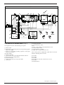
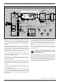
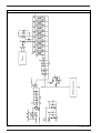
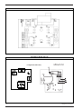
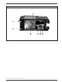
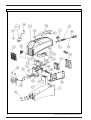
4) DESCRIPTION OF MACHINE PARTS. (see fig. 1)
The equipment consists of the following circuit parts:
a) Master switch
b) input filter for suppressing radio noise and protecting against
mains over-voltage.
c) resistors for pre-loading levelling capacitors and by-pass
relays for the resistors.
d) rectifier bridge
e) levelling capacitors
f) power inverter with over-temperature detection device.
g) clamp circuit (over-voltage limiter)
h) power transformer
i) rectifier circuit and current free-flow diode
j) load resistor
k) levelling inductance
l) current transducer (shunt)
m) fan
n) power circuits feeding control/adjustment circuits
o) current control circuits
p) control circuits (front panel)
q) output filter for suppressing radio noise
Some of these parts are independent, while others are housed
inside the following electronic cards:
A) Card AP1
B) Card AP2
C) Card AP3
D) Card AP4 (for LHQ 150) or AP4/01 (for LTV 150)
E) Card AP5
as illustrated below.
FIG. 1

Description of machine operation 5
5) DESCRIPTION OF MACHINE OPERATION.
Power is initially converted from AC to DC by the rectifier brid-
ge at input, and is then converted from DC to AC by an inver-
ter providing AC frequency of 100kHz. Power is then transfer-
red via an isolating transformer to the output circuits and is sub-
jected to a final AC to DC conversion by the output rectifier .
More details:
5.1)
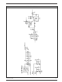
) Master switch (a) - input filter for suppressing radio noise
and protecting against power line over-voltage (b).
(see fig. 2)
The power cable takes the supply voltage and the ground pro-
tection to card AP1.
Only one phase of the supply voltage is switched by switch (a)
which is outside the card and connected to it by two appro-
priate bump contacts.
IMPORTANT !: When accessing parts inside the
machine, remember that turning off the switch will
not prevent the danger of electric shocks. We the-
refore advise you to remove the power plug and
wait for about a minute before attempting any job.
When the switch is turned on, input voltage is applied to the
power line over-voltage suppression circuit (b) - which consists
of a varistor (see note) - and is then filtered by the radio noise
suppression circuit (b) (see note).
The card also makes the grounding connection between the
yellow-green conductor coming from the power cable and the
cables coming from card AP3 .
NOTE : If the electrical component know as a varistor is placed
between the two power supply phases, when an instantaneous
voltage in excess of 275 V appears on its terminals, the varistor
very rapidly becomes conductive, absorbing a current peak
which is sufficient to limit the said over-voltage and it thus pro-
tects the other parts of the machine.
This process has no destructive effect on the component if the
energy generated by the voltage peak is low, as in the case of
atmospheric lightning strikes. If, however, over-voltage is high
and prolonged, the varistor cannot dissipate this high energy
and blows.
This happens if, for example, the machine is connected in error
to 400 Vac mains voltage, or following over-voltage caused by
non stabilised power units of inadequate capacity.
NOTE : The radio noise suppression circuit has two purposes:
to keep the machine's radio frequency emissions within limits
specified by standards and to ensure the equipment's immunity
against the same type of problems caused by any electronic
devices connected to the same power supply source.
The filter consists of a network of capacitors, some of which are
grounded, and a toroidal inductor.
FIG. 2

6 Description of machine operation
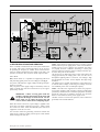
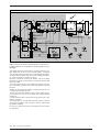
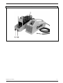
5.2)
resistors for pre-loading levelling capacitors and by-pass
relays for the resistors (c) - rectifier bridge (d) - levelling capacitors
(e) - power inverter with over-temperature detection device (f) -
clamp circuit (over-voltage limiter) (g) - power transformer (h).
(see fig. 3)
Power supply voltage reaches card AP2 via two small cables, and
at this point, is applied to the rectifier bridge (d) - levelling capa-
citors (e) by means of a soft start circuit (c) consisting of a pair of
power resistors in series with each other and installed in parallel
with respect to the contacts of a relay. (see note)
The by-pass relay is powered on 24 Vdc supplied by card AP1.
Rectified, filtered voltage is supplied to the power inverter section
(f), fitted on the card itself, and also to the control circuits power
supply section installed on card AP1.
The inverter has a forward structure with eight power mosfets in
parallel soldered directly on card AP2 and secured with screws to
the aluminium radiator.
Power up control for the mosfets is effected with PWM (Pulse
Width Modulation) technique at a frequency of about 100 kHz.
The control circuit is fitted on card AP2, receiving 18Vdc power
from AP1.
The radiator is cooled by a fan (m) powered by card AP1 at 15
Vdc. Air flows from the machine's rear grille (air intake) toward
the front grille (air outlet).
If, due to interruption of ventilating air or a heavy duty machi-
ne cycle, radiator temperature exceeds the permissible limit,
the thermal device on the radiator sends a signal to the control
logic which then shuts down the inverter and signals the fault to
the front panel.
The operating voltage of the inverter's power mosfets is limited
by a clamp circuit (g) consisting of an auxiliary mosfet of the
same type as the eight other mosfets above. This mosfet is secu-
red by a screw on the aluminium radiator, but is electrically iso-
lated from the radiator by insulating tape of low thermal resi-
stance.
The power transformer, constructed with planar technology and
also cooled by an adjacent radiator, is connected by two small
cables to card AP2.
IMPORTANT: When replacing card AP2, remember
that the order of securing the cables to the card is
extremely important.
NOTE : The purpose of the soft-start circuit is to limit absorp-
tion of current from the mains as soon as the machine is powe-
red up. In fact, in the absence of this circuit, at power up, the
filter capacitors would be charged instantly. Vice versa, a con-
trol circuit installed on card AP2, by commanding closure of the
by-pass relay with a few seconds delay, enables the capacitors
to be charged slowly through the two resistors.
FIG. 3

Description of machine operation 7
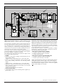
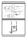
5.3)
rectifying circuit and free wheeling diode (I) - load resistor (j) -
levelling inductance (k) - output filter for suppressing radio noise (q).
(see fig. 4)
The output of the power transformer is connected to the two rec-
tifier diodes and to the two free wheeling diodes (I) soldered
onto card AP3 and secured by screws to the aluminium radiator.
The latter diodes together with the current levelling inductance
(k), ensure continuity of current at output.
Electrical connection between the diodes and the levelling
inductance is directly via the radiator, on which all cathodes and
diodes are fitted.
A 220 Ohm power resistor is also fitted to the radiator, and sup-
plies a minimum output load even when the machine is running
load free.
Similarly to the inverter, the radiator is located along the flow of
cooling air generated by the fan.
There is no temperature detection device on the radiator becau-
se protection is, in any event, assured by the inverter's thermal
protection.
A small capacitive filter connected to the ground circuit is also
fitted on card AP3 .
The output filter (q), housed inside card AP5, has the porpouse
to keep the machine’s radio frequency emission within limits
specified by standard.
It consists of a network of resistors and capacitors some of which
are grounded.
FIG. 4

8 Description of machine operation
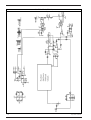
5.4)
Current transducer (shunt) (l) - power circuits for com-
mand/control circuits (n) - current control circuits (o).
(see fig. 5)
The equipment is essentially a direct current generator that can
be set by a potentiometer on the front panel. To effect this func-
tion, delivered current is measured by a current transducer (or
shunt), consisting of a constantan foil suitable gauged which is
connected at one end to the secondary winding of the power
transformer and, at the other, to the machine output.
The control circuit on card AP1 instantly compares the value of
requested and delivered current and sends the control signal to
the inverter modulator installed on card AP2.
This control circuit also measures the machine's output current
to provide the following functions:
- in MMA :
• increase of current when welding is started (hotstart); the fol-
lowing relation applies:
supplied current = requested current + 80% of the same
• increase of current if the electrode is short-circuited on the
piece during welding (anti-freeze); the following relation
applies :
supplied current = requested current + 30% of the same
• fold-back if, in spite of anti-freeze the short-circuit of the elec-
trode on the piece continues for a few tenths of a second; the
following relation applies:
supplied current limited to a few amperes
- in TIG (TOUCH START) :
• current limited at lift start; the following relation applies sup-
plied current = 10 A
Furthermore, due to safety standard problems, output voltage is
restricted to 62 Vdc, if measured according to the relevant stan-
dards, but is limited to 55-56 Vdc if measured with an ordinary
multimeter applied directly on the machine's output terminals.
By using switching point K1 of card AP1, the value of load free
output voltage can be lowered further to below 50 Vdc if called
for by special national or sector standards.
All the machine's electronic circuits are powered by voltages
produced by a switching power supply unit fitted on card AP1.
The following voltages are generated:
- with respect to GND reference potential
• +12Vdc for electronic circuits of card AP1
• -12Vdc for electronic circuits of card AP1
• +15Vdc to power the fan
- with respect to reference potential GND_PWR
• +18Vdc for electronic circuits of card AP2
• +24Vdc to power the relay of card AP2
GND is equipotential with respect to the shunt terminal, whereas
GND_PWR coincides with the output of the rectifier bridge (d).
The voltages listed above are generated in card AP1 commencing
with the rectified input voltage of 325Vdc (= 230V X V2) supplied
by the rectifier bridge (d) on card AP2.
FIG. 5

Description of machine operation 9
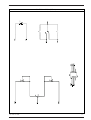
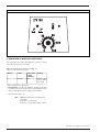
5.5)
Control circuits ( front panel ) (p).
(see fig. 6)
These circuits, which are contained in card AP4 fitted at the rear
of the machine front panel, enable the following:
- setting of welding current by means of the potentiometer
- selection of function mode MMA / TIG (LIFT)
When the selector switch is in MMA (right) position, load free
voltage is available on the machine terminals when it is powe-
red, and further, the hot-start, anti-freeze, and fold-back func-
tions are all enabled.
When the selector switch is in TIG (left) position, open circuit
voltage is on when the machine is powered and, furthermore,
current is limited to 10 A while the electrode is short-circuited
and until it is raised.
We shall talk about the LED on the panel later on.
Moreover, two potentiometers for setting delivered current are
fitted on card AP4, but can be accessed only when the machi-
ne is open. We shall discuss these later on.
NOTE: the difference between card AP4 and AP4/01 is explained
in section 12.
FIG. 6

10 Lay-outs of cards
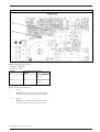
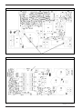
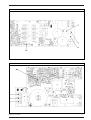
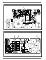
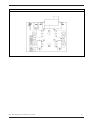
Card AP1 side A (FIG. 7A)

Lay-outs of cards 11
Card AP1 side B (FIG. 7B)

12 Lay-outs of cards
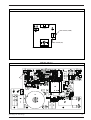
Card AP2 (FIG. 8)

Lay-outs of cards 13
Card AP2 side A (FIG. 8A)

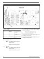
14 Lay-outs of cards
Card AP3 (FIG. 9A)
Card AP5 (FIG. 9B)

Lay-outs of cards 15
Card AP4 or AP4/01 (FIG. 10)

16 Description of diagnostic indications
6) DESCRIPTION OF DIAGNOSTIC INDICATIONS.
The equipment has LEDs with diagnostic functions on both
front panel and on electronic cards.
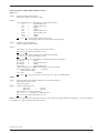
6.1)
External diagnostic indications.
(see fig. 11)
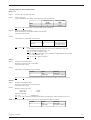
There is a LED on the front panel:
FIG. 11
Position
L1
Colour
YELLOW
Status under
normal
conditions
OFF
Meaning
Thermal pro-
tection device
NOT active
Further explanations of the above:
• YELLOW LED: This LED is off when the machine is operating
normally. It goes on to report inverter overtemperature, follo-
wed by interruption of power supply by the machine.
Therefore if the LED is on
then either the machine has exceeded work
cycle limits
or the fan is not operating
or air flow is obstructed from the outside

Description of diagnostic indications 17
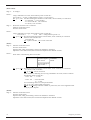
Card AP1 (FIG. 12)
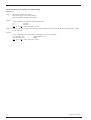
6.2)
Internal diagnostic indications.
- Card AP1 .
(see fig. 12)
There are two LEDs:
Position
L1
L2
Status under normal
conditions
ON
ON
Meaning
-12Vdc power ON
on Card
+12Vdc power ON
on Card
Further explanations of the above:
• L1 : If OFF
then there is a malfunction in the power circuit of
Card AP1 or there is a short circuit on Card AP2
L2 : If OFF
then there is a malfunction in the power circuit of
Card AP1 or there is a short circuit on Card AP2

18 Description of diagnostic indications
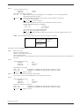
Card AP2 (FIG. 13)
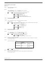
- Card AP2 .
(see fig. 13)
There are three LEDs:
Position
L1
L2
L3
Status under normal
conditions
ON
ON
See explanation
Meaning
+18dc power ON
on Card
+25Vdc power ON
on Card
Modulation level of
PWM
Further explanations of the above:
• L1 : If it is OFF
then there is either a malfunction in the power
circuit of Card AP1
or there is an electrical connection
problem on small cables n. 8 and n. 9.
or there is a short circuit on Card AP2
• L2 : If it is OFF
then there is either a malfunction in the power
circuit of Card AP1
or there is an electrical connection
problem on small cables n. 8 and n. 10.
or there is a short circuit on Card AP2
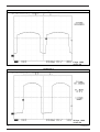
• L3 : The luminosity of this LED is not fixed but is in propor-
tion to the width of the inverter's PWM modulation.
Therefore, its luminosity is:
minimum when supplied power is low
maximum when supplied power is high
However, note the following special cases:
- machine running load free: medium luminosity (due to load
free voltage at machine output)
- in the absence of the control signal coming from the circuits
controlling the current of card AP1 (yellow-green shielded 2-
pole cable): maximum luminosity.

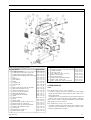
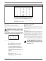
7) SPARE PARTS LIST
NOTE :
Item number 0700 150 011 (n.16) includes:
- Card AP2 complete with power mosfets and rectifier diode
bridge already soldered on the printed circuit in order to faci-
litate replacement.
- insulating tape to be inserted between the clamp mosfets and
radiator - this is useful if the tape on the radiator is damaged.
Power mosfets cannot be supplied separately, but the rectifier
diode bridge can. (0700 150 015)
Item number 0700 150 012 (n.17) includes:
- Card AP3 complete with power diodes pre-soldered on the
printed circuit, but without the load resistor, in order to faci-
litate the replacement procedure.
31
32
33
34
36
37
38
39
40
41
REAR GRID
MONOBLOC FRONT AND REAR SUPPORT
THERMIC WIRING
FUSE SMD 250V 1A
FLAT CABLE LINK SCH 243-2842
RIGHT PLASTIC PANEL
LEFT PLASTIC PANEL
COPPER BAR NEGATIVE/POSITIVE
MAINS CABLE (NEW TYPE)
INPUT AND LOGIC MMA PC-BOARD
0700 150 019
0700 150 020
0700 150 023
0700 150 024
0700 150 027
0700 150 028
0700 150 029
0700 150 030
0700 150 031
0700 150 032
Spare parts list 19
Pos.
1
2
3
4
5
6
7
8
9
10
11
12
13
14
15
16
17
18
19
20
21
22
23
24
25
27
28
30
Item number
0700 150 001
0700 150 002
0700 150 003
0700 150 004
0212 602 208
0193 307 104
0193 317 001
0321 475 881
0700 150 005
0366 306 881
0700 150 006
0700 150 007
0700 150 008
0700 150 009
0700 150 010
0700 150 011
0700 150 012
0456 574 001
0456 541 001
0468 208 001
0456 192 881
0700 150 013
0700 150 014
0700 150 015
0700 150 016
0700 150 021
0700 150 022
0700 150 025
Description
COVER (Lower part)
COVER WITH LHQ PLATE (Upper part)
COVER WITH LTV PLATE (Upeer part)
INVERTER TRANSFORMER WITH HEAT SINK
NUT
CABLE BUSH
MAIN SWITCH
KNOB
CONNECTOR
CONNECTOR
FAN
INPUT AND LOGIC MMA PC-BOARD
FRONT PC-BOARD, LHQ 150
FRONT PC-BOARD, LTV 150
OUTPUT FILTER PC-BOARD
POWER PC-BOARD KIT
SECONDARY RECTIFIER KIT
FILTER
FRONT GRATING
STRAP
MAINS CABLE
REPLACEMENT OF RELAY ON 15,18,012
REPLACEMENT OF VARISTOR
REPLACEMENT OF RECTIFIER DIODE
CLAMP FOR CARRYNG STRAP
CAPACITOR
RESISTOR 2x56 Ohm 5W
INNER FRONT GRID
TAB. 01
Caddy 150 (LHQ) and Caddy Tig 150 (LTV)

20 Warnings, precautions, general information - Diagnostics and repair instruments and tools
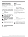
8) WARNINGS, PRECAUTIONS, GENERAL
INFORMATION ON EXECUTING REPAIRS.
Repairs may be executed by qualified personnel only.
Before attempting any repairs, we advise you to read and
understand the information in this manual, especially in regard
to safety recommendations.
Do not carry out any repair unless another person is present who
can provide help in case of an accident.
To repair equipment, access is necessary to the internal parts of
the machine, and to obtain this, some protective panels have to
be removed. Therefore, some extra precautions are necessary,
over and above those applying to normal use of the machine for
welding, in order to prevent any damaged caused by contact
with:
- Live parts
- moving parts
- parts at high temperature
- Live parts:
IMPORTANT !: When accessing parts inside the
machine, remember that turning off the switch will
not prevent the danger of electric shocks. We the-
refore advise you to remove the plug and wait for
about a minute before attempting any job.
Further, as capacitors charged with high voltage may be pre-
sent, wait about a minute before working on the internal parts.
IMPORTANT !: When taking measurements,
remember that the measuring instruments them-
selves can become live and, therefore, do not touch
their metal parts.
- Moving parts:
IMPORTANT !: Keep your hands well away from the
fan when the machine is connected to the power
supply. Make sure that the power plug is removed
and that the fan is idle before replacing it.
- Parts at high temperature:
IMPORTANT !: When you have to handle internal
parts of the machine, remember that some could
be at high temperature. In particular, do not touch
cooling radiators.
9) DIAGNOSTICS AND REPAIR INSTRUMENTS
AND TOOLS.
9.1)
Diagnostics instruments and tools
9.1.1)
Level 1
You will need the following:
- a multimeter with the following scales:
Ohm : from 0 to a few Mohm
Diode test
Direct voltages (Vdc): from mVdc to 500 Vdc
Alternate voltages (Vac): from 10 Vac to 500 Vac
NOTE : We recommend you to use an instrument with an auto-
matic scale, because, if the machine faulty, in theory, the level of
the electrical value to be measured cannot be foreseen.
- a shunt of 150 A @ 60 mV.
NOTE : Remember that other values may be equally suitable,
but you will sacrifice accuracy at larger capacities, whereas on
low capacities, rapid measuring is necessary to prevent the
shunt overheating.
9.1.2)
Level 2
In addition to the instruments and tools recommended at the
previous point, you will also need the following:
- an oscilloscope with the following characteristics :
- two channels
- 100MHz of passband
- time base up to 200ms, and ROLL option for the
trigger
- a probe with the following characteristics :
- attenuation of 100: 1
- insulating voltage to ground of at least 600Vrms.
IMPORTANT !: Any connection to the ground, whe-
ther direct or through the metal frame of the oscil-
loscope must be eliminated. However, we advise
you to make a ground connection for the oscillo-
scope through an in-series capacitor-resistor cir-
cuit, where C = 10 nF 1600 V, R = 220Kohm 1W.
Page is loading ...
Page is loading ...
Page is loading ...
Page is loading ...
Page is loading ...
Page is loading ...
Page is loading ...
Page is loading ...
Page is loading ...
Page is loading ...
Page is loading ...
Page is loading ...
Page is loading ...
Page is loading ...
Page is loading ...
Page is loading ...
Page is loading ...
Page is loading ...
Page is loading ...
Page is loading ...
Page is loading ...
Page is loading ...
Page is loading ...
Page is loading ...
Page is loading ...
Page is loading ...
Page is loading ...
Page is loading ...
Page is loading ...
Page is loading ...
-
 1
1
-
 2
2
-
 3
3
-
 4
4
-
 5
5
-
 6
6
-
 7
7
-
 8
8
-
 9
9
-
 10
10
-
 11
11
-
 12
12
-
 13
13
-
 14
14
-
 15
15
-
 16
16
-
 17
17
-
 18
18
-
 19
19
-
 20
20
-
 21
21
-
 22
22
-
 23
23
-
 24
24
-
 25
25
-
 26
26
-
 27
27
-
 28
28
-
 29
29
-
 30
30
-
 31
31
-
 32
32
-
 33
33
-
 34
34
-
 35
35
-
 36
36
-
 37
37
-
 38
38
-
 39
39
-
 40
40
-
 41
41
-
 42
42
-
 43
43
-
 44
44
-
 45
45
-
 46
46
-
 47
47
-
 48
48
-
 49
49
-
 50
50


Ask a question and I''ll find the answer in the document
Finding information in a document is now easier with AI
Related papers
-
ESAB LTV 150 User manual
-
-
-
-
-
-
-
-
-
Other documents
-
RTS Replacing the kp-12 power supply User manual
-
Abtus CAT-GA111R User Operating Manual
-
Beyerdynamic Unite Manager User manual
-
-
sako SUNSEE Owner's manual
-
Cebora 271 User manual
-
 Artcobell CAFE Series Installation guide
-
CEM STAR HV Rectifi er Retrofi t Operating instructions
-
-
Sharp PN-65TH1 Owner's manual
