Page is loading ...

UNITE AP4
ACCESS POINT
INSTALLATION INSTRUCTIONS
MONTAGEANLEITUNG


Table of Contents
1. Safety inructions. . . . . . . . . . . . . . . . . . . . . . . . . . . . . . . . . . . . . . . . . . . . . . . . . . . . . . . . . . . . . . . . . . . . . 6
2. Supplied accessories . . . . . . . . . . . . . . . . . . . . . . . . . . . . . . . . . . . . . . . . . . . . . . . . . . . . . . . . . . . . . . . . . . 8
3. Application . . . . . . . . . . . . . . . . . . . . . . . . . . . . . . . . . . . . . . . . . . . . . . . . . . . . . . . . . . . . . . . . . . . . . . . . . . . . 8
4. Connections and elements . . . . . . . . . . . . . . . . . . . . . . . . . . . . . . . . . . . . . . . . . . . . . . . . . . . . . . . . . . . . 9
5. Use10
6. Inallation. . . . . . . . . . . . . . . . . . . . . . . . . . . . . . . . . . . . . . . . . . . . . . . . . . . . . . . . . . . . . . . . . . . . . . . . . . . . 10
6.1 Mounting to a wall/ceiling . . . . . . . . . . . . . . . . . . . . . . . . . . . . . . . . . . . . . . . . . . . . . . . . . . . . . . . . 11
6.2 Mounting on a and. . . . . . . . . . . . . . . . . . . . . . . . . . . . . . . . . . . . . . . . . . . . . . . . . . . . . . . . . . . . . 13
6.3 Mounting on a VESA adapter plate. . . . . . . . . . . . . . . . . . . . . . . . . . . . . . . . . . . . . . . . . . . . . . . 15
6.4 Use a secondary safety rope. . . . . . . . . . . . . . . . . . . . . . . . . . . . . . . . . . . . . . . . . . . . . . . . . . . . . 17
7. How to use several Unite AP . . . . . . . . . . . . . . . . . . . . . . . . . . . . . . . . . . . . . . . . . . . . . . . . . . . . . . . . . . . 17
8. Technical specifications . . . . . . . . . . . . . . . . . . . . . . . . . . . . . . . . . . . . . . . . . . . . . . . . . . . . . . . . . . . . . . 18
Pin assignment. . . . . . . . . . . . . . . . . . . . . . . . . . . . . . . . . . . . . . . . . . . . . . . . . . . . . . . . . . . . . . . . . . . . . . . . . . . 20
Pinout RJ45. . . . . . . . . . . . . . . . . . . . . . . . . . . . . . . . . . . . . . . . . . . . . . . . . . . . . . . . . . . . . . . . . . . . . . . . . . . . . . . 20
Network build-up . . . . . . . . . . . . . . . . . . . . . . . . . . . . . . . . . . . . . . . . . . . . . . . . . . . . . . . . . . . . . . . . . . . . . . . . . 21
Dimensions. . . . . . . . . . . . . . . . . . . . . . . . . . . . . . . . . . . . . . . . . . . . . . . . . . . . . . . . . . . . . . . . . . . . . . . . . . . . . . . 38
Polar Pattern Antennas. . . . . . . . . . . . . . . . . . . . . . . . . . . . . . . . . . . . . . . . . . . . . . . . . . . . . . . . . . . . . . . . . . . 43
Inhaltsverzeichnis
1. Sicherheitsinformationen . . . . . . . . . . . . . . . . . . . . . . . . . . . . . . . . . . . . . . . . . . . . . . . . . . . . . . . . . . . . . 22
2. Lieferumfang . . . . . . . . . . . . . . . . . . . . . . . . . . . . . . . . . . . . . . . . . . . . . . . . . . . . . . . . . . . . . . . . . . . . . . . . . 24
3. Verwendung . . . . . . . . . . . . . . . . . . . . . . . . . . . . . . . . . . . . . . . . . . . . . . . . . . . . . . . . . . . . . . . . . . . . . . . . . . 24
4. Anschlüsse und Elemente. . . . . . . . . . . . . . . . . . . . . . . . . . . . . . . . . . . . . . . . . . . . . . . . . . . . . . . . . . . . . 25
5. Inbetriebnahme . . . . . . . . . . . . . . . . . . . . . . . . . . . . . . . . . . . . . . . . . . . . . . . . . . . . . . . . . . . . . . . . . . . . . . 26
6. Montage . . . . . . . . . . . . . . . . . . . . . . . . . . . . . . . . . . . . . . . . . . . . . . . . . . . . . . . . . . . . . . . . . . . . . . . . . . . . . 26
6.1 Montage an Wand/Decke . . . . . . . . . . . . . . . . . . . . . . . . . . . . . . . . . . . . . . . . . . . . . . . . . . . . . . . 27
6.2 Montage auf einem Stativ . . . . . . . . . . . . . . . . . . . . . . . . . . . . . . . . . . . . . . . . . . . . . . . . . . . . . . . 29
6.3 Montage auf VESA-Adapterplatte . . . . . . . . . . . . . . . . . . . . . . . . . . . . . . . . . . . . . . . . . . . . . . . 31
6.4 Sekundärsicherung (Sicherungsleine) verwenden. . . . . . . . . . . . . . . . . . . . . . . . . . . . . . . . 33
7. Mehrere Unite AP4 einsetzen. . . . . . . . . . . . . . . . . . . . . . . . . . . . . . . . . . . . . . . . . . . . . . . . . . . . . . . . . . 33
8. Technische Daten . . . . . . . . . . . . . . . . . . . . . . . . . . . . . . . . . . . . . . . . . . . . . . . . . . . . . . . . . . . . . . . . . . . . 34
Anschlussbelegung . . . . . . . . . . . . . . . . . . . . . . . . . . . . . . . . . . . . . . . . . . . . . . . . . . . . . . . . . . . . . . . . . . . . . . 36
Anschlussbelegung RJ45 . . . . . . . . . . . . . . . . . . . . . . . . . . . . . . . . . . . . . . . . . . . . . . . . . . . . . . . . . . . . . . . . . 36
Netzwerkaufbau. . . . . . . . . . . . . . . . . . . . . . . . . . . . . . . . . . . . . . . . . . . . . . . . . . . . . . . . . . . . . . . . . . . . . . . . . . 37
Abmessungen. . . . . . . . . . . . . . . . . . . . . . . . . . . . . . . . . . . . . . . . . . . . . . . . . . . . . . . . . . . . . . . . . . . . . . . . . . . . 38
Richtcharakteriik Antennen. . . . . . . . . . . . . . . . . . . . . . . . . . . . . . . . . . . . . . . . . . . . . . . . . . . . . . . . . . . . . 43

Unite AP4 – Access Point
4
This device complies with Pa 15 of the FCC Rules and with Indury Canada licence-exempt RSS
andard(s). Operation is subject to the following two conditions: (1) this device may not cause harmful
inteerence, and (2) this device mu accept any inteerence received, including inteerence that
may cause undesired operation.
Le présent appareil e conforme aux CNR d’Indurie Canada applicables aux appareils radio
exempts de licence. L’exploitation e autorisée aux deux conditions suivantes: (1) l’appareil ne doit pas
produire de brouillage, et (2) l’utilisateur de l’appareil doit accepter tout brouillage radioélectrique subi,
même si le brouillage e susceptible d’en compromettre le fonctionnement.
This equipment has been teed and found to comply with the limits for a Class A digital device,
pursuant to Pa 15 of the FCC Rules. These limits are designed to provide reasonable protection
again harmful inteerence when the equipment is operated in a commercial environment. This
equipment generates, uses, and can radiate radio frequency energy and, if not inalled and used in
accordance with the inruction manual, may cause harmful inteerence to radio communications.
Operation of this equipment in a residential area is likely to cause harmful inteerence in which case
the user will be required to correct the inteerence at his own expense.
Changes or modifications made to this equipment not expressly approved by Beyerdynamic may void
the FCC authorization to operate this equipment.
Radiofrequency radiation exposure Information:
For body worn operation, this equipment has been teed and meets the FCC RF exposure guidelines
when used with the Beyerdynamic accessories supplied or designated for this product. Use of other
accessories may not ensure compliance with FCC RF exposure guidelines.
Ee produto eá homologado pela Anatel, de acordo com os procedimentos regulamentados pela
Resolução n°. 242/2000 e atende aos requisites técnicos aplicados, incluindo os limites de exposição
da Taxa de Absorção Específica referente a campos elétricos, magnéticos e eletromagnéticos de
radiofrequência de acordo com as Resoluções n°. 303/2002 e 533/2009.
Japanese Radio Law and Japanese Telecommunications Business Law Compliance:
This device is granted pursuant to the Japanese Radio Law (電波法)
and the Japanese Telecommunications Business Law (電気通信事業法).
This device should not be modified (otherwise the granted designation number will become invalid).

Unite AP4 – Access Point
5
english
Country Approval
U
SA
C
anada
I
C: 3628C-UNITEAP4
E
urope
Japan
F
CC ID: OSDUNITEAP4
Compliance Information
T
he devices conforms to the EU guidelines
(EMC) 2014/30/EU
(LVD) 2014/35/EU
(RED) 2014/53/EU
as atteed by the CE mark.
R 202-SMH013
T D 19-0007 202

Unite AP4 – Access Point
6
The Unite AP4 access point has been designed for the wireless Unite communication system from
beyerdynamic. For detailed descriptions of its use, please refer to the operating instructions for the
complete system, which can be downloaded from the internet at www.beyerdynamic.com/unite .
1. Safety inructions
1. Read these inructions.
2. Keep these inructions.
3. Heed all warnings.
4. Follow all inructions.
5. Do not use this device near water.
6. Clean only with a dry cloth.
7. Do not inall near any heat sources such as radiators, heat regiers, oves, or other
apparatus (including amplifiers) that produce heat.
8. Do not modify the power plug of the supplied power cable.
9. Protect the power cable from being pinched or bent.
10. Only use accessories specified by the manufacturer.
11. Unplug this apparatus during lightning orms or when unused for long periods of
time.
12. Refer all servicing to qualified service personnel. Servicing is required when the
apparatus has been damaged in any way, such as power supply cord or plug is
damaged, liquid has been spilled or objects have fallen into the apparatus, the
apparatus has been exposed to rain or moiure, does not operate normally, or has
been dropped.
Disclaimer
• beyerdynamic GmbH & Co. KG will not be liable if any damage, injury or accident occurs
due to negligent, incorrect or inappropriate operation of the product.
Location
• If you transpo the equipment to another location take care to ensure that it is
adequately secured and can never be damaged by being dropped or by impacts on
the equipment.
Fire hazard
• Never place naked flames (e.g. candles) near the equipment.
Humidity / heat sources
• Never expose the equipment to rain or a high level of humidity. For this reason do not
inall it in the immediate vicinity of swimming pools, showers, damp basement rooms
or other areas with unusually high atmospheric humidity.
• Never place objects containing liquid (e.g. vases or drinking glasses) on the equipment.
Liquids in the equipment could cause a sho circuit.
• Do not inall near any heat sources such as radiators, heat regiers, oves or other
apparatus (including amplifiers) that produce heat.
Connection
• Protect all cables from being walked on or pinched.
• Lay all connection cables so that they do not present a trip hazard.
• Whenever working on the inputs and outputs of the equipment switch o power.

Unite AP4 – Access Point
7
english
• Check whether the connection figures comply with the exiing mains supply. Serious
damage could occur due to connecting the syem to the wrong power supply. An
incorrect mains voltage could damage the equipment or cause an electric shock.
• Please note that dierent operating voltages require the use of dierent types of power
cable and plugs.
Please refer to the following table:
• If the equipment causes a blown fuse or a sho circuit, disconnect it from the mains
and have it checked and repaired.
• Do not hold the power supply with wet hands. There mu be no water or du on the
contact pins. In both cases you could receive an electric shock.
• The mains cable mu be firmly connected. If it is loose there is a fire hazard.
• Always pull out the power supply from the mains and/or from the equipment by the
plug – never by the cable. The cable could be damaged and cause an electric shock or
fire.
• Do not use the equipment if the power supply is damaged.
• If you connect defective or unsuitable accessories, the equipment could be damaged.
Only use connection cables available from or recommended by beyerdynamic. If you
use cables you have made up yourself, all claim to warranty is null and void.
• In order to switch o the device disconnect the power plug from the power socket.
Disconnect
• For pluggable equipment, the socket-outlet shall be near the equipment and shall be
easily accessible.
Wall/ceiling mounting
• Before mounting the Unite AP4 to the wall/ceiling, make sure that there are no electrical,
or gas lines or water pipes behind the planned drilling locations. If necessary, check this
with a line detector or ask an expe.
It is a significant hazard when electrical or gas lines or water pipes are damaged
during drilling.
Maintenance
• Only clean the device with a slightly damp or dry cloth. Never use solvents as these
damage the suace.
Trouble shooting / servicing
• Do not open the device without authorisation.
• Leave all service work to authorised expe personnel.
Switching o
• The device does not have a separate on-o switch. To turn power o, unplug the power
cable from the AC/DC outlet. Make sure that you do not pull on the cable, but on the
mains plug.
Voltage Power plug according to standard
110 to 125 V UL817 and CSA C 22.2 no 42.
220 to 230 V CEE 7 page VII, SR section 107-2-D1/IEC 83 page C4.
240 V BS 1363 (1984): “Specification for 13A fused plugs and switched and un-switched socket outlets.”

Unite AP4 – Access Point
8
Disposal
This symbol on the product, in the instructions or on the packaging means that
your electrical and electronic equipment should be disposed at the end of its
life separately from your household waste. There are separate collection
systems for recycling in the EU. For more information, please contact the local
authority or your retailer where you purchased the product.
Simplified EU declaration of conformity
beyerdynamic hereby declares that the wireless transmission device complies with the EU
Directive 2014/53/EU (RED). The complete text of the EU declaration of conformity is
available online at the following address: http://www.beyerdynamic.com/cod
Trademark
The Dante® word mark and logos are regiered trademarks of Audinate Pty. Ltd and all
use of these trademarks by beyerdynamic is licensed. Other trademarks and trade names
are the propey of the respective owners.
3. Application
The Unite AP4 access point is a multifunctional device with which you can implement
dierent applications. The device is integrated into an exiing network via an Ethernet
cable. Depending on the configuration via the separate Unite Manager Soware
(operating inructions at www.beyerdynamic.com), the device works as a transmitter,
receiver or transceiver.
For each device there are a maximum of 4 DECT channels available. As 8 Unite AP4
devices can be connected to each other, a maximum of 32 DECT-channels can be
implemented.
2. Supplied accessories
1 x Unite AP4
1 x Inallation inructions
1 x Power supply with power cable,
depending on the country variant
1 x Thread adapter 1/2" – 3/8"
2 x Phoenix® plug-in terminal block, 2-row,
6-pin, contact spacing 3.5 mm
4 x Cover plates for mounting panel
4 x M5x10 screws (for Vesa adapter plate)
4 x M5 nut (for Vesa adapter plate)
Ventilation
• Do not inse objects into the ventilation and other openings. You could damage the
device and/or injure yourself.
Measures to prevent damage
• Do not disassemble or make any changes to the device.
• Do not transpo the device while it is mounted on a tripod as this may result in injury or
accidents. Make sure that the tripod is solid enough to hold the device.
• Do not drop the unit and do not expose it to rong physical ress such as shock or
vibration.

Unite AP4 – Access Point
9
english
Status LED
DC connection for the external, supplied power supply, 12 V DC / 3 A
Impoant: Use only the power supply supplied by beyerdynamic.
Dante® network connection with Power over Ethernet (PoE) function, RJ-45-socket
Reset button to reore the factory settings
LAN connection for configuration via the Unite Manager Soware, RJ-45-socket
USB connection
Sync signal input to cascade several Unite AP4, RJ-45-socket
Attention: No Ethernet connection!
Sync signal output to cascade several Unite AP4, RJ-45-socket
Attention: No Ethernet connection!
Audio inputs/outputs, channel 1 - 4, Phoenix®-terminal block socket for use with
supplied Phoenix terminal blocks, contact spacing 3.5 mm
4. Connections and elements
Front view
Rear view

Unite AP4 – Access Point
10
5. Use
You will find a detailed description of the use/configuration of the Unite AP4 in the
separate manuals “Unite Syem Manual” and “Unite Manager Soware”.
6. Inallation
In order to ensure that the Unite receivers receive radio signals as good as possible, make
sure that the front of the Unite AP4 unit points to the area where the Unite receivers will be
operating. If reception problems occur, change the mounting position of the Unite AP4 in
the room. Make sure that there is a line of sight between the Unite AP4 and the receivers.
This can improve reception.
In order to inall the Unite AP4 and to connect the cable, you mu remove the mounting
plate from the housing fir. Please proceed as follows:
• Press the latches on the right and le hand side inwards.
• Remove the mounting panel downwards, refer also to the arrow in the drawing.

Unite AP4 – Access Point
11
english
6.1 Mounting to a wall/ceiling
Caution:
• Before mounting the Unite AP4 to the wall/ceiling, make sure that there are no electrical,
or gas lines or water pipes behind the planned drilling locations. If necessary, check this
with a line detector or ask an expe.
• It is a significant hazard when electrical or gas lines or water pipes are damaged
during drilling.
Attention:
• For wall mounting, use appropriate wall plugs and screws.
Example: For a wooden wall use a universal screw, 4.5 x 30mm, pan head,
e.g. WIROX®-0201010450303
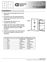
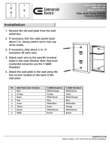
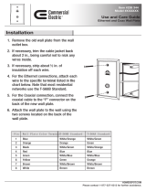
1. Remove the cover plates from the
mounting panel by pressing the large
latch.
2. Route all required connecting cables
through the openings of the mounting
panel.

Unite AP4 – Access Point
12
5. Connect the cables to the appropriate
connections.
Attach the cable with a cable tie to the
T-piece below the connection.
6. Put the device onto the mounting
panel until the latches on the right and
le hand side audibly click into place.
Refer also to the inallation
inructions on the mounting panel.
Attention: Please make sure that the
device is firmly mounted.
3. Mount the cover plates to the
mounting panel according to the
cable routing.
4. Mount the mounting panel to the wall
or ceiling by using the three “keyhole
openings” with appropriate screws.
C
able routing
d
ownwards
C
able routing
b
ackwards

Unite AP4 – Access Point
13
english
6.2 Mounting on a and
1. Press the cover plates on the large
latch from the mounting panel.
2. Route all required connecting cables
through the openings of the mounting
panel.
3. Attach the cover plates to the
mounting panel according to the
downward cable routing.
4. Connect the cables to the appropriate
connections.
Cable routing
downwards
Cable routing
backwards

Unite AP4 – Access Point
14
5. Attach the cable with a cable tie to the
T-piece below the connection.
6. Replace the mounting panel until the
latches on the right and le hand side
audibly click into place.
7. Mount the Unite AP4 on the thread of a
tripod with 5/8 thread.
For tripods with a 1/2" or 3/8 thread,
delivery includes an appropriate
adapter.
Upon reque, you can screw this
adapter into the 5/8 thread with a
flat-head screwdriver..

Unite AP4 – Access Point
15
english
6.3 Mounting on a VESA adapter plate
1. Attach a VESA 75 x 75 plate with
4 screws (included in the delivery) via
the 4 holes to the mounting panel. The
diances between the 4 holes are
75 mm each.
Attention: When selecting the screws,
make sure that the screw is flush with
the nut and does not protrude into the
device.
2. Faen the 4 screws on the inside of the
mounting panel with hex nuts.
Size of the nut: M5
3. Remove the cover plates from the
mounting panel by pressing the large
latch.
4. Route all required connecting cables
through the openings of the mounting
panel.
X4 X4

Unite AP4 – Access Point
16
5. Mount the cover plates to the
mounting panel according to the
cable routing downwards.
6. Connect the cables to the appropriate
connections.
Attach the cable with a cable tie to the
T-piece below the connection.
7. Replace the mounting panel until the
latches on the right and le hand side
audibly click into place.
Attach the Unite AP4 to the desired
place via the VESA plate.
Attention: Make sure that the device is
firmly mounted.

Unite AP4 – Access Point
17
english
6.4 Use a secondary safety rope
The Unite AP4 has two openings through which you can route a secondary safety rope to
secure the Unite AP4 additionally again falling down.
In practice, it is the quality of the way in which the equipment is installed that influences
the safety of suspension systems for lighting, PAs, monitors, decorations and other objects
in the production and event business which are installed using fixing devices intended to
allow the equipment to be used in dierent places (e.g. spigots and sleeves or C hooks).
Such applications thus require a secondary safety component.
(Source: DGUV Safety for Events and Productions Version 3.2/2015-10)
For the preferred direction of threading, refer to the arrow in the drawing.
7. How to use several Unite AP
A maximum of 8 Unite AP4 can be connected with each other so that 32 channels can be
sent, received or sent and received – depending on the configuration.
• To synchronise the devices, connect the sync signal output of the fir Unite AP4 to the
sync signal input of the second Unite AP4.
Use Cat 5e AWG 24/1 F/UTP cables or better.
The assignment mu be 1:1.
• Connect the Sync signal output of the second Unite AP4 to the Sync signal input of
the third Unite AP4 etc.
• The fir device acts as Sync Maer so that each subsequent device receives a clock
signal from the Sync Maer. In this way the individual DECT channels of the devices are
clocked. When using more than one Unite AP4 the synchronisation is absolutely
necessary to ensure the operation.
...8
Sync Maer
Synced Synced
Synced
min. 2m
1278
min. 2m
OUT
IN
OUT
IN
OUT
IN

Unite AP4 – Access Point
18
8. Technical specifications
External power supply
Input voltage . . . . . . . . . . . . . . . . . . . . . . 100 – 240 V AC, 47-63 Hz
Input current . . . . . . . . . . . . . . . . . . . . . . max. 0,8 A
Output voltage . . . . . . . . . . . . . . . . . . . . 12 V DC
Output current. . . . . . . . . . . . . . . . . . . . . 3 A
Power cable . . . . . . . . . . . . . . . . . . . . . . . included, depending on the region
Cable length . . . . . . . . . . . . . . . . . . . . . . 2 m [2.19 yds.]
Unite AP4
DECT RF frequency range . . . . . . . . . . . . . 1880 - 1930 MHz, depending on the country
DECT transmission power . . . . . . . . . . . . . . up to 250 mW (peak), depending on the country
DECT operating range . . . . . . . . . . . . . . . . . up to 300 m outside (line of sight);
the actual operating range depends upon the
RF output settings, the surroundings, the signal
absorption, signal reflection and signal interference
RF coverage . . . . . . . . . . . . . . . . . . . . . . . . . . . up to 10,000 m
2
; the actual coverage depends upon the
RF output settings, the surroundings, the signal absorption,
signal reflection and signal interference
Audio bandwidth
High quality (HD) . . . . . . . . . . . . . . . . . . . . . 50 Hz - 14 kHz (-3 dB)
Operating mode. . . . . . . . . . . . . . . . . . . . . . . Broadcast (4 channels)
Encryption . . . . . . . . . . . . . . . . . . . . . . . . . . . . . AES-256 bit encryption
Antenna . . . . . . . . . . . . . . . . . . . . . . . . . . . . . . . Diversity, internal
Polar pattern of antennas . . . . . . . . . . . . . two omnidirectional antennas with front-facing main lobe
Minimum distance between
several Unite AP4 devices . . . . . . . . 2 m [2.19 yds.]
Connections. . . . . . . . . . . . . . . . . . . . . . . • Ethernet (RJ 45)
• USB-C (currently not implemented)
• DC input, DC 12 V, power consumption max. 12 W
• Sync input (RJ 45)
• Sync output (RJ 45)
• Digital: Dante® (RJ 45; PoE: 12 W IEEE 802.3af-2003,
36 V - 57 V, only 48 kHz sample rate supported)
• Analogue: Phoenix® socket, balanced,
contact spacing 3.5 mm [0.14"], two-rowed, 6-pin,
balanced and shielded connecting cables required
Input level (4-channel In): max. +7 dBu
Input level for 0 dBFS @ 0 dB Gain: +5 dBu
Attention:
• If several Unite AP4 are used in one room, a minimum diance of 2 m mu be
maintained between the individual units to avoid radio diurbances.
The cable length
between two devices must not exceed 100 m. The total length of all Sync cables used to
connect the Unite AP4 devices to each other must not exceed 700 m.

Unite AP4 – Access Point
19
english
Required cable features for RJ 45 Ethernet, Dante® and Sync connectors
Cable type. . . . . . . . . . . . . . . . . . . . . . . Cat 5e AWG 24/1 F/UTP, shielded, assignment 1:1
Cable length for Ethernet,
Dante® and Sync. . . . . . . . . . . . . . . . . 100 m [109 yds.]
Total length of all Sync cables . . . max. 700 m [766 yds.]
Reset button. . . . . . . . . . . . . . . . . . . . . . . to restore the factory settings (network, audio, DECT)
Network default . . . . . . . . . . . . . . . . . . . DHCP (IP)
Indicator . . . . . . . . . . . . . . . . . . . . . . . . . . Status LED
Mounting for Vesa mount . . . . . . . . . . 75 x 75 mm [2.95" x 2.95"]
Mounting holes for
secondary safety rope. . . . . . . . . . . available (safety rope not included in the delivery)
Temperature range
Operation. . . . . . . . . . . . . . . . . . . . . . . . . . . . 0 to +40 °C [32 to 104 °F]
Storage . . . . . . . . . . . . . . . . . . . . . . . . . . . . . . -20 to +50 °C [-4 to 122 °F]
Relative humidity . . . . . . . . . . . . . . . . . . . . . . 0 to 90%
Dimensions (L x W x H). . . . . . . . . . . . . . 260 x 252 x 48 mm [10.2" x 9.92" x 1.89"]
Weight. . . . . . . . . . . . . . . . . . . . . . . . . . . . . 860 g [30.34 oz.]

Unite AP4 – Access Point
20
Pinout RJ45
1 white/green 5 white/blue
2 green 6 orange
3 white/orange 7 white/brown
4 blue 8 brown
Important:
Please use shielded connector housings. Twist the shield of the cable and fold it back-
wards so that a connection between the shield of the cable and the connector housing is
created when crimping the strain relief of the cable.
Use either the T-568A or T-568B pin assignment for both cable ends. Do not use both pin
assignments for one cable.
1 2 3 4 5 6 7 8
shielded connector
housing
T-568A
1 white/orange 5 white/blue
2 orange 6 green
3 white/green 7 white/brown
4 blue 8 brown
1 2 3 4 5 6 7 8
shielded connector
housing
T-568B
SF/UTPSF/UTP
ControlReset
Green = Activity
Y
ellow = Link
Green = Activity
Y
ellow = Link
/ PoE
USB
DC In
12 V 3 A
Sync In Sync Out
Not for Ethernet!
Analog Out + 4 dBu
Analog In + 6 dBu
12 34
1
2
3
4
+
-
+
-
+
-
+
-
+
-
+
-
+
-
+
-
Pin assignment
/