PLUS Vision Projector V-807 User manual
- Category
- Data projectors
- Type
- User manual
This manual is also suitable for

PO
W
E
R
AUTO
MENU
S
TAT
US
POWER
SOURCE
QUICK
MENU
O
N
O
F
F
F
R
E
E
Z
E
M
U
T
E
P
IP
D
IG
IT
A
L
R
G
B
Y
P
b
P
r
V
ID
E
O
S
-V
ID
E
O
Y
C
b
C
r
Q
U
IC
K
ENTER
Z
O
O
M
VOL
VKSTN
HKSTN
CANCEL
M
E
N
U
A
S
P
E
C
T
A
U
T
O
P
O
W
E
R
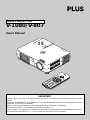
DATA PROJECTOR
V-1080/V-807
User’s Manual
IMPORTANT
Digital Light Processing, DLP, Digital Micromirror Device and DMD are all trademarks of Texas Instru-
ments.
Windows 98, Windows 95, and Windows 3.1 are registered trademarks in the United States and other
countries of Microsoft Corporation.
IBM is a registered trademark of International Business Machines Corporation.
Macintosh and MAC are trademarks of Apple Computer Inc.
Other names of companies and products mentioned are trademarks and registered trade-marks of
the respective companies. TM , ® and © marks are not used in this document.

E-2
IMPORTANT SAFETY INFORMATION
Precautions
Please read this manual carefully before using your PLUS V-1080 / V-807 Data Projector and
keep the manual handy for future reference.
CAUTION
TO PREVENT SHOCK, DO NOT OPEN THE CABINET. NO USER-SERVICEABLE
PARTS INSIDE. REFER SERVICING TO QUALIFIED PLUS SERVICE PERSONNEL.
This symbol warns the user that uninsulated voltage within the unit may have
sufficient magnitude to cause electric shock. Therefore, it is dangerous to
make any kind of contact with any part inside of this unit.
This symbol alerts the user that important literature concerning the opera-
tion and maintenance of this unit has been included. Therefore, it should be
read carefully in order to avoid any problems.
The above cautions are given on the bottom of the product.
WARNING
TO PREVENT FIRE OR SHOCK, DO NOT EXPOSE THIS UNIT TO RAIN OR MOIS-
TURE. DO NOT USE THIS UNIT’S GROUNDED PLUG WITH AN EXTENSION CORD
OR IN AN OUTLET UNLESS ALL THREE PRONGS CAN BE FULLY INSERTED. DO
NOT OPEN THE CABINET. THERE ARE HIGH-VOLTAGE COMPONENTS INSIDE. ALL
SERVICING MUST BE DONE BY QUALIFIED PLUS SERVICE PERSONNEL.
WARNING
This is a class A product. In a domestic environment this product may cause radio inter-
ference in which case the user may be required to take adequate measures.
RF Interference
WARNING
The Federal Communications Commission does not allow any modifications or changes
to the unit EXCEPT those specified by PLUS Technologies in this manual. Failure to
comply with this government regulation could void your right to operate this equipment.
This equipment has been tested and found to comply with the limits for a Class A digital
device, pursuant to Part 15 of the FCC Rules. These limits are designed to provide rea-
sonable protection against harmful interference when the equipment is operated in a
commercial environment. This equipment generates, uses, and can radiate radio fre-
quency energy and, if not installed and used in accordance with the instruction manual,
may cause harmful interference to radio communications. Operation of this equipment in
a residential area is likely to cause harmful interference in which case the user will be
required to correct the interference at his own expense.

E-3
Important Safeguards
These safety instructions are to ensure the long life of the unit and to prevent fire and shock.
Please read them carefully and heed all warnings.
Installation
•For best results, use the unit in a darkened room.
• Place the unit on a flat, level surface in a dry area away from dust and moisture.
• Do not place the unit in direct sunlight, near heaters or heat radiating appliances.
• Exposure to direct sunlight, smoke or steam can harm internal components.
• Handle the unit carefully. Dropping or jarring can damage internal components.
• Do not place heavy objects on top of the unit.
Power Supply
• The unit is designed to operate on a power supply of 100 - 240 V 50/60 Hz AC. Ensure
that your power supply fits these requirements before attempting to use the unit.
•For PLUGGABLE EQUIPMENT, the socket-outlet shall be installed near the equipment
and shall be accessible.
• Handle the power cable carefully and avoid excessive bending. A damaged cord can
cause electric shock or fire.
• Disconnect the power cable (mains lead) from the power outlet after using the unit.
Before disconnecting the power cable, make sure that the POWER indicator lights in
amber (not blinking or in green).
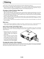
Cleaning
• Disconnect the power cable (mains lead) from the unit.
• Clean the cabinet of the unit periodically with a damp cloth. If heavily soiled, use a mild
detergent. Never use strong detergents or solvents such as alcohol or thinner.
• Use a blower or lens paper to clean the lens, and be careful not to scratch or mar the
lens.
• Clean the ventilation slots and speaker grills on the unit periodically using a vacuum
cleaner. If accumulated dust blocks the ventilation slots, the unit will overheat, which may
cause the unit to malfunction.
Use a soft brush attachment when using the vacuum cleaner. Do not use a hard attach-
ment, such as a crevice tool, to prevent the damage to the unit.
Lamp Replacement
• Be sure to replace the lamp when the Status indicator comes on. If you continue to use
the lamp after 1000 hours of usage, the lamp will turn off.
IMPORTANT SAFETY INFORMATION

E-4
Fire and Shock Precautions
• Ensure that there is sufficient ventilation and that vents are unobstructed to prevent the
buildup of heat inside the unit. Allow at least 10 cm (3 inches) of space between the unit
and walls.
• Prevent foreign objects such as paper clips and bits of paper from falling into the unit. Do
not attempt to retrieve any objects that fell into the unit. Do not insert any metal objects
such as a wire or screwdriver into the unit. If something should fall into the unit, immedi-
ately disconnect the power cable from the unit and have the object removed by a quali-
fied PLUS service person.
• Do not place any liquids on top of the unit.
• Do not look into the lens while the unit is on. Serious damage to your eyes could
result.
Carrying around
When carrying the unit around, please use the carrying case that comes with it and, to protect
the lens from scratches, always shut the sliding lens cap. Also, do not subject the unit to
strong mechanical shock.
IMPORTANT SAFETY INFORMATION

E-5
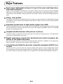
Major Features
Book-sized, lightweight (at about 0.9 kg/2.0 lbs) and small high-inten-
sity mobile projector
DMD
TM
and the synergistic effects of our own optical design serve to improve the optical utilization
efficiency. The three light sources (RGB) required in color expression are reproduced with one DMD
TM
.
These factors have enabled a design that offers both high intensity and small size/lightweight fea-
tures.
Sharp, clear picture
The absence of RGB color infidelity and the inconspicuous gaps between the individual dots permit
the display of small characters and diagrams with distinct clarity. An up-close look reveals the differ-
ence even more.
Beautiful reproduction of high-quality images from DVD
Faithful reproduction of color tones gives rise to the display of natural images. High-quality images
such as those from DVD and other sources bring out the display capabilities that are an essential
strength of the digital projector.
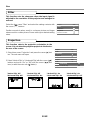
Heightened effectiveness with picture in picture
The video image is projected as a sub-picture within the personal computer picture. This expands the
usefulness of the projector even more.
Digital technology corrects the horizontal and vertical keystone dis-
tortion of the projected picture
New technology is used to correct the horizontal keystone distortion in addition to the regular key-
stone correction. This permits even simpler setup adjustments.
Connection permitted for personal computers equipped with DVI con-
nectors
Inclusion of a DVI connector allows the input of analog RGB signals as well as digital RGB signals.
(The supplied conversion cable supports personal computers having a regular analog RGB connec-
tor. See the Table of Supported Frequencies on Page 69 for information about display resolution.)

E-6
Table of Contents
Preparation and Background Knowledge
IMPORTANT SAFETY INFORMATION ............................................................................ E-2
Major Features ................................................................................................................. E-5
Table of Contents............................................................................................................. E-6
Checking the Supplied Accessories.............................................................................. E-8
Names of the Main Unit Parts ....................................................................................... E-10
Names of the Remote Control Parts ............................................................................ E-12
Preparing the Remote Control...................................................................................... E-13
Button Battery Replacement ..................................................................................... E-13
Remote Control Range ............................................................................................. E-14
Setup and Projection
The Procedure Up to Projecting to the Screen ........................................................... E-15
Placement Guide
V-807 Screen Size and Projection Distance.............................................................. E-16
V-1080 Screen Size and Projection Distance............................................................ E-17
Connecting Personal Computers and Video Equipment
Connections with PC Connectors
Personal Computers with a DVI Connector......................................................... E-18
Personal Computers with a Mini D-Sub 15-Pin Connector ................................. E-19
To Output the External Output Signal of a Notebook Computer ......................... E-20
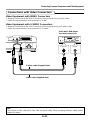
Connections with Video Connectors
Video Equipment with VIDEO Connectors.......................................................... E-21
Video Equipment with S-VIDEO Connectors ...................................................... E-21
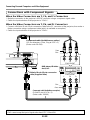
Connections with Component Signals
When the Video Connectors are Y, Cb, and Cr Connectors................................ E-22
When the Video Connectors are Y, Pb, and Pr Connectors ................................ E-22
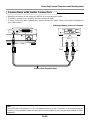
Connections with Audio Connectors ......................................................................... E-23
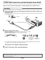
Power Cable Connections and Switching the Power On/Off
Operating................................................................................................................... E-24
Finishing .................................................................................................................... E-25
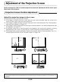
Adjustment of the Projection Screen
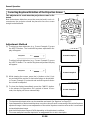
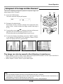
Projection Screen Position Adjustment ..................................................................... E-26
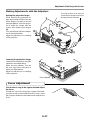
Making Adjustments with the Adjusters .............................................................. E-27
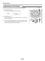
Focus Adjustment...................................................................................................... E-27
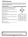
General Operation
Input Selection ............................................................................................................... E-28
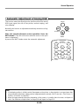
Automatic Adjustment of Analog RGB ........................................................................ E-29
Selection of Aspect Ratio ............................................................................................. E-30
Projecting a Sub-Picture ............................................................................................... E-31
Freezing a Moving Picture ............................................................................................ E-31
Cancelling Video and Audio Temporarily..................................................................... E-31
Using the Quick Menu ................................................................................................... E-32
Correcting Keystone Distortion of the Projection Screen ......................................... E-34
Enlargement of the Image and Video Movement ........................................................ E-35
Adjustment of the Volume............................................................................................. E-36

E-7
Menu Operations
Menu Operation Method................................................................................................ E-37
Names and Functions of the Parts ............................................................................ E-37
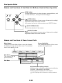
Names and Functions of the Remote Control Buttons that Operate Via a Menu ...... E-37
Names and Functions of the Main Unit Buttons Used in Menu Operation ................ E-38
Names and Functions of Menu Screen Parts............................................................ E-38
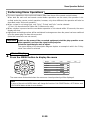
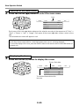
Performing Menu Operations .................................................................................... E-39
Selecting Another Menu Name with Remote Control Operation ............................... E-43
List of Item Names Offering Input Selection and Adjustments/Settings .................... E-44
Adjustments and Settings
Picture
Brightness / Contrast / Color / Tint / Sharpness ........................................................ E-46
Picture Adjustment / Fine Picture / H Position / V Position........................................ E-47
Reset ......................................................................................................................... E-48
Color
Gamma ..................................................................................................................... E-49
Color Temp. ............................................................................................................... E-49
Color System............................................................................................................. E-50
Color Space .............................................................................................................. E-50
View
Aspect ....................................................................................................................... E-51
Filter .......................................................................................................................... E-52
Projection .................................................................................................................. E-52
Keystone.................................................................................................................... E-53
Picture in Picture ....................................................................................................... E-54
Setup
Language .................................................................................................................. E-55
Auto Source............................................................................................................... E-55
Auto Power Off .......................................................................................................... E-56
On Screen ................................................................................................................. E-56
Menu Position ............................................................................................................ E-57
YPbPr ........................................................................................................................ E-57
Background ............................................................................................................... E-57
White Balance ........................................................................................................... E-58
Info.
Status ........................................................................................................................ E-59
Factory Default .......................................................................................................... E-59
Lamp Timer Reset..................................................................................................... E-59
Resolution / Frequency ............................................................................................. E-60
Lamp Timer ............................................................................................................... E-60
Miscellaneous
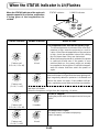
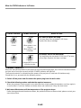
When the STATUS Indicator is Lit/Flashes.................................................................. E-61
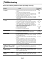
Troubleshooting............................................................................................................. E-63
Cleaning ......................................................................................................................... E-65
Replacing the Lamp Cartridge ..................................................................................... E-66
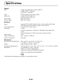
Specifications ................................................................................................................ E-69
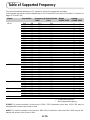
Table of Supported Frequencies .................................................................................. E-70
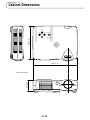
Cabinet Dimensions ...................................................................................................... E-71
Table of Contents

E-8
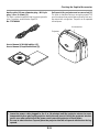
Checking the Supplied Accessories
Remove the main unit and the accessories from the box and check that the following items are included.
ON
OFF
FREEZE
MUTE
PIP
DIGITAL
RGB
YPbPr
VIDEO
S-VIDEO
YCbCr
QUICK
ENTER
ZOOM
VOL
V
K
S
T
N
HKSTN
CANCEL
M
EN
U
ASPECT
AUTO
POWER
Remote control
(includes one button battery) [1]
This controls the projector. Please remove the transportation
insulation sheet at time of purchase. (See Page E-13.)
Power cable (1.8 m / 5.9 feet) [1]
This power cable supplies power to the unit. See Page E-24
about connections.
DVI / Mini D-sub 15-pin conversion cable
(19 cm / 0.6 feet) [1]
This is used when the monitor connector of the personal com-
puter is a mini D-sub 15-pin connector. See Page E-19, 22
about connections.
No. 772708000
RGB signal cable
(Mini D-sub 15-pin, 2 m / 6.6 feet) [1]
This is used when the monitor connector of the personal com-
puter is a mini D-sub 15-pin connector. See Pages E-19 about
connections.
No. 772709000
S-Video cable (3.5 mm diameter plug / Mini DIN
4-pin plug, 1.5 m / 4.9 feet) [1]
This cable is used in the connection of video equipment that
has an S-video connector. Connections are described on Page
E-21.
No. 772705000
Video cable (3.5 mm diameter plug / RCA pin
plug, 1.5 m / 4.9 feet) [1]
This cable is used in the connection of video equipment that
has an RCA jack type video connector. Connections are de-
scribed on Page E-21.
No. 772704000

E-9
Checking the Supplied Accessories
Audio cable (2.5 mm diameter plug / RCA pin
plug, 1.5 m / 4.9 feet) [1]
This cable is used with equipment that has phono type audio
jacks. Connections are described on Page E-23.
No. 772706000
Soft pouch (for projector and accessories) [1]
This pouch is used when storing or moving the projector. The
pouch is made up of two portions that are joined by hook-and-
loop tape to form a single item. The pouch can be separated
into two pieces.
Projector
Accessories
User's Manual (CD-ROM edition) [1]
User's Manual (Simplified Edition) [1]
Precautions
* Leave the power cable plugged in (for 5 to 10 minutes) until the projector returns to room
temperature before placing the projector inside the soft pouch. Placing the projector into the
pouch soon after switching off the power could cause the projector to break down.
* Be sure to attach the lens cap and place the projector into the soft pouch with the lens facing
upward.

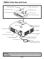
E-10
Names of the Main Unit Parts
POWER
AUTO
MENU
STATUS
POWER
SOURCE
QUICK
MENU
AUDIO
VIDEO
POWER
A
U
TO
M
EN
U
STATUS
PO
W
ER
SOURCE
Q
U
ICK
M
E
N
U
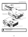
Exhaust
vents
Precautions
The ventilation slots discharge the heat of the lamp and care must be taken not to come into
contact with them.
STATUS indicator [E-61]
POWER button [E-24]
SOURCE button [E-28]
POWER indicator [E-24]
MENU button [E-38]
AUTO button [E-28]
QUICK MENU button [E-32]
Remote control
sensor [E-14]
Front adjuster button [E-27]
(There is also one on the left side.)
Speaker
Exhaust vents
Front adjuster
Remote control sensor
Lens
Focus ring [E-27]
Lens cap
To protect the lens, attach the lens
cap when the projector is not in use.
Ventilation
slots

E-11
Names of the Main Unit Parts
AUT
O
S
OURCE
QUICK
MENU
PC
AUDIO
VIDEO
P
O
W
E
R
AUTO
MENU
STAT
US
POWER
S
O
U
R
C
E
QUICK
MENU
PC
A
U
D
IO
V
ID
E
O
Front adjusters [E-27]
Built-in Security Slot
This security slot supports the MicroSaver Security System manufactured by
Kensington Microware Inc.
AUDIO jack [E-23]
VIDEO jack [E-21, 22]
PC connector [E-18,19,22]
Built-in security slot
(See description below.)
Ventilation slots
AC IN connector [E-24]
Rear adjuster [E-27]
Ventilation slots
Lamp cover [E-67]

E-12
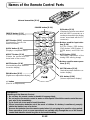
+/– button
(Used in all adjustments)
Names of the Remote Control Parts
ON
OFF
FREEZE
MUTE
PIP
DIGITAL
RGB
YPbPr
VIDEO
S-VIDEO
YCbCr
QUICK
ENTER
ZOOM
VKSTN
HKSTN
CANCEL
MENU
ASPECT
AUTO
POWER
Infrared transmitter [E-14]
ON OFF
FREEZE MUTE PIP
DIGITAL RGB YPbPr
VIDEO S-VIDEO YCbCr
QUICK
ENTER
ZOOM
CANCEL
MENU
ASPECT AUTO
POWER
HKSTN
VKSTN
VOL
F
REEZE button [E-31]
(Freezes moving pictures)
MUTE button [E-31]
(Temporarily cancels the
video and audio)
QUICK button [E-32]
(Displays a simplified menu)
ASPECT button [E-30]
(Selects the vertical and hori-
zontal ratio of the screen)
HKSTN button [E-34]
(Horizontal keystone distortion
correction display)
ZOOM button [E-35]
(Digital zoom adjustment display)
PIP button [E-31]
(Displays the picture associated
with the VIDEO connector as a
smaller picture within the display
screen associated with the PC
connector)
Buttons used for input selec-
tion [E-28]
DIGITAL button, RGB button,
YPbPr button, VIDEO button, S-
VIDEO button, and YCbCr but-
ton
AUTO button [E-29]
(Automatic adjustment of the
analog RGB moving image)
Buttons used for menu opera-
tions [E-37]
VKSTN button [E-34]
(Vertical keystone distortion cor-
rection display)
VOL button [E-36]
(Volume adjustment display)
Precautions
Handling of the Remote Control
* Do not drop the remote control or handle it inappropriately.
* Do not expose the remote control to water or other liquids. Should the remote control become
wet, wipe it dry immediately.
*Try to avoid use in hot and/or humid locations.
* Please keep button batteries out of the reach of children. If a battery is swallowed, promptly
obtain the medical care of a doctor.
* Remove the batteries from the remote control when it is not going to be used for a long period.
* Some operations (such as menu operations) are available only through the use of the remote
control and attention should be given to its careful handling.
POWER button [E-24]

E-13
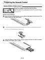
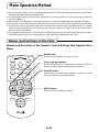
Preparing the Remote Control
Button Battery Replacement
Using the remote control for the first time
The battery compartment is fitted with a transportation insulation sheet at
the time of shipping. Pull out the sheet and remove it. The remote control is
now ready for use.
Replacement Method
1
Insert the tip of a ballpoint pen or some other pointed object into the hole of the
battery holder, then pull out to open.
2
Remove the old battery and install a new button battery with (+) side facing upward in the battery holder.
3
Insert the battery holder into the remote control and push in until the battery
holder closes with a "click" sound.
CR2025
M
n
O
2
-
L
i
C
E
L
L
3
V
O
L
T
S
J
A
P
A
N
H
C
R2025
CR2025
M
n
O
2
-
L
i
C
E
L
L
3
V
O
L
T
S
J
A
P
A
N
H
C
R
20
25
Purchase a CR2025 type battery for replacement.

E-14
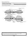
Remote Control Range
Point the infrared transmitter of the remote control toward the remote control sensor located at the front
or rear of the main unit and operate.
Reception of the remote control signal should generally be possible within the range illustrated below.
30˚
30˚
50˚
50˚
4m / 13.1 feet
4m / 13.1 feet
7m / 23 feet
7m / 23 feet
Remote control sensor
Remote control infrared
transmitter
Side View
Remote control
sensor
Remote control infrared
transmitter
Top View
Note
* Exposure of the main unit's remote control sensor or the remote control infrared transmitter to bright light or
the obstruction of the signal by an obstacle located in the pathway may prevent operation.
* The remote control will not function when the battery is exhausted.
Preparing the Remote Control

E-15
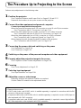
The Procedure Up to Projecting to the Screen
Perform setup adjustments in the following order.
1
Position the projector
See "Projection Distance and Screen Size" on Pages E-16 and E-17.
Determine the locations to set up the screen and the projector.
2
Connect the video equipment and personal computer
Connect your equipment to the projector.
When the personal computer has a DVI connector or a mini D-sub 15-pin connector
See "Connections with PC Connectors" on Page E-18.
When the video equipment has a video connector or an S-video connector
See "Connections with Mini D-Sub 15-Pin Connectors" on Page E-19.
When the video equipment has a YCbCr connector or a YPbPr connector
See "Connections with Component Signals" on Page E-22.
When playing the audio through the built-in speaker of the projector
See "Connections with the AUDIO Jack" on Page E-23.
3
Connecting the power cable and switching on the power
See "Operating" on Page E-24.
See "Finishing" on Page E-25.
4
Switching on the power of the personal computer and video equipment
5
Properly adjust the projection image to the screen
See "Projection Screen Position Adjustment" on Page E-26.
6
Focusing
See "Focus Adjustment" on Page E-27.
7
Selecting input equipment
See "Input Selection" on Page E-28.
8
Adjust the screen or video image
Adjust the image to the optimum condition as required.
See the Table of Contents for the adjustment items.
Note
* Please purchase a screen.
* A DVI-D cable (order code 28-697), which is available separately, is required for connections with the DVI
connector of the personal computer.
* A component cable (order code 28-698), which is available separately, is required to connect a DVD player or
other equipment with YCbCr connectors.
* A component cable (order code 28-690), which is available separately, is required to connect high definition
(HD) video equipment or other equipment with YPbPr connectors.

E-16
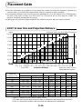
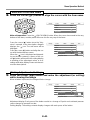
Placement Guide
● Use this information as a guide to find out about the screen size when the projector is placed at a
certain location, or to find out the approximate size of a screen that will be required.
● The projection distance over which focussing is adjustable is 1.2 m (3.9 feet) to 6.9 m (22.6 feet) from
the front of the main unit lens for V-807 and 1.2 m (3.9 feet) to 6.6 m (21.7 feet) for V-1080. The
projector should be placed within this range.
● Please see the projection distance table for the model of projector that you have purchased.
V-807 Screen Size and Projection Distance
0.5(1.6)
1.0(3.3)
1.5(4.9)
2.0(6.6)
2.5(8.1)
3.0(9.8)
3.5(11.5)
4.0(13.1)
0.5
(1.6)
1.0
(3.3)
1.5
(4.9)
2.0
(6.6)
2.5
(8.1)
3.0
(9.8)
3.5
(11.5)
4.0
(13.1)
4.5
(14.8)
5.0
(16.4)
5.5
(18.0)
6.0
(19.7)
6.5
(21.3)
7.0
(23.0)
(m)
(feet)
m (feet)
0
h1
h2
35"
40"
60"
80"
100"
120"
150"
180"
200"
Height from center of lens to
bottom edge of the projection
Height from center of lens to top edge of the projection
Screen Height
17.2˚ Projection angle
Center of lens
Projection Distance
35"
40"
60"
80"
100"
120"
150"
180"
200"
0.710.53
0.810.61
1.220.91
1.631.22
2.021.52
2.441.83
3.052.29
3.662.74
4.063.05
1.20
1.37
2.06
2.75
3.43
4.12
5.15
6.18
6.87
0.64
0.73
1.09
1.46
1.82
2.19
2.74
3.29
3.65
0.11
0.12
0.18
0.24
0.30
0.36
0.45
0.54
0.60
Screen Size
Designation (Inches)
Screen Size Width x Height Projection Distance Height h1 Height h2
* There is a tolerance of ±5% due to design values.
* This table uses the lens apex and lens center as references and requires that the projec-
tor be in a horizontal condition (with front and rear adjusters fully withdrawn).
2.331.74
2.662.00
4.002.99
5.354.00
6.634.99
8.006.00
10.007.51
12.008.99
13.3210.00
(m) (feet)
3.94
4.49
6.76
9.02
11.25
13.52
16.90
20.28
22.54
2.10
2.40
3.58
4.79
5.97
7.19
8.99
10.79
11.98
0.36
0.39
0.59
0.79
0.98
1.18
1.48
1.77
1.97
(m) (feet) (m) (feet) (m) (feet)

E-17
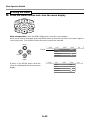
V-1080 Screen Size and Projection Distance
0
h2
h1
0.5(1.6)
1.0(3.3)
1.5(4.9)
2.0(6.6)
2.5(8.1)
3.0(9.8)
3.5(11.5)
4.0(13.1)
0.5
(1.6)
1.0
(3.3)
1.5
(4.9)
2.0
(6.6)
2.5
(8.1)
3.0
(9.8)
3.5
(11.5)
4.0
(13.1)
4.5
(14.8)
5.0
(16.4)
5.5
(18.0)
6.0
(19.7)
6.5
(21.3)
7.0
(23.0)
(m)
(feet)
m (feet)
36"
40"
60"
80"
100"
120"
150"
180"
200"
Height from center of lens to
bottom edge of the projection
Height from center of lens to top edge of the projection
Screen Height
17.2˚ Projection angle
Center of lens
Projection Distance
* There is a tolerance of ±5% due to design values.
* This table uses the lens apex and lens center as references and requires that the projec-
tor be in a horizontal condition (with front and rear adjusters fully withdrawn).
Placement Guide
36"
40"
60"
80"
100"
120"
150"
180"
200"
0.740.55
0.810.61
1.220.91
1.631.22
2.021.52
2.441.83
3.052.29
3.662.74
4.063.05
1.20
1.32
1.99
2.65
3.31
3.97
4.97
5.96
6.62
0.65
0.72
1.07
1.43
1.79
2.14
2.68
3.21
3.57
0.10
0.11
0.16
0.21
0.26
0.31
0.39
0.47
0.52
Screen Size
Designation (Inches)
Screen Size Width x Height Projection Distance Height h1 Height h2
2.431.80
2.662.00
4.002.99
5.354.00
6.634.99
8.006.00
10.007.51
12.008.99
13.3210.00
(m) (feet)
3.94
4.33
6.53
8.69
10.86
13.02
16.31
19.55
21.72
2.13
2.36
3.51
4.69
5.87
7.02
8.79
10.53
11.71
0.33
0.36
0.52
0.69
0.85
1.02
1.28
1.54
1.71
(m) (feet) (m) (feet) (m) (feet)

E-18
Connecting Personal Computers and Video Equipment
● Connecting this unit with a personal computer permits presentation data to be projected as a large
screen display at conferences, lectures, and on other occasions. Furthermore, connecting this unit to
a DVD player or other video equipment source in combination with an audio/video amplifier and speaker
system will allow you to enjoy convincing home theater.
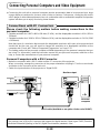
Connections with PC Connectors
Please check the following matters before making connections to the
personal computer.
* Suitable resolution for V-807 is 800 x 600 dots (S-VGA), and the displayable resolution is XGA (1024 x
768 dots).
* Suitable resolution for V-1080 is 1024 x 768 dots (XGA), and the displayable resolution is S-XGA (1280
x 1024 dots).
Note that input of a resolution that exceeds the displayable resolution will cease to be projected and
should this be the case, you will need to change the resolution to a displayable resolution at the
computer side. Check with "Table of Supported Frequencies" on Page E-70.
* The setting method of the personal computer will differ depending on the personal computer that you
are using. For information, read the instruction manual for your personal computer, read the on-line
help, or contact the manufacturer of your personal computer.
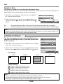
Personal Computers with a DVI Connector
* Make the connection with a DVI-D cable and the PC connector of the projector.
When connecting, arrange the connectors in the proper orientation and plug in. Turn the screw knobs
and fasten to the connector of the main unit.
* Switch the input selection of the projector to "Digital RGB".
PC
VIDEO
AUDIO
Monitor output
Personal
computer
DVI-D cable (Available as an option. Order code: 28-697)
Note
This projector uses a 29-pin DVI connector that supports the digital interface. Digital signal TMDS (Transition
Minimized Differential Signalling) of the DVI (Digital Visual Interface) standard is used.

E-19
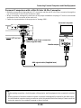
Connecting Personal Computers and Video Equipment
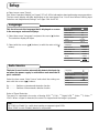
Personal Computers with a Mini D-Sub 15-Pin Connector
* Make the connection to the projector's PC connector and the mini D-sub 15-pin connector through the
use of a DVI/mini D-sub 15-pin conversion cable.
* When connecting, arrange the connectors in the proper orientation and plug in. Turn the screw knobs
and fasten to the connector of the main unit.
* Switch the input selection of the projector to "Analog RGB".
PC
VIDEO
AUDIO
Personal computer
Monitor output
DVI/mini D-sub 15-pin conversion
cable (Supplied item)
RGB signal cable (Supplied item)
Note
* Before making connections, check the power of the projector and the equipment to be connected is switched
off.
* When projection will be with a notebook computer connected, knowledge will be required for the cable connec-
tion and notebook computer startup procedure as well as the operation that follows startup. Please consult the
instruction manual of your notebook computer or the on-line help.

E-20
Connecting Personal Computers and Video Equipment
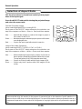
To Output the External Output Signal of a Notebook Computer
When projection will be with a notebook computer connected, knowledge will be required for the cable
connection and notebook computer startup procedure as well as the operation that follows notebook
startup. Please consult the instruction manual of your notebook computer or the on-line help while per-
forming the following procedure.
1
Check whether a signal is being sent from the notebook computer to the projector.
An indication appearing on the liquid crystal display of the notebook computer does not necessarily
mean that an external output signal is being output.
2
Should a sign not be output from the notebook computer, please try the operation described below.
For an IBM PC/AT, DOS/V computer, press the [Fn] key plus any one of the [F1] to [F12] keys. (See
the table below.)
Manufacturer Model Key
akia All computers Fn + F2
COMPAQ ARMADA Series Fn + F4
PRESARIO Series Fn + F3
DELL All computers Fn + F8
FUJITSU All computers Fn + F10
GATEWAY All computers Fn + F3
IBM All computers Fn + F7
NEC All computers Fn + F3
Panasonic All computers Fn + F3
SHARP All computers Fn + F5
SONY All computers Fn + F7
SOTEC All computers Fn + F3
TOSHIBA All computers Fn + F5
Note: Table information is current to June 2001.
Note
When the liquid crystal display of the notebook computer and the projector are displayed at the same time, the
projected image might not be correct even though the liquid crystal display shows a correct indication. Should
this occur, stop the simultaneous display of the notebook computer and try the mode with external output only.
(Try an operation such as that described in aforementioned Step 2 and try closing the liquid crystal panel which
might result in external output only.)
Page is loading ...
Page is loading ...
Page is loading ...
Page is loading ...
Page is loading ...
Page is loading ...
Page is loading ...
Page is loading ...
Page is loading ...
Page is loading ...
Page is loading ...
Page is loading ...
Page is loading ...
Page is loading ...
Page is loading ...
Page is loading ...
Page is loading ...
Page is loading ...
Page is loading ...
Page is loading ...
Page is loading ...
Page is loading ...
Page is loading ...
Page is loading ...
Page is loading ...
Page is loading ...
Page is loading ...
Page is loading ...
Page is loading ...
Page is loading ...
Page is loading ...
Page is loading ...
Page is loading ...
Page is loading ...
Page is loading ...
Page is loading ...
Page is loading ...
Page is loading ...
Page is loading ...
Page is loading ...
Page is loading ...
Page is loading ...
Page is loading ...
Page is loading ...
Page is loading ...
Page is loading ...
Page is loading ...
Page is loading ...
Page is loading ...
Page is loading ...
Page is loading ...
Page is loading ...
-
 1
1
-
 2
2
-
 3
3
-
 4
4
-
 5
5
-
 6
6
-
 7
7
-
 8
8
-
 9
9
-
 10
10
-
 11
11
-
 12
12
-
 13
13
-
 14
14
-
 15
15
-
 16
16
-
 17
17
-
 18
18
-
 19
19
-
 20
20
-
 21
21
-
 22
22
-
 23
23
-
 24
24
-
 25
25
-
 26
26
-
 27
27
-
 28
28
-
 29
29
-
 30
30
-
 31
31
-
 32
32
-
 33
33
-
 34
34
-
 35
35
-
 36
36
-
 37
37
-
 38
38
-
 39
39
-
 40
40
-
 41
41
-
 42
42
-
 43
43
-
 44
44
-
 45
45
-
 46
46
-
 47
47
-
 48
48
-
 49
49
-
 50
50
-
 51
51
-
 52
52
-
 53
53
-
 54
54
-
 55
55
-
 56
56
-
 57
57
-
 58
58
-
 59
59
-
 60
60
-
 61
61
-
 62
62
-
 63
63
-
 64
64
-
 65
65
-
 66
66
-
 67
67
-
 68
68
-
 69
69
-
 70
70
-
 71
71
-
 72
72


PLUS Vision Projector V-807 User manual
- Category
- Data projectors
- Type
- User manual
- This manual is also suitable for
Ask a question and I''ll find the answer in the document
Finding information in a document is now easier with AI
Related papers
-
PLUS Vision V-1100Z User manual
-
-
-
-
-
PLUS Vision PLUS U4-131 User manual
-
-
-
-
Other documents
-
 Commercial Electric 5010-WH Operating instructions
-
Olympus VP--1 User manual
-
-
Toshiba 3LCD User manual
-
-
Plus U5-632 User manual
-
Texas Instruments U5-112 User manual
-
Sharp PG-M15X User manual
-
Christie Roadie HD+35K User manual
-
Runco RS-900 Series RS1100 Series User manual
