Page is loading ...

Split System Indoor Coils for
Installation Instructions
CAUTION:
Read the Installation Instructions
supplied with furnace/air handler and
observe all safety requirements out-
lined in instructions and/or furnace/air
handler markings before proceeding
with installation of the coil
These instructions are primarily intended to
assist qualifi ed individuals experienced in the
proper installation of this appliance. Qualifi ed
installer must have specifi c IQ Drive
TM
system
training. Some local and national codes require
licensed installation/service personnel for this
type of equipment. Read all instructions carefully
before starting the installation.
Systems

2

3
Table of Contents
1. General Information ............................................................................................................... 4
2. Coil Specifi cations ................................................................................................................. 4
3. Coil Installation ....................................................................................................................... 5
• Upfl ow Furnace
• Horizontal Ready Coils for Horizontal Left Installation
• Horizontal Ready Coils for Horizontal Right Installation
4. Refrigerant Line Connections ............................................................................................... 6
5. Completing the Installation ................................................................................................... 7
• Condensate Drain
• Air Filter
• Panels
• Refrigerant Charging
6. Maintenance and Service ...................................................................................................... 7

4
1. GENERAL INFORMATION
IQ™ cased coils are designed for upfl ow ap-
plications or horizontal applications. Coils are
equipped with braze type refrigerant connections
for easy installation.
These coils are equipped with ESX step motor
expansion valve which provides precise fl ow
control for maximum effi ciency and reliability.
The ESX valve is controlled to maintain constant
superheat in a wide range of conditions via a
pressure transducer and a temperature sensor
installed on the coil suction header.
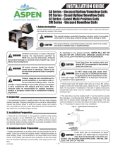
17 1/4
W
H
OW
5/8
20 3/4
HL
HS
Figure 1.
These coils are also equipped with a coil tempera-
ture sensor to monitor coil temperature during
dehumidifi cation mode of system operation.
Read the installation manual supplied with the
outdoor unit for refrigerant line connection pro-
cedure, required line sizes, and other information
pertaining to the system installation.
1. Refer to the Installation Instructions of the
outdoor unit for connection of the additional
components of the IQ drive system.
2. Make certain that the air delivery of the
furnace/air handler is adequate to handle
the static pressure drop of the coil, fi lter, and
duct work.
2. COIL SPECIFICATIONS
Coil Model C6BH (1) E36-B E36-C E48-C E48-D
Nominal Capacity BTUH (2) 36,000 36,000 48,000 48,000
Nominal Airfl ow (CFM) 1,200 1,200 1,600 1,600
W - Width (in.) 17 1/2 21 21 24 1/2
H - Height (in.) 26 3/4 26 3/4 30 1/4 30 1/4
HL - Height of Liquid Line (in.) 23 1/2 23 1/2 27 27
HS - Height of Suction Line (in.) 21 1/2 21 1/2 25 25
Connection - Liquid Line 3/8 3/8 3/8 3/8
Connection - Suction Line 3/4 7/8 7/8 7/8
(1) Refer to sales specifi cation sheets for Listed/Certifi ed combinations of equipment and required accessories.
(2) Refer to the current ARI Directory for certifi ed ratings of split systems.
Table 2. C6 Coil Specifi cations

5
3. Where precise forming of the refrigerant
lines is required, a copper tubing bender
designed for the size lines used is recom-
mended. Avoid sharp bends and contact of
the refrigerant lines with metal surfaces.
4. Refrigerant lines should be wrapped with
pressure sensitive neoprene or other suit-
able material where they pass through the
raw edges of holes.
5. Coil must be level for proper condensate
drainage.
3. COIL INSTALLATION
Upfl ow Furnace —
1. Disconnect all electrical power to the fur-
nace.
2. Remove door and close off plate.
3. Remove the drain pan provided for hori-
zontal application. Install the coil and level
it as needed to ensure proper condensate
drainage. (See Figure 2)
4. Connect the refrigerant lines as outlined in
the Refrigerant Lines section. NOTE: Use
extra care not to damage sensor and
transducer.
5. Route all wires from valve, sensors and
transducer thru the strain relief bushing
(provided) and insert the bushing into the
hole in the close-off plate. Replace the
close-off plate and the door.
6. Use the harness wrap provided to enclose
wires and bring thru the oval opening on
appropriate side of the furnace. Refer to the
wiring diagram provided with the outdoor
section and or gas furnace kit to connect
to valve controller and interface board.
7. Seal the enclosure as required to minimize
air leakage.
Figure 2. Upfl ow Furnace Application
Wires from
Coil
Blower Kit

6
To Confi gure Horizontal Ready Coils for
Horizontal LEFT Installations:
1) Remove the coil access door.
2) IMPORTANT: Remove the plug from one of
the threaded holes in the horizontal drain
pan. Completely remove the webbing located
in the threaded holes of the horizontal drain
pan. If webbing is not removed, the drain will
not function properly and ceiling damage
may occur.
3) Insert a plug (from the horizontal drain pan)
into the open and unused drain hole in the
drain pan at the bottom of the unit to block
bypass air.
4) Remove the corresponding drain line knock-
out from the coil access door to allow access
to the horizontal drain.
5) Replace the door.
To Confi gure Horizontal Ready Coils for
Horizontal RIGHT Installations:
1) Remove the coil access door. Unscrew the
line-set tube close-off plate from the front
left cabinet rail.
2) Slide the coil and drain pan assembly out
of the unit.
3) IMPORTANT: Remove the plug from one of
the threaded holes in the horizontal drain pan.
Completely remove the webbing located in the
threaded holes of the drain pan. If webbing
is not removed, the drain will not function
properly and ceiling damage may occur.
4) Remove the sheet metal hairpin covers
(if supplied) from the back of the coil and
discard.
5) Place the horizontal drain pan on the oppo-
site side of the coil. On units with 2 sets of
knockouts, remove the other set of knockouts
in the coil spacing plates and insert support
rod.
6) Insert a plug (from the horizontal drain pan)
into the open and unused drain hole in the
drain pan at the bottom of the unit to block
bypass air.
7) Slide the coil and the horizontal drain pan
assembly back into the unit. Reattach the
tube close off plate.
8) Remove the corresponding drain line knock-
out from the coil access door to allow access
to the horizontal drain.
9) Replace the door.
Note: All condensate pans have primary and
secondary drain connections to meet FHA
requirements. If the application is located in
or above a living space where damage may
result from condensate overfl ow, a separate
3/4 inch drain must be provided from the
secondary drain connection and a secondary
drain pan must be installed under the entire
unit. Run secondary drain lines to a place
where they are noticeable if used.
4. REFRIGERANT LINE
CONNECTIONS
Line Connections:
1. Remove the protective caps from the coil
and refrigerant line set and also remove the
hole grommets and tube close-off insulation
from around the tubes.
2. Cut the line set tubing to the proper length.
Be sure that the tubing has been sized in
accordance with the outdoor unit specifi ca-
tions.
3. Inspect both refrigerant lines. The ends of
the lines must be round, clean, and free of
any burrs.
4. Insert the line set tubes into the coil tube
stubs until they bottom out.
5. Braze the individual connections with dry
nitrogen fl owing through the joints to elimi-
nate internal oxidation and scaling.
CAUTION:
It is recommended to wrap a wet rag
around both the pressure transducer
and sensor while brazing to prevent
damage to these components unique
to the IQ Drive
TM
System.
6. Check the assembly for leaks with dry
nitrogen.
7. On horizontal applications re-position the
sensing bulb on the suction line so it is in
the 4 o'clock or 8 o'clock position on the
suction tube.
NOTE: Sensor bulb must be secure and
insulated.

7
5. COMPLETING THE
INSTALLATION
Condensate Drain:
CAUTION:
The indoor coil must be checked to
ensure a level installation. Failure to do
so may result in improper condensate
disposal, causing structural damage,
premature equipment failure, or pos-
sible personal injury.
1. The coil condensate pan is furnished with
3/4" NPSC drain connections. Use a PVC
or similar material fi tting to attach the drain
line to the pan. The fi tting should be hand
tightened only. Overtightening may crack
the drain pan and cause a condensate
leak.
2. Connect the drain line and run to a suitable
drain avoiding sharp bends and pinching of
the line. Install a condensate trap and prime
with water.
3. During the system checkout, inspect the
drain line and connections to verify proper
condensate disposal.
Air Filter — Air fi lters are not provided as an
integral part of this coil, however, a fi lter must
be installed upstream of the coil and inspected
frequently. When the fi lter becomes clogged with
dust or lint, it should be replaced (disposable type)
or cleaned (washable type). The fi lter should be
inspected and replaced or cleaned at least twice
during the year, generally at the start of each
heating and cooling season.
Panels — Reinstall all inner and outer panels of
the coil case and furnace that were previously
removed.
Refrigerant Charging — These cased indoor
coils are not factory charged with refrigerant.
It will be necessary to evacuate the indoor coil
and line set prior to charging. Refer to the outdoor
unit installation manual for detailed charges and
instructions.
6. MAINTENANCE AND SERVICE
WARNING:
Ensure that all electrical power to the
furnace and outdoor (condensing) unit
is off before performing any mainte-
nance or service on the system.
To ensure optimum performance and to mini-
mize possible equipment failure, the following
periodic maintenance should be performed on
this equipment:
1. The air fi lter installed with the system should
be checked and cleaned or replaced twice
per year.
2. Check the coil, drain pan, and condensate
drain line for cleanliness at the start of
each heating and cooling season. Clean as
needed.
CAUTION:
Do not operate the system without hav-
ing a suitable fi lter in place in the return
air duct system. Always replace the
fi lter with the same size and type.

INSTALLER: PLEASE LEAVE THESE
INSTALLATION INSTRUCTIONS WITH
THE HOMEOWNER
7088940
Specifi cations and illustrations subject to change
without notice and without incurring obligations.
Printed in U.S.A. (03/08)
¢708894Y¤
7088940
/