Page is loading ...

iConverter
®
Gx AN Plug-in Module QUICK START GUIDE
The Omnitron iConverter Gx AN Plug-In media converter provides 1000BASE-T Copper
to 1000BASE-X ber media conversion.
The Gx AN can be used to connect Gigabit le servers to Gigabit
switches and connect switches with Gigabit ber uplinks.
The Gx AN supports auto-negotiation with congurable Full/Half
Duplex mode via hardware and software controls.
The Gx AN plug-in module can be managed using Omnitron’s
NetOutlook
®
SNMP Management Software, 3rd Party SNMP Client,
or with a Network Management Module (NMM2) via Telnet or the
Command Line Interface (CLI).
For more information, including the complete User Manual on the
Gx AN Plug-in module, access Omnitron’s documentation download
web page to view all relevant documents:
https://www.omnitron-systems.com/documentation
INSTALLATION PROCEDURE
1) Congure DIP-Switches
2) Install Module in Chassis and Connect Cables
3) Verify Operation
1) CONFIGURE DIP-SWITCHES
SW1 - Port 1 Auto/Manual Negotiation “AN MAN”
When this DIP-switch is in the Auto-Negotiate “AN” position (factory default), the ber
optic port is transparent to the network and allows the end devices connected to the
module to advertise through the module and
establish negotiated settings between the end
devices. If Port 2 (RJ-45) is not connected, the
ber port will not be able to establish a ber link.
In the AN mode, the DIP-switches for Pause, Port 2
(RJ-45) and link modes RFD and SFD are ignored.
If two Gx AN modules are linked together and Port
1 is congured for auto-negotiation, the mode
of operation will be determined by the devices
connected to Port 2 (RJ-45). Port 1 is transparent
to the process.
When this DIP-switch is in the Manual “MAN”
position, the advertised auto-negotiation
capabilities of Port 2 is controlled by DIP-switches
SW2 through SW5.
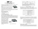
Left
Switch 1
Switch 8
Right
Figure A: DIP-Switch Locations
Page 1
Switch
Left
(Factory Default)
Right
SW1 P1 AN:
Port 1
Fiber Auto-negotiation
P1 MAN:
Port 1
Fiber Manual negotiation
SW2 -SW3 Port 2 (P2) advertised auto-negotiation capability - See Figure C
SW4 - SW5 Pause Advertisement Mode - See Figure D
SW6 - SW8 Link Modes - See Figure E
Figure B: DIP-Switches
SW2 and SW3 - Port 2 (UTP) Settings “AN MAN” “FDX HDX”
These DIP-switches are only valid when Port 1 is set to “MAN”. Port 2 is always
congured for auto-negotiation and DIP-switches SW2 and SW3 dene what modes
are advertised by auto-negotiation. See Figure C: Port 2 (RJ-45) Modes.
SW2 SW3 Port 2 (RJ-45) Mode of Operation
Left Left
Congured for Auto-Negotiation
It advertises and negotiates in this order:
1000FDX, 1000HDX
Right Left
Congured for Auto-Negotiation
It advertises and negotiates in this order:
1000FDX
Left / Right Right
Congured for Auto-Negotiation
It advertises and negotiates in this order:
1000HDX
Figure C: Port 2 (RJ-45) Modes
SW4 and SW5 - Port 2 Pause Advertisement “OFF PAUSE” “OFF ASYM”
These DIP-switches are only valid when Port 1 is set to “MAN”. The PAUSE modes
advertised by auto-negotiation will be based on the conguration of DIP-switches SW4
and SW5.
SW4 SW5 Port 2 (RJ-45) Pause Modes
Left Left No PAUSE advertised
Left Right Asymmetric PAUSE towards link partner
Right Left Symmetric PAUSE
Right Right
Both Symmetric and Asymmetric PAUSE
towards local device
Figure D: Pause Modes
SW6, SW7, SW8 - Link Modes
These three DIP-switches congure the link mode settings. DIP-switch SW6 is valid when
Port 1 is set to “AN” or “MAN”. DIP-switches SW7 and SW8 are ignored when Port 1 is
set to “AN”. The following table details possible Link Mode DIP-switch congurations.
Page 2

SW1 SW6 SW7 SW8 Results
Left
(AN)
Left Left Left Enables Link Segment mode (LS AN)
Left
(AN)
Right Left Left Enables Link Propagate mode (LP AN)
Right
(MAN)
Left Left Left Enables Link Segment mode (LS MAN)
Right
(MAN)
Right Left Left Enables Link Propagate mode (LP MAN)
Right
(MAN)
Left Right Left
Enables Remote Fault Detection mode + Link
Segment (RFD+LS)
Right
(MAN)
Right Right Left
Enables Remote Fault Detection mode + Link
Propagate (RFD+LP)
Right
(MAN)
Left Left Right Enables Symmetrical Fault Detect mode (SFD)
Right
(MAN)
Right Left Right Undened
Right
(MAN)
Left Right Right Undened
Right
(MAN)
Right Right Right Undened
Figure E: Link Modes Table
NOTE: Connecting two converters set to any of the RFD modes is illegal and will
cause a “deadly embrace” lockup.
NOTE: It is recommended to keep the LS setting (default) until initial conguration
is complete.
For detailed information on the operation of the different Link Modes, download the
application note “iConverter Link Modes” available on Omnitron’s web page:
https://www.omnitron-systems.com/documentation
Page 3
2) INSTALL MODULE IN CHASSIS AND CONNECT CABLES
a. Carefully slide the module into an open slot in the chassis. Align the module with
the installation guides and ensure that the module is rmly seated against the
backplane. Secure the module by fastening the front panel thumbscrew (push in and
turn clockwise to tighten) to the chassis front. Verify the “Pwr” LED is ON (indicating
the chassis is powered).
b. When using a Gx AN SFP model, insert the SFP Fiber transceiver into the Port 1
SFP receptacle on the Gx AN.
NOTE: The release latch of the SFP Fiber transceiver must be in the closed
position before insertion.
c. Connect the RJ-45 port via a Category 5 cable to a 1000BASE-T Ethernet device.
d. Connect an appropriate multimode or single-mode ber cable to the ber port of the
installed module. It is important to ensure that the transmit (TX) is attached to the
receive side of the device at the other end and the receive (RX) is attached to the
transmit side. Single-ber (SF) media converter models operate in pairs. The TX
wavelength must match the RX wavelength at the other end and the RX wavelength
must match the TX wavelength at the other end
3) VERIFY OPERATION
Once the module has been installed and congured, per steps 1 and 2, verify the module
is operational by viewing the status of the LED indicators. The table below provides a
description for each LED indicator.
The Power LED indicates the module is receiving power from the chassis.
The Fiber Optic “P1” LED indicates the ber optic connection between the modules has
been established. A blinking LED indicates the presence of data, an auto-negotiation
problem or a link mode error indication.
The RJ-45 LEDs indicate the module has established a connection across its RJ-45
port. A blinking LED indicates the presence of data.
LED Function
“Legend”
Color OFF State ON / Blinking State
Power “Pwr” Green No Power ON: Module has power
Fiber Port
“P1”
Green No Fiber Link
ON: Fiber Link
Blinking: Fiber Data Activity
Slow Blinking: Signal detect but auto-negotiation
has not completed or SFD error detected
RJ-45 Port
Duplex Mode
“FDX”
Green
Half-Duplex when P2
link is active
ON: When the RJ-45 link is active and negotiated
to Full-duplex
RJ-45 Port
“P2”
Green Not Linked
ON: RJ-45 linked at 1000Mbps
Blinking: RJ-45 Data Activity
Slow Blinking: SFD error detected
Figure F: LED Indicators
Form 040-8500N-001E 03/17
Omnitron Systems Technology 38 Tesla, Irvine, CA 92618
949.250.6510 tel * 949.250.6514 fax * www.omnitron-systems.com
/