to Symmetrical Pause, Asymmetrical Pause or No Pause mode. When the UTP port
is operating in Manual mode, Pause is disabled.
SW5 - UTP 10/100 AUTO/MANUAL CROSSOVER “AX/MANX”
The 10/100 Auto Crossover feature is
only available when the UTP port is
operating in 10/100 Auto-Negotiation
mode.
When “AX/MANX” DIP-switch is set to
“AX” (factory default), the 10/100 UTP
Auto Crossover feature is enabled.
When it is set to “MANX”, the UTP
Manual Crossover DIP-switch is
enabled to allow the user to manually
set either a Crossover or Straight-through connection.
SW6 - UTP MANUAL CROSSOVER “=/X”
When this DIP-switch is set to “MANX”, the UTP Manual Crossover Switch is enabled.
Set this DIP-switch to “=” (factory setting) when connecting the UTP port to a workstation,
or set it to “X” when connecting to a hub or switch. Only use this setting in 10/100Mbps
Manual negotiation mode.
SW4, SW7, SW8 - RESERVED
These DIP-switches are for factory use only and must always remain in the LEFT
position (factory default).
2) INSTALL MODULE IN CHASSIS AND CONNECT CABLES
a. The GX/TM Network Interface Device (NID) is available in tabletop and wall-mounting
models. For wall-mounting, attach the NID to a wall, backboard or other flat surfaces.
For tabletop installations, place the unit on a flat level surface. Attach the rubber
feet to the bottom of the NID to prevent the unit from sliding. Make sure the unit is
placed in a safe, dry and secure location.
To power the unit using the AC/DC adapter, connect the AC/DC adapter to the AC
outlet. Then connect the barrel plug at the end of the wire on the AC/DC adapter to
the 2.5mm DC barrel connector (center-positive) on the chassis. Confirm that the
unit has powered up properly by checking the power status LED located on the
front of the unit.
To power the unit using a DC power source, prepare a power cable using a two-
conductor insulated wire (not supplied) with a 14 AWG gauge minimum. Cut the
power cable to the length required. Strip approximately 3/8 of an inch of insulation
from the power cable wires. Connect the power cables to the unit by fastening the
stripped ends to the DC power connector.
Connect the power wires to the DC power source. The Power LED should indicate
the presence of power.
WARNING: Note the wire colors used in making the positive and negative
connections. Use the same color assignment for the connection at the DC
power source.
NOTE: If mounting with a safety ground attachment, use the safety ground
screw at the rear of the unit.
b. When using a GX/TM SFP model (8939-0), insert the SFP Fiber transceiver into
the Port 1 SFP receptacle on the GX/TM.
NOTE: The release latch of the SFP Fiber transceiver must be in the closed
SW3 - UTP SPEED GIGABIT/10-100 “1000/10-100”
When the “1000/10-100” DIP-switch is in the “1000” position (factory default), the
UTP port always operates in 10/100/1000Mbps Auto-Negotiation mode. The UTP
port auto-negotiates to a speed of 10Mbps, 100Mbps or 1000Mbps with the
connected UTP device. In this mode, the UTP “AN/Man” and UTP “100/10” DIP-switches
have no effect.
When the “1000/10-100” DIP-switch is in the “10-100” position and the UTP “AN/Man”
DIP-switch is in the “Man” position, the UTP port operates at the Speed, Duplex and
Pause modes set by the “100/10”, “FDX/HDX” and “Off/Pause” DIP-switches.
When the “1000/10-100” DIP-switch is in the “10-100” position and the UTP “AN/Man”
DIP-switch is in the “AN” position, the UTP port maximum auto-negotiation setting
for the Speed, Duplex and Pause mode is determined by the “100/10,” “FDX/HDX”
and “Off/ Pause” DIP-switches.
SW4 - UTP 100/10MBPS “100/10”
When the UTP “AN/Man” DIP-switch (described above) is in the manual “Man” position,
the “100/10" DIP-switch determines the speed of operation for the UTP port. Set the
“100/10” DIP-switch to match the speed of the connected UTP device.
SW5 - UTP FULL/HALF DUPLEX “FDX/HDX”
Setting the UTP Full/Half-Duplex DIP-switch to the UTP “FDX” position (factory default)
forces the UTP port to operate in Full-Duplex. Setting this DIP-switch to UTP “HDX”
forces the UTP port to operate in Half-Duplex. Adjust the UTP Full/Half-Duplex DIP-
switch to match the duplex mode of the connected UTP device.
SW6, SW7, SW8 - LINK MODES
These three DIP-switches configure the link mode settings. The following table details
possible Link Mode DIP-switch configurations.
Switch Down
(Factory Default)
Up SW6 SW7 SW8 Link Mode Selection
SW1 AN:
Fiber Auto-Negotiation
Man:
Fiber Manual Negotiation
Down Down Down Link Segment (LS)
(Factory Default)
SW2 AN:
UTP Auto-Negotiation
Man:
UTP Manual
Up Down Down Link Propagate (LP)
SW3 1000:
UTP 1000Mbps
10-100:
UTP 10-100Mbps
Down Up Down Remote Fault Detect + Link
Segment (RFD + LS)
SW4 100:
UTP 100Mbps
10:
UTP 10Mbps
Up Up Down Remote Fault Detect + Link
Propagate (RFD + LP)
SW5 FDX:
UTP Full-Duplex
HDX:
UTP Half-Duplex
Down Down Up Symmetrical Fault Detect (SFD)
SW6
See Link Mode Selection
Up Down Up Illegal Setting
SW7 Down Up Up Illegal Setting
SW8 Up Up Up Illegal Setting
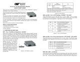
Figure B: DIP-Switch Bank 1
DIP-SWITCH BANK 2
SW1, SW2 - NOT VISIBLE
SW3 - PAUSE DISABLE/ENABLE “OFF/PAUSE”
When the UTP port is operating in Auto-Negotiation mode, it advertises for Pause
based on the Pause Disable/Enable “Off/Pause” DIP-Switch setting. Setting the Pause
DIP-switch to the “Off” position (factory default) forces the UTP port to negotiate to No
Pause. Setting this DIP-switch to the “Pause” position allows the UTP port to negotiate
witch Down (Factory Default) Up
SW3 Off:
Pause Disable
Pause:
Pause Enable
SW4 Reserved Reserved
SW5 Auto:
UTP Auto Crossover
Man:
UTP Manual Crossover
SW6 =:
Manual UTP Straight-Through
X:
Manual UTP Crossover
SW7 Reserved Reserved
SW8 Reserved Reserved
Figure C: DIP-Switch Bank 2