Page is loading ...

WMT900
INSTALLATION INSTRUCTIONS:
1. Connect Modbus RTU bus as labeled in the above diagram.
2. Connect 12-24 VAC/DC power as labeled in the above diagram.
3. Red power Led should light up.
4. Adjust dip switch for desired operation.
5. Perform a local download on the remote Modbus RTU site.
6. Verify the Rf network communication with the Signal Strength, TX, RX, and Link led indicators.
7. Lastly, perform a commission at the base station site to establish the link with the remote location.
Note: As with any Rf network, plan ahead for antenna location and placement. It is the intention of AIC Wireless to provide a
reliable wireless communication device for existing Modbus RTU networks. However, in some conditions, reliability is deter-
mined largely by correct antenna placement, which is the responsibility of the installer. Using good judgment in antenna place-
ment will help decrease service related issues and increase reliability. This product is NOT TO BE USED in situations where life
safety issues may arise. AIC Wireless makes no claims, expressed or implied, of the products usefulness with regard to spe-
cific applications. Determination of the product’s suitability for an application is the sole responsibility of the purchasing par-
ties. In any installation application, ensure devices are properly protected from the elements by installing in appropriate enclo-
sure. Additional surge protection devices may be necessary to protect from lightning/power surges.
The WMT900 is a device designed to transport Modbus RTUcommunication data over short to extended ranges using the 900
MHz frequency (902-928). The WMT900 is designed to be plug-and-play, requiring no special programming tools. Using a
simple software tool (provided) radios can be addressed to one another in the field. See below for installation instructions and
configuration.
Designed and Engineered by AIC, LLC/AIC Wireless
Sylvester, Georgia 31791
US Patent Pending #60/834,471
No reproduction without expressed written consent of AIC, LLC
Operating Voltage: 12-24 VAC/DC (not polarity sensitive)
Power Consumption at Max Power: 1.2A @ 12VAC/DC
* WARNING: If using AC power option, 24 VAC isolation transformer must
be used! Ensure neither of the two secondaries are bonded.
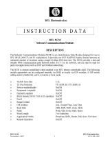
Signal StrengthChannel No.
Ant. Conn. PWR 12-24 VAC/DCDip SwitchesRJ45 Conn.
PWR Link RX TX
Modbus
Antenna RPSMA Connector
PWR Power LED
Link Link between Server/Client
RX Receive Indicator
TX Transmit indicator
Dip Switch WMT900 settings (see installation instructions)
Channel Channel Indicator
Signal Str. Signal Quality Indicator—Red to Green (0-100%)
Modbus in Three wire Modbus RTU termination
PWR 12-24VAC/DC * see Warning
GND 12-24VAC/DC * see Warning

For Support Information, contact AIC Wireless at 229-776-2510,
or e-mail support@aic-wireless.com.
For Sales Information, contact AIC Wireless at 229-776-2510, or
e-mail sales@aic-wireless.com.
FCC ID: R4N-AW900M
IC:5303A-AW900M
This device complies with Part 15 of the FCC rules. Operation is subject
to the following two conditions: (1) This device may not cause harmful
interference; (2) This device must accept any interference received,
including interference that may cause undesired operation.
Dip Switch Definitions For All W*T Products by AIC Wireless
SW1 On (Channel 1 On) SW1 Off (Channel 1 Off)
SW2 On (Channel 2 On) SW2 Off (Channel 2 Off)
SW3 On (Channel 4 On) SW3 Off (Channel 4 Off)
SW4 On (Channel 8 On) SW4 Off (Channel 8 Off)
SW5 Leave in Off Position
SW6 Leave in Off Position
SW7 and SW8 must work in combination.
SW7 On and SW8 Off Ethernet port communication to the radio. Used for programming of the radio server or client radio relationship.
SW7 Off and SW8 Off Ethernet port communication to the device server. Used for programming the device server based on the RS485 baud rate.
SW7 On and SW8 On No function. DO NOT OPERATE IN THIS MODE.
SW7 Off and SW8 On Normal operating mode between the device server and the radio.
SW9 FACTORY USE ONLY, leave in Off position
SW10 On Server Mode SW10 Off Client Mode
There are 12 selectable channels available by combining SW1 through SW4. (Example SW2 On [CH2} and SW3 On [CH4] = Channel 6)
900 MHz Channel Table
Channel Dip Switch Setting Center Frequency
1 1 On/2 Off/3 Off/4 Off 903.12500 MHz
2 1 Off/2 On/3 Off/4 Off 905.20833 MHz
3 1 On/2 On/3 Off/4 Off 907.29167 MHz
4 1 Off/2 Off/3 On/4 Off 909.37500 MHz
5 1 On/2 Off/3 On/4 Off 911.45833 MHz
6 1 Off/2 On/3 On/4 Off 913.54167 MHz
7 1 On/2 On/3 On/4 Off 915.62500 MHz
8 1 Off/2 Off/3 Off/4 On 917.70833 MHz
9 1 On/2 Off/3 Off/4 On 919.79167 MHz
10 1 Off/2 On/3 Off/4 On 921.87500 MHz
11 1 On/2 On/3 Off/4 On 923.95833 MHz
12 1 Off/2 Off/3 On/4 On 926.04167 MHz
Device Server Configuration/Programming:
In the event it is necessary to change factory settings for the Modbus RTU device network, please refer to the WMT900 Device Sever
Programming Guide.
/