Page is loading ...

HEA_ & COOLiING
50JS, 50JX
Single-Packaged Heat Pump Units
Visit www.carfier.com
Installation, Start-Up,
and Service Instructions
NOTE: Read the entire instruction manual before starting the
installation.
TABLE OF CONTENTS
SAFETY CONSIDERATIONS ..................................................... 1
INTRODUCTION .......................................................................... 2
RECEIVING AND INSTALLATION .......................................... 2
Cheek Equipment ...................................................................... 2
IDENTIFY UNIT ................................................................ 2
INSPECT SHIPMENT ........................................................ 2
Provide Unit Support ................................................................ 2
ROOF CURB ....................................................................... 2
SLAB MOUNT ................................................................... 2
GROUND MOUNT ............................................................ 2
Provide Clearances .................................................................... 2
Rig and Place Unit .................................................................... 2
INSPECTION ...................................................................... 2
INSTALLATION ................................................................ 2
Select and Install Ductwork ..................................................... 4
CONVERTING HORIZONTAL DISCHARGE UNITS TO
DOWNFLOW (VERTICAL) DISCHARGE UNITS ......... 5
Provide for Condensate Disposal ............................................. 6
Install Electrical Connections ................................................... 7
HIGH-VOLTAGE CONNECTIONS ................................ 10
ROUTING POWER LEADS INTO UNIT ...................... l0
CONNECTING GROUND LEAD TO GROUND LUG.10
ROUTING CONTROL POWER WIRES (24-V) ............ 13
SPECIAL PROCEDURES FOR 208-V OPERATION ...15
PRE-START-UP .......................................................................... 17
START-UP ................................................................................... 17
Check for Refrigerant Leaks .................................................. 17
Start-Up Adjustments .............................................................. 17
CHECKING COOLING AND HEATING
CONTROL OPERATION ................................................. 17
CHECKING AND ADJUSTING REFRIGERANT
CHARGE ........................................................................... 18
REFRIGERANT CHARGE .............................................. 18
NO CHARGE .................................................................... 18
LOW CHARGE COOLING ............................................. 19
TO USE COOLING CHARGING CHARTS .................. 19
INDOOR AIRFLOW AND AIRFLOW ADJUST-
MENTS .............................................................................. 19
MAINTENANCE ......................................................................... 20
Air Filter. ................................................................................. 21
Indoor blower and motor ........................................................ 21
OUTDOOR COIL, INDOOR COIL, AND
CONDENSATE DRAIN PAN .............................................. .22
Outdoor fan ............................................................................. 23
Electrical controls and wiring ................................................ 23
Refrigerant circuit ................................................................... 24
Indoor airflow ......................................................................... 25
Metering device ...................................................................... 25
Liquid line strainers ................................................................ 25
High Flow Valves ................................................................... 25
Time-delay relay ..................................................................... 25
Loss of charge switch ............................................................. 25
Check defrost thermostat ........................................................ 25
Defrost Thermostat ................................................................ _25
TROUBLESHOOTING .............................................................. .25
START-UP CHECKLIST ............................................................ 25
NOTE TO INSTALLER -- READ THESE INSTRUCTIONS
CAREFULLY AND COMPLETELY before installing this unit.
Also, make sure the Owner's Manual and Service Instnu:tions are
leR with the unit after installation.
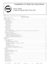
Fig. 1--Model 50JS/50JX
C99001
SAFETY CONSIDERATIONS
Installation and servicing of air-conditioning equipment can be
hazardous due to system pressure and electrical components. Only
trained and qualified personnel should install, repair, or service
air-conditioning equipmenL
Untrained personnel can perform basic maintenance functions of
cleaning coils and filters. All other operations should be performed
by trained service personnel. When working on air-conditioning
equipment, observe precautions in the literature, tags, and labels
attached to the unit, and other safety precautions that may apply.
Follow all safety codes. Wear safety glasses and work gloves. Use
quenching cloth for unbra_ng operations. Have fire extinguisher
available for all brazing operations.
Manufacturer reserves the right to discontinue, or change at any time, specifications or designs without notice and without Incurring obligations.
PC 10t CaLalog No. 5354)0079 Pdn_d in U.S.A_ Form 50JS,JX-SSI Pg 1 Replaces: 50JS,JX_SI

Improper installation, adjustment, altoration, service, mainte-
nance, or use can cause explosion, tire, electric shock, or
other occurrences, winch could cause serious injury or death
or damage your property. Consult a qualified installer or
service agency for information or assistance. The qualified
installer or agency must use only factory-authorized kits or
accessories when modifying this product.
Recognize safety information. This is the safety-alert symbolz_ x .
When you see this symbol on the product or in instructions or
manuals, be alert to the potential for personal inju_.
Understand the signal words -- DANGER, WARNING, CAU-
TION, and NOTE. Danger identifies the most serious hazards,
which will result in severe personal injury or death. Warning
indicates a condition that eolld cause serious personal injury or
death. Caution is used to identify unsafe practices, which would
result in minor personal injury or product and property damage.
NOTE is used to highlight suggestions which will result in
enhanced installation, reliability, or operation.
1. The power supply (volts, phase, and hertz) must correspond to
that specified on unit rating plato.
2. The electrical supply provided by the utility mnst be sufl']cient
to handle load imposed by this unit.
3. Tins installation must conform with local building codes and
with NEC (National Electrical Code). Refer to provincial and
hieal plumbing or wasto water codes and other applicable local
codes.
m kVl=5_1_ff[_
Before performing service or maintenance operations on
system, turn off main power to unit. Turn off accessory heater
power switch if applicable. Electrical shock could cause
severe injury or death.
INTRODUCTION
The 50JS and 50JX heat pumps are fully self-contained and
designed for outdoor installation (See Fig. I). Standard units are
shipped in a horizontal-discharge configuration for installation on
a ground-level slab. Units can be converted to downflow (vertical)
discharge configurations for rooftop applications.
RECEIVING AND INSTALLATION
Step l_heck Equipment
IDENTIFY UNIT
The unit model number and serial number are stamped on the unit
identification plate. Check this information against shipping pa-
pers.
INSPECT SHIPMENT
Inspect for shipping damage while unit is still on shipping pallet.
If unit appears to be damaged or is torn loose from its anchorage,
have it examined by transportation inspectors before removal.
Forward claim papers directly to transportation company. Manu-
facturer is not responsible for any damage incurred in transit.
Check all items against shipping list. Immediately notify the
nearest Cartier Air Conditioning office if any item is missing. To
prevent loss or damage, leave all parts in original packages until
installation.
Step 2---Provide Unit Support
ROOP CURB
Install accessory roof curb in accordance with instructions shipped
with curb (See Fig. 5). Install insulation, cant strips, roofing, and
flashing. Ductwork must be attached to curb.
IMPORTANT: The gaskcting of the unit to the roof curb is critical
for a watertight seal. Install gasketing material supplied with the
ronf curb. Improperly applied gaskcting also can result in air leaks
and poor unit performance.
Curb should be level to within 1/4 in. (See Fig. 6). This is
necessary for unit drain to function properly. Refer to accessory
roof curb installation instructions for additional information as
required.
SLAB MOUNT
Place the unit on a solid level concrete pad that is a minimum of
4 in. thick with 2 in. above grade (See Fig. 7). The slab should
extend approximately 2 in. beyond the casing on all 4 sides of the
unit. Do not secure the unit to the slab except when required by
local codes.
GROUND MOUNT
The unit may be installed either on a slab or placed directly on the
ground if local codes permit. Place the unit on level ground
prepared with gravel for condensate discharge.
Step 3_Provide Clearances
The required minimum service clearances are shown in Figs. 2 and
3. Adequate ventilation and outdoor air must be provided. The
outdoor fan draws air through the outdoor coil and discharges it
through the top fan grille. Be sure that the fan discharge does not
recirculato to the outdoor coil. Do not locate the unit in either a
corner or under an overhead obstruction. The minimum clearance
under a partial overhang (such as a normal house overhang) is 36
in. above the unit top. The maximum horizontal extension of a
partial overhang must not exceed 48 in. For extended overhangs,
provide a minimum clearance of 48 in.
IMPORTANT: Do not restrict outdoor airflow. An air restriction
at either the outdoor-air inlet or the fan discharge may be
detrimental to compressor life.
Do not place the unit where water, ice, or snow from an overhang
or roof will damage or flood the unit. Do not install the unit on
carpeting or other combustible materials. Slab-mountod units
should be at least 4 in. above the highest expected wator and nmoff
levels. Do not use unit if it has been under water.
Step 4-_Rig and Place Unit
Rigging and handling of this equipment can be hazardous for many
reasons due to the installation location (roofs, elevated stmctures_
etc.)
Only trained, qualified crane operators and ground support staff
should handle and install this equipment.
When working with this equipment, observe precautions in the
literature, on tags, stickers, and labels attached to the equipment,
and any other safety precautions that might apply.
Follow all applicable safety codes. Wear safety shoes and work
gloves.
INSPECTION
Prior to initial use, and at monthly intervals, all rigging brackets
and straps should be visually inspected for any damage, evidence
of wear, structural deformation, or cracks. Particular attention
should be paid to excessive wear at hoist hooking points and load
support areas. Brackets or straps showing any kind of wear in these
areas must not be used and should be discarded.
INSTALLATION
1. Remove unit from shipping carton. Leave top shipping skid on
the unit as a spreader bar to prevent the rigging straps from
damaging the unit. If the wood skid is not available, use a
spreader bar of sufficient length to protect unit from damage.

_" TOP VIEW
,,,,,,,,,,
BIIIIIIIII lilllil
_PPLI
402 _UCT _uCl
i I
sa )
t3,B_ REAR VIEW
U (12.qk_iCS llD m MAll.
MILLI_T[R$ [IN)
TOP _ UNIT ............................................. 355.5 114.0©]
DUCT Sip[ _ UNll ...................................... 50_ (20€)
SIDE _'PO$1T[ OUSTS ..................................... )5_.5 114 0_)
_TT_I OF UNIT ........................................ 1_.7 (0.50)
[L(CTRIC HEAT PAH[L ..................................... tl44 [)500)
i_ _ Ct.F.AJiJaEl_
MILLIMETERS tINT
B[TWE[N UNITS, POId_ ENTRy SI_ ............... 1066 $ 142 00]
UNiT kid UNGNOUND[O SURFACES, pOllER [HTRY _1[*[ .......... gl4.0 (35.001
IIN_I AND BLOCKOH C_ICRET[ _kLLS ANO OTHER
GNOUN_D SURIA_[S, _ONER [HTRT SIb[ ........... 1066 $ [4_ 00]
_ CI BII_M_CE _OR oqmAllm MK) _
MILLIM[TERS tIN)
[VkP COIL ACCESS SIDE ................................ 9140 (3600)
PIeR ENTR? SlOE ................................ 914 _ (36 00]
([X¢[P1 F_ HE€ II{OUIItEME#TSI
UNIT l_ ............................................... 914 0 (35 0_]
$10( O_I_SIT[ OUCT$.............................. 914¸0 (_5 0_)
OUI_T PANEL.............................................. )04¸8 [12.00)1
*MINIMUM _ISTANC[S:IF UNIT IS PLAC[O L[$$ THAN 304.8 [IZ.O4) _RO_ WALL
_TSTEW,TH[H S_ST_II PERFORNkNCE NATBE C_PRI'IIIS[D
DIMENSIONS IN [) ARE IN INCHES
UNIT
50JS018
50JS024
5OJS03O
50JS036
50JS042
50JX024
5OJX030
50JXO36
13 43)
II1!111III II I IIIli
l,l llllllll+
L'? ,=
----se
(0201
RIGHT gDE VIEW
UNIT WEIGHT UNIT HEIGHT
ELECTRICAL CHARACTERISTICS IN. (MM)
Ib kg "A"
208/230-1-60 283 128.4 37.02 (940.3)
208/230-1-60 289 131.1 39.02 (991.1)
208/230-1-60, 208/230-3-60 287 130.2 39.02 (991.1)
208/230-1-60, 208/230-3-60, 460-3-60 291 132.0 37.02 (940.3)
208/230-1-60, 208/230-3-60, 460-3_0 323 146.5 37.02 (940.3)
208/230-1-60 299 135.6 41.02 (1041.9)
208/230-1-60, 208/230-3-60 320 145.2 37.02 (940.3)
208/230-1-60, 208/230-3-60, 460-3-60 328 148.8 37.02 (940.3)
X
19.5 (495.3)
19.7 (500.4)
19.8 (495.3)
19.5 (495.3)
19.7 (500.4)
19.0 (482.6)
19.7 (500.4)
19.7 (500.4)
Fig. 2--50JS018-042150JX024-036 Unit Dimensions
CENTER OF GRAVITY
IN. (MM)
Y
13.7 (348.0)
13.9 (353.1)
13.7 (348.0)
13.7 (348.0)
14.0 (355.6)
13.7 (348.0)
14.0 (355.6)
14.0 (355.6)
C00137
Z
15.o (381.o)
15.0 (381.o)
15.0 (381.0)
13.0 (330.2)
13.o (330.2)
16.0 (406.4)
17.6 (447.0)
16.5 (419.1)
2. Position the lifting bracket assembly around the base of the
unit. Be sure the strap does not twist.
3. Place each of the 4 metal lilting brackets into the rigging holds
in the composite pan.
4. Thread lifting bracket strapping around bottom perimeter of
unit as follows:
a. Open lever of tension buckle (ratchet type).
b. Feed strapping through tension buckle as shown in Fig. 8.
c. Pull strapping through tension buckle unit taut.
d. Snap lever down to lock strap in tension buckle. To release
sWapping, squeeze safety latch, lift lever, and pull webbing
outward.
5. Tighten the tension buckle until it is taut. LiRing brackets
must be secure in the rigging holds.
6. Attach field-supplied clevis or hook of sufficient strength to
hole in the lifting bracket (See Fig. 9).
7. Attach the 2 safety sWaps directly to the clevis or hook at the
4 rigging brackets. DO NOT attach the safety straps to the
lifting brackets (See Fig. 9).

t TOP VIEW
U CLF._qidl{I TO COIU_TI.E II_TL
NILLIMEIER$ [IN]
TI_O OF UNIT ......................................... 355.6 [1400]
DUCT SlOE O_ UNIT ................................ 50._ [?00]
SlOE OPPOSITE DUCTS ........................ 355G 114UO]
flOlT_OF UNIT ............................................ I?.T [0_0]
[L[¢IRP¢ HEAl PANEL...................................... 91_.4 [31.00}
lmm
MILLIMETERS [iNI
E[lI[[ll UNITS, POMER £gTRY Sit)[ ........................ 10_6.8 [42 001
UNIT A#O UNGROUIIpED SURFACES, POB_R ENTRY $rDE .......... 91l. G [36001
UIIIT lllO BLOCIKOB COHCRET[ IALLS AND OTHER
Illlllll IIIllllll
Illlllll IIIllllll
SUppLy * * . R[IORN
DUCT _UCl
_Q? 0P_MR_
i
i
I I
ii ?
REAR VIEW
M_LLIMEIER$ [IN]
[VkP COIL k¢C[$5 SIO[ .................................. _140 [36 00]
([_¢EPI fOR N[_ REOUIREME#TSI
UMII TOP ............................................... _14.0 [_00]
$I0[ _POSIT[ pUCTS ..................................... 914.0 [_00]
0_I FkW[L ............................................ 304.8 II_ O0}g
tMINIMUM DI$1ANC[S:IF UNIT IS PLACED LESS THAN 3048 {12 00] FR_f4WALL
SrSTEM.TH[ISYSTENP[RFORNA#CEMNYflE_OIORO_II$[O
DIMENSIOKS IN [I ARE IN li_.H[$
i' 'd l "i' '
AI
LEFT SIDE VIEW ,. ..... ,_, FRONT VIEW
44 511 T_I01_XO-
P_[R [_TRY
_ONIROL {MI_
8T I
•
RIGHT SIDE VIEW
C00136
UNiT
50JS048
50JSO60
60JX042
50JX048
50dXO6O
UNiT WEIGHT UNiT HEIGHT
ELECTRICAL CHARACTERISllCS IN. (MM)
Ib kg "A"
208/230-1-60, 208/230-3-60, 460-3_0 353 160.1 38.98 (990.2)
208/230-1-60, 208/230-3-60, 460-3-60 418 189.6 38.98 (990.2)
208/230-1-60, 208/230-3-60, 460-3_0 350 158.8 40.98 (1040.9)
208/230-1-60, 208/230-3-60, 460-3-60 315 170.1 40.98 (1040.9)
208/230-1-60, 208/230-3-60, 460-3-60 428 194.1 42.98 (1091.7)
CENTER OF GRAVITY
IN. (MM)
X
19.9 (505.5)
19.9 (505.5)
19.9 (505.5)
19.9 (505.5)
19.9 (505.5)
Y Z
15.7 (398.8) 17.0 (431.8)
15.7 (398.8) 17.0 (431.8)
15.7 (398.8) 16.6 (421.6)
15.7 (396.6) 18.0 (457.2)
15.7 (398.8) 17.6 (447.0)
Fig. 3_50JS048-060/50JX042-060 Unit Dimensions
8. Position lifting point directly over the unit's center of gravity.
9. Lift unit. When unit is directly over the roof curb, remove the
2 safety straps. Lower the equipment onto the roof curb.
Step S--Select and install Ductwork
The design and installation of the duct system must bc in
accordance with the standards of the NFPA for installation of
non-residence type air conditioning and ventilating systems, NFPA
90A or residence type, NFPA 90B and/or local codes and
Select and size ductwork, supply-air registers, and return air grilles
according to ASHRAE (American Society of Heating, Refrigera-
tion, mad Air Conditioning Engineers) recommendations.
The unit has duct flanges on the supply- and return-air openings on
the side of the unit.
When designing and installing ductwork, consider the following:
ordinances.

1 2
Y
X
3
o_
o
q)
"o
o
X
C0007t
CORNER WEIGHTS (SMALL CABINET)
Unit 18 24 30 36 42
Total Weight 103 104 105 106 107
Comer Weight 1 2683 2689 26867 269; 3823
Comer Weight 2 53 56 54 55 55
Comer Weight 3 61 62 62 63 78
Comer Weight 4
CORNER V_EIGHTS tSmall C_hinet'=
Unit 24 .30 RR -- --
Total WP-iaht 2_1_1 :_gN 32g -- --
Cnmer WRiaht 1 R:_ 63 64 -- --
Comer Weight 2 62 74 76 -- --
Comer Weight 3 56 56 58 -- --
Comer Weight 4 118 127 130 -- --
CORNER WEIGHTS (LARGE CABINET)
i Unit 48 60 --
(n Total Weight 132 156 --
Comer Weight 1
Comer Weight 2 49 58 --
Comer Weight 3 96 114 --
Comer Weight 4
CORNER WFIGHTR (Lnme CabJnet_
IJnit 42 4_ 60
X Tntnl W_inht 350 R75 428
[ _ _'mm"r WRinht 1 75 81 92
_ Comer Weight 2 49 52 60
Comer Weight 3 95 102 116
Comer Weight 4 131 140 160
Fig. 4---Comer Weights (in Pounds)
For vertical supply and rentrn units, tools or parts could drop
into ductwork and cause serious injury or death. Install a 90
degree turn in the return ductwork between the unit and the
conditioned space. If a 90 degree elbow cannot be installed,
then a grille of sufficient strength and density should be
installed to prevent objects from falling into the conditioned
space. Units with electric heaters require 90 degree elbow in
supply duct.
l. All units should have fiald-supplied filters or accessory filter
rack installed in the return-air side of the unit. Recommended
sizes for filters are shown in Tables 1 and 2.
2. Avoid abrupt duct size increases and reductions. Abrupt
change in duct size adversely affects air performance.
IMPORTANT: Use flexible connectors between ductwork and
unit to prevent transmission of vibration. Use suitable gaskets to
ensure weather tight and airtight seal. When electric heat is
installed, use fireproof canvas (or similar heat resistant material)
connector between duetwork and unit discharge cormeetion. If
flexible duct is used, insert a sheet metal sleeve inside duct. Heat
resistant duct connector (or sheet metal sleeve) must extend 24-in.
from electric heater element.
3. Size ductwork for cooling air quantity (cfm). The minimm'n
air quantity for proper electric heater operation is listed in
Tables 3 and 4. Heater limit switches may trip at air quantities
below those recommended.
4. Seal, insulate, and weatherproof all external ductwork. Seal,
insulate and cover with a vapor barrier all ductwork passing
through conditioned spaces. Follow latest Sheet Metal and Air
Conditioning Contractors National Association (SMACNA)
and Air Conditioning Contractors Association (ACCA) mini-
mum installation standards for residential heating and air
conditioning systems.
5. Secure all ducts to building structure. Flash, weatherproof, and
va'bration-isolate duct openings in wall or roof according to
good construction practices.
CONVERTING HORIZONTAL DISCHARGE UNITS TO
DOWNFLOW (VERTICAL) DISCHARGE UNITS
Before performing service or maintenance operations on
systera, turn off main power to unit and install lockout tag.
Turn off accessory heater power switch if applicable. Elec-
tahcalshock could cause serious injury or death.
1. Open all electrical disconnects and install lockout tag before
starting any service work.
2. Remove side duct covers to access bottom return and supply
knock outs.
NOTE: These panels are held in place with tabs similar to an
electrical knockout.
3. Use a screwdriver and hammer to remove the panels in the
bottom of the composite unit base.

Roof Curb for Small Cabinet
Note A: When unit mounting screw is used,
retather brad(at must also be used.
Roof Curb for Large Cabinet
Note A: When unit mounting screw is used,
rstaine¢bracket must also be used.
(BXC)
\
R/A
\
""_ Gasket around\
duct
\/
S/A
/\
Insulated Gasket around
deck pan outer edge _
UNIT SIZE
50JS018-042 50JX024_36
50JS048-060 50JX042_60
NOTES:
ODS CATALOG NUMBER
CPRFCURB006A00
CPRFCURB007A00
CPRFCURB008AO0
CPRFCURBOO9AO0
A
IN. (MM)
8 (203)
14 (356)
8 (203)
14 (356)
B
IN. (MM)
11(279)
11(279)
16 3/16 (411)
16 3/16 (411)
C
IN. (MM)
161/2 (419)
161/2 (419)
17 3/8 (441)
17 3/8 (441)
C00076
D
IN. (MM)
28-3/4 (730)
28-3/4 (730)
40-1/4 (1022)
40-1/4 (1022)
1. Roof curb must be sat up for unit being installed.
2. Seal strip must be applied, as required, to unit being insatlled.
3. Dimensions in ( ) are in millimeters.
4. Roof curb is made of 16-gage steel.
5. Table lists only the dimensions, per part number, that have changed.
6. Attach dustwork to curb (flanges of dust rest on curb).
7. Insulated panels: 1-in. thick fiberglass 1 Ib density.
8. Dimensions are in inches.
9. When unit mounting screw is used (see Note A), a retainer brachat must be used as well. This bracket must also be used when required by code for hun_cane or
seismic conditions. This bracket is available through Mic_omatL
Fig. 5--Roof Curb Dimensions
4. Ensure the side duct covers are in place to block off the
horizontal air openings.
NOTE: Avoid abrupt duct size increases and reductions. Abrupt
change in duct size adversely affects air performance.
Step 6--Provide for Condensate Disposal
NOTE: Ensure that condensate-water disposal methods comply
with local codes, restrictions, and practices.
The units dispose of condensate through a 3/4 in. NPT female
fitting that exits on the compressor end of the unit. Condensate
water can be drained directly onto the roof in rooftop installations
(where permitted) or onto a gravel apron in ground level installa-
tions. Install a field-supplied condensate trap at end of condensate
connection to ensure proper drainage. Make sure that the outlet of
the trap is at least 1 in. lower than the drain-pan condensate
6

MAXIMUM ALLOWABLE
DIFFERENCE (in.)
A-B B-C A-C
t/4 1/4 t/4
Fig. 6--Unit Leveling Tolerances
C99065
I
I
2.[
#
| i |
[I RETURN Iz_-_-''_x _ _ = SUPPLY I II
II I
IllAi R _//_, \ _1 AiR III
iiiilOPENINGfl It i, _ ._-_-._1_ OPENING i111
lllli .# I _ _ (" _i _ II II
IIIll |l I l_r//'_,'_ | II IIII
III1 I L_IIt t}, j i !1 II il
lllll \ 71 V _ II IIII
IIIII _ _k ,4" ) /z_ IIII
lllll _._._I / /j IIII
,ll,l,, JJJJ
EVAR COIL COND. COIL
Fig. 7--Slab Mounting Detail
C99096
HANDHOLD
/
C99067
Fig. 8_Thraading Belt
connection to prevent the pan from overflowing. Prime the trap
with water. When using a gravel apron, make sure it slopes away
from the unit.
If the installation requires draining the condensate water away
from the unit, install a field-supplied 2-in. trap at the condensate
connection to ensure proper drainage. Condensate trap is available
as an accessory or is field-supplied. Make sure that the outlet of the
trap is at least 1 in. lower than the unit drain-pan condensate
connection to prevent the pan from overflowing. Connect a drain
trough using a minimum of field-supplied 3/4 -in. PVC or
field-supplied 3/4 -in. copper pipe at outlet end of the 2 -in. trap
(See Fig. 12). Do not undersize the tube. Pitch the drain trough
downward at a slope of at least 1 in. every 10 ft. of horizontal run.
Be sure to check the drain trough for leaks, prime the trap at the
beginning of the cooling season start-up.
Step 7_lnstall Electrical Connections
Ill l"l:.1.111 h'[d
The unit cabinet must have an uninterrupted, unbroken
electrical ground to minimize the possibility of personal
injury if an dectrical fault should occur. This ground may
consist of an electrical wire connected to the unit ground lug
in the control compartment, or conduit approved for electrical
ground when installed in accordance with NEC, ANSI/NFPA
American National Standards Institute/National Fire Protec-
tion Association (latest edition) (in Canada, Canadian Elec-
trical Code CSA C22.1) and local electrical codes. Failure to
adhere to this warning could result in serious injury or death.

Fig. 10_Typical Installation
C00139
Table l_hysical Data
UNIT SIZE
NOMINAL CAPACITY (ton)
OPERATING WEIGHT (lb.)
COMPRESSOR QUAN'IITY
TYPE
REFRIGERANT
REFRIGERANT METERING DEVICE
Refrigerant (R-22) Quantity (lb.)
ORIFICE ID (in.)
ORIFICE OD (in.)
OUTDOOR COIL
Rows... Fins/in.
Face Area (sq. ft.)
OUTDOOR FAN
Nominal Airflow (CFM)
Diameter
Motor HP (RPM)
INDOOR COIL
Rows... Fins/in.
Face Area (sq. ft.)
INDOOR BLOWER
Nominal Airflow (CFM)
Size (in.)
Motor HP (RPM)
RETURN-AIR FILTERS (in.)
throwaway
50JS018 50JS024 5OJS030 50JS036
1-1_ 2 2-1_ 3
283 289 287 291
1
RECIPROCATING COMPRESSOR
6.5
0.053
0.040
1...17
10.2
2400
22
1/8 (825)
2...15
3.7
700
10X10
1/8 (1075)
20X20X1
I
R-22
AccuReter_
5.3 5.6 7.6
0.061 0.068 0.078
0.035 (2) 0.042 (2) 0.046 (2)
1...17 1...17 2,..17
12.0 12.0 10.3
2400 2400 2800
22 22 22
1_ (825) 1_ (825) 1_ (1100)
2...15 3...15 3.,.15
3.7 3.7 3.7
800 1000 1200
10X10 10X10 11X10
1_ (1075) 1_ (1075) 1_ (1075)
20X20X1 20X20X1 20X24X1
50JS042 50JS048 50JS06O
3-1_ 4 5
323 353 418
SCROLL COMPRESSOR
8.0 7.85 9.3
0.078 0.088 0.093
0.052 (2) 0.057 (2) 0.061 (2)
2...17 2...17 2...17
10.3 11.6 1t.6
2400 3300 3300
22 22 22
118(825) 1/4 (1100) 1/4 (1100)
4...15 3,,,15 4...15
3.7 4.7 4.7
1250 1600 2000
11X10 11X10 11X10
3/4 (1075) 3/4 (1075) 1 (1100)
24X30X1 24X30XI 24X30X1

Table 2_Physical Data
UNIT SIZE
NOMINAL CAPACITY (ton)
OPERATING WEIGHT (lb.)
COMPRESSOR QUANTITY
TYPE
REFRIGERANT
REFRIGERANT METERING DEVICE
Refrigerant (R-22) Quantity (lb.)
ORIFICE ID (in.)
ORIFICE OD (in.)
OUTDOOR COIL
Rows... Fins/in.
Face Area (sq. ft.)
OUTDOOR FAN
Nominal Airflow (CFM)
Diameter
Motor HP (RPM)
INDOOR COIL
Rows... Fins/in.
Face Area (sq. R.)
INDOOR BLOWER
Nominal Airflow (CFM)
Size (in.)
Motor HP (RPM)
RETURN-AIR FILTERS (in.)
throwaway
50JX024 50JXO30 50JX036 50JX042 50JX048
2 2-1/2 4
299 320 375
3 3=1/2
328 350
1
SCROLL COMPRESSOR
R-22
AccuRater_
7.0 10.8
0.076 0.080
0.040 (2) 0.052 (2)
2...17 2...17
10.3 13.7
2800 2800
22 22
1/4 (1100) 1/8 (825)
4...15 4-.15
3.7 4.7
1200 1400
10X10 11X10
1/2 (1075) 1/2 (1075)
20X24X1 24X30X1
50JX060
5
428
5.1 6.4 10.1 12.3
0,065 0.073 0.088 0.093
0.037 (2) 0.043 (2) 0.057 (2) 0,063 (2)
1...17 2.,,17 2,,,17 2...17
13.7 10.3 13.7 15.7
2350 2350 3300 3300
22 22 22 22
1/8 (825) 1/8 (825) 1/4 (1100) 1/4 (1100)
3,..15 3...15 4...15 4..,15
3.7 3.7 4.7 5.7
800 1000 1450 1750
10X10 10X10 11X10 11X10
1/4 (1075) 1/4 (1075) 1/2 (1075) 1 (1040)
20X20XI 20X20X1 24X30X1 24X30X1
NOTE:Airfilterpressuredropfor non-standardfiltersmustnotexceed0.08in.wg.
Table 3_Minimum Airflow for Reliable Electric Heater Operation (Cfm)
SIZE 50JS018 50JS024 50JSO30 50JS036 50JS042 50JS048 5OJS060
AIRFLOW (CFM) 650 800 1000" 1200 1400 1600 2000
• The030 sizemodelsmustbe runonmediumor highspeedwhenusedin conjunctionwith15kw electricheataccessory
Table 4---Minimum Airflow for Reliable Electric Heater Operation (Chn)
SIZE 50JX024 50JXO30 50JX036 50JX042 50JX048
AIRFLOW (CFM) 800 1000" 1200 1400 1600
* The030 sizemodelsmustbe runonmediumor highspeedwhenusedin conjunstJonwith15kw electricheataccessory
5OJXO60
2000
9

1"(25mm) MIN.
UT%T!
C99013
Fig, 12_Condensate Trap
M [q=l|l i[.]_l
DETAIL A
SCALE 0250
L SEE DET_J L A
UNIT
Size
50JS018
50JS024
5OJS03O
50JS036
50JS042
50JS048
50JS060
50JX024
5OJX030
50JX036
50JX042
50JXO48
50JXO60
. INSTALL SAFETY STRAPS TO
RIGG4NG C_EVIS AT 4 RIGGING B_S
RIGGING HOLES AND INSTALL _i]E DOWN STRAP
AROUND FE RIMElflE:R OF UNIT AND THROUGH
SR_E IN B_Ck_r ,_EMSLY
MAXIMUM WEIGHT
A
INCLUDES SHIPPING SKID
Ib kg in. mm.
305 138.4 19.5 495,3
311 141.1 18.5 469,9
309 140.2 19.5 495.3
313 142,0 19.5 495.3
345 156.4 19.5 495,3
375 170.1 20.5 520,7
440 199.5 19.5 495.3
321 145.8 19.0 482.6
342 155.2 20.0 508
350 158,8 20.0 508
372 168,8 21.0 533,4
377 171,0 20.0 508
450 204.2 21.0 533,4
Fig. S--Suggested Rigging
C99075
B
in. mm.
16.75 425.5
16.75 425.5
17.50 444.5
17.75 450.9
17.75 450.9
20.62 523.8
19.75 501.7
18.25 463.6
19.25 489
19.0 482.6
29.5 520.7
21.25 539.8
20.0 508.0
Hodzontal DuctCovers
C9903O
Fig, 1t--50JX with Duct Covers On
(Unit Shown with Optional Louvered Grille)
10
Failure to follow these precautions could result in damage to
the unit being installed:
1. Make all electrical connections in accordance with NEC
ANSI/NFPA (latest edition) and local electrical codes
governing such wiring. In Canada, all elecbJeal connec-
tions must be in accordance with CSA standard C22.1
Canadian Electrical Code Part 1 and applicable local
codes. Refer to unit wiring diagram.
2. Use only copper conductor for connections between
field-supplied electrical disconnect switch and unit. DO
NOT USE ALUMINUM WIRE.
3. Be sure that high-voltage power to unit is within operating
voltage range indicated on unit rating plate. On 3-phase
units, ensure phases are balanced within 2 percent. Consult
local power company for correction of improper voltage
and/or phase imbalance.
4. Insulate low-vultage wires for highest voltage contained
within conduit when low-voltage control wires are in same
conduit as high-voltage wires.
5. Do not damage internal components when drilling through
any panel to mount electricai hardware, conduit, etc.
HIGH-VOLTAGE CONNECTIONS
The unit must have a separate electrical service with a field-
supplied, waterproof disconnect switch mounted at, or within sight
from the unit. Refer to the unit rating plate, NEC and local codes
for maximum fuse/circuit breaker size and minimum circuit amps
(ampacity) for wire sizing (See Tables 5 and 6 for electrical data).
The field-supplied disconnect may be mounted on the unit over the
high-voltage inlet hole (See Fig. 2 and 3).
If the unit has an deetric heater, a second disconnect may be
required. Consult the Installation, Start-Up, and Service Instruc-
tions provided with the accessory for electrical service connec-
tions.
Operation of unit on improper line voltage constitutes abuse and
may cause unit damage that could affect warranty.
ROUTING POWER LEADS INTO UN/T
Use only copper wire between disconnect and unit. The high-
voltage leads should be in a conduit until they enter the duct panel;
conduit termination at the duet panel must be watertight. Run the
high-voltage leads through the power entry knockout on the power
entry side panel. See Fig. 2 and 3 for location and size. When the
leads are inside the unit, run leads up the high-voltage raceway to
the line wiring splice box (See Fig. 13 19). For single-phase units,
connect leads to the black and yellow wires; for 3-phase units,
connect the leads to the black, yellow, and blue wires (See Fig.
18).
CONNECTING GROUND LEAD TO GROUND LUG
Connect the ground lead to the chassis using the ground lug in the
wiring splice box (See Fig. 18).

UNIT 50JS
SIZE
016
O24
030
036
042
046
060
Table 5_Electrical Data--50JS
VOLTAGE COMPRESSOR ELECTRIC HEAT
RANGE OFM IFM
V-PH-HZ
FLA FLA Nominal
M]N MAX RE& LRA FE&
KW*
-I- -I-
208/230-140 187 253 9.0 48 0.9 1.8 3.515.0 15.1110.8
5.4/7.2 26.0/30.0
7.51t0.0 36.1141.7
./. -/-
3.815.0 18.1110.8
208/230-140 187 253 12,8 6t 0.9 2.0
5.4/7.2 26.0/30.0
7.5110.0 36.1/41.7
./* -/-
3.8/5.0 18.1110.8
2081130-140 157 253 14,7 82 0,9 2.0 5.4/7.2 26.0/30.0
7.5110.0 36.1/41.7
11.3/15.0 54,2/62.5
-/- -/-
208/230-3-60 187 253 9.9 78 0_9 2.0 3.8/5.0 10.4112.0
7.5/10.0 20.5114.1
11.3115.0 31.3/36.t
-/- -/.
3.8/5.0 16.1110.8
2081130-tJ'_0 t87 253 16,8 82 1.5 4.t 5.4/7.2 26.0/30.0
7.5110.0 36.1/41.7
11.3/15.0 54.2/62.5
-/- ./.
2051130-3-60 187 253 9.9 65 1.5 4.1 3.8/5.0 10.4/12.0
7.5/10.0 31.3/36.t
11.3/15.0 36.1/41.7
./_ -/-
46C_3-_60 414 506 5.5 40 0.8 1,9 5 6.0
10 12.0
15 t5.0
-/- -I-
3.815.0 18.1110.8
5.4/7.2 26.0/30,0
208/230-140 t87 253 20.6 115 0.9 3.8 7.5/t0.0 36.1141.7
11.3115.0 54.2/62.5
15.0/30.0 72.2/83.3
-/- -/-
3,815.0 10.4/12.0
208/230-3-60 187 253 12.4 90 0,9 3.8 7.5110.0 20.5/24.1
11.3115.0 31.3/36.1
15.0119.9 41.6148.0
-I- -I-
5 6.0
460_0 414 506 6.7 45 0.5 t.8 10 12.0
15 16.0
20,0 24,1
7- -I-
3.5/5.0 18.1/20.8
208/230-1-60 157 253 24.4 140 1.5 3.5 5.4/7.2 26.0/30.0
7.51t0.0 36.1/41,7
tl.3115.0 54,2/62.5
15.0119.9 72.2/83.3
-I- -I-
3.5/5.0 10.4/12.0
2081130-3_60 157 253 14.1 105 1,5 3.5 7.5110.0 20.8/24.1
11.3115.0 31.3/36.1
15,0/20.0 41.6/48.0
5 6_0
460_3_0 414 506 7.1 53 0.8 t.8 10 12.0
t5 18.0
20 24.1
-/. -/-
3,815.0 16.1/20.5
208/230-1-60 187 253 28.5 165 1.5 6.2 5.4/7.2 26.0/30.0
7.5110.0 36.1/41.7
11.3/15.0 54.2/62.5
15.0/30.0 72.2/63.3
-/- ./.
3.515.0 10.4/12.0
208/230-3-60 187 253 t9.4 125 1.5 6.2 7.5/10.0 20.5/24.1
1t.3115.0 31.3/36.1
15.5/19.9 41.6/48.0
_1_
5 6.0
460_3_50 414 506 8.0 63 0.8 3.2 10 12.0
15 18.0
20 24.1
MCA FUSE OR
CKT BKR
14.0/14,0 20110
36,5/40.0 40/45
46,4/51.5 50/60
59.1/66.0
t8.9/t6.9 25/25
41.5/44.9 45/45
51.4/56.4 60/-
64.0/71.0
21.3/2t .3 25115
43.8/47.3 45/50
53.8158.8
66.4/73.4
89.0/60.4
15.3/15.3 20110
28.3/30.3 30/35
41.3/45.3 45150
54.4/60.4 60/-
26.6/26.6
48.2152.6 35/35
59.t/54.t 50/60
71.7/78.7
94.3/104.7
18,0118,0 25/25
3t.0133,0 35/35
44.0148.0 45150
57.1163.1 60/-
9.6 15
t7.t 20
24.6 25
32,1 35
30.5/30.5 40140
53.0/55.5 60/60
62.9/68.0
75.6/82.5
98.11108.6
120.7/134,6
20.2/20.2 25/25
33.2/35.2 40140
46.3/50.3 50/60
59.3/65.3 60/-
72.2/60.2
11,0 t5
18.5 20
26.0 30
33.5 35
41,0 45
35.5/35.5 45/45
58.1/6t.5
56.0/73.0
80.6/87.6
103.2/t13.8
125.8/139.7
22.6112.6 30130
35.7/37.7 40140
45.7/52.7 50/60
61.7/67.7
74.5/82.6
tl.5 15
19.0 20
26.5 30
34.0 35
41.5 45
43.7/43.7 60/50
66.3/60.7
75.2/81.2
88.8/95.8
ttl,4/121.8
134.0/147.9
32.0/32.0 40140
45.0/47.0 50/50
58.0/62.1
71.1/77.1
83.9/61.9
14.0 20
21.5 25
29.0 30
36.6 40
44.1 45
SINGLE POINT POWER SUPPLY
MOCP
60/70
-/70
70180
70/70
70/80
90/100
-/70
70/80
60/80
100/110
-/70
80/60
80/60
1001110
125/150
-/70
80/60
70/70
90/90
901100
110/125
1501150
70110
80/60
70/80
100/1t0
t00/1t0
t25/125
150/150
°
00110
8o/6o
9O/lOO
1!

UNIT 50JX
SIZE
024
030
036
O42
046
06O
Table 6_Electrical Data_50JX
V-PH-HZ
MIN MAX
208/230-140 187 253
VOLTAGE COMPRESSOR
RANGE OFM IFM
FLA FLA
RLA LRA
t0.8 56 0.90 2.0
208/230-1_0 187 253 14.0 73 0.9 2.1
206/230-3_50 187 253 10.4 63 0.9 2.1
208/230-1-60 187 253 16.7 97 1.6 3.6
208/230-3-60 187 253 11.2 75 1.6 3.6
460-3Jo0 414 506 5.4 37.8 0.9 t.9
208/230-1-60 187 253 18.4 104 0.9 4.t
209/230-3-60 187 253 12.4 98 0,9 4.1
460-3-60 414 506 5.8 44 9.9 2.0
208/230-1-60 187 253 23.4 126 t,6 4.1
206/230-3_0 187 253 13.0 93 1.6 4.1
460-3_0 414 506 6.4 46.5 0.9 2.0
208/230_1-60 187 253 28,8 169 t.4 6.2
209/230-.3-60 187 253 17,3 123 1.4 6.2
460_3_30 414 506 9,0 62 0.9 3.2
ELECTRIC HEAT
Nominal Kw' FLA
4- -/-
3.8/5.0 18.1/20.9
5.4/7.2 26.0130.9
7.5110.0 36.1141.7
4- 4-
3.915.0 19.1/20.8
5.4/7.2 26.9130.9
7.5/10/6 36.1141.7
11.3/15.0 54.2/62.5
-/- -/-
3.818.0 t0.4/12.0
7.5/t0.0 20.8/24.1
11.3/15.0 31.3/36.1
4- -/-
3.6/5.0 19.t/29.8
5.4/7.2 26.0/30.0
7.6/10.0 36,1/41,7
11,3/15.0 54.2/62.5
4- 4-
3.8/5.0 10.4/12,0
7.5110.0 36.1141.7
11.3/18.0 3t.3136.t
4- 4-
5 6
t0 12
t5 t9
3.8/5.0 18.1/20.8
5.4/7.2 26.0/30.0
7.51t0.0 36.t/41.7
11.3/15.0 54.2/62.5
t5.0/20.0 72.2/93.3
-/- -/-
3.8/5.0 10.4/t2.0
7.5/10.0 20.9/24.t
11.3/15,0 31,3/36.1
15.0/26.0 41.6148.0
4- 4-
5 6
10 12
15 t9
20 24.1
4- 4-
3,6/5.0 19.t/20.9
5.4/7.2 26.6/30.9
7.5110.0 36.1/41.7
11.3118.0 54.2/52.5
15,0/20.0 72.2/63.0
-/- 4-
3.815.0 10,4112,0
7,6/10/6 20.8/24,1
11.3115.0 3t.3/39.1
15.0/20,0 41.6/49.0
5 6
10 12
15 19
20 24.1
4- 4-
3.6/5,0 18.1/20.8
5.4/7.2 26.0/30.0
7.5/10.0 36.1/41.7
11.3/15.0 54.2/62.5
15.0/20.0 72.2/83.3
4- 4-
3.6/5.0 10.4/12.0
7.6/10.0 29.8/24.1
tt.3/15.0 31.3/36.1
15.0/19.9 41.6/48.0
-/- -/-
5 6
10 12
15 19
20 24.1
SINGLE POINT POWER SUPPLY
MCA FUSE OR MOCP
CKT BKR
16.4116.4 20/20
39.0142.4 40/45
48.9153.9 60/60 -
61.5/68.5 70/70
20.5/20.5 25/25
43.1/46.5 45/50 -
53.0/58.0 70/70
65.6/72.6 70180
88.2/98.6 90/t00
16.0/16.0 20/20
29.9/31.0 35/35
42.1146.1 45/50 -
55.1/61.1 60/70
29.t/26.t 35/35
49.6152.1 50160 -
58.6/63/6 79190
71.2/78.2 99190
93.6/104.2 100/110
19.2/19,2 25/25
32.2/34,2 35135
45.2149.3 59/50 -
58.3/64.3 60/70
9.6 t5
17.1 20
24.6 25
32.1 35
28.0/28.0 35/35
50.6/64.0 60/60 -
60.5/65.5 80/80
73.1180.1 80190
95.71106.1 100/110
118.31132.2 t25/150
20.5/20.5 25/25
33.5135.5 40140
46.6150.6 50/60 -
59/6/65.6 60/70
72.5/80.5 80/60
15.2 t5
17/7 29
28.2 30
32.7 35
40.2 45
34.9/34.9 45/45 -
57.4/60.9 70/70
67.3/72.4 90/60
80.0/86,9 90/60
102.5/113.0 1t01t25
125.1/139.0 1801150
21.9/2t .9 39/30
34.9/36.9 40140
47.9/6t .9 50/60 -
60.9/67.0 70/70
73.6/81.8 90/90
10.8 15
18.3 29
25.8 30
33.3 35
40.8 45
43.6/43.6 60/60 -
66.2/69.6 70180
76.t/t9t.1 1001110
88.7/95.7 100/100
111,3/121.7 126/125
133.9/147.8 1501150
29,2/29.2 35/35
42,3/44.3 50/50
55,2/69.4 60/60 -
68,3/74.3 70/80
81.2189.2 90/90
15.4 20
22.9 25
39.4 35
37.9 40
45,4 50
]2

IOK_ (018-0_0}
21o MkX WIRE
160 AMP [OR m m
USED _IIH
ACC[SSORY
ELIOT H[kT
OPTION ONLY¸
USEO WIT_ I I
H[ATER OPTIONS
15KW(030 060)
20KWIO36-OGO)
2/0 WAX WIRE
_12 BRN-
L
_4V SPLICE BOX
UNII COMPONENT ARRANGEMENT
OUlOee_r_w
o_lPm[S_ ii_l r_w C_T_Ot BONAe[_
LgS
BLU_ BLL_ I0
WIZ
ACCESSSORYELECTRIC HEAT_
HRI
HRI,
I
HRIr_.
_oe ii 31 e_l SEOU[IC[
-- F_:lCa_ WII_ _0_e eOwpets_._ec°wee[s'_ewolol [LXTTI'_
--.. _¢¢{t_Oe_ OeO_q_O_t _U_I_ _m°_l m{L_ or_ _{¢ i
_OT{.TI_L omtv_
irw i_O_wO_r_ _101
orw OUTdOOrF*_ W¢_oe
=vt _v[e_ WLV_ SOLUble _r L
/[OUlP _tm SLOWBt_ rU_[
GWD
;It .t_It_ J _I I_S]_I-_TI_
I 50JS50000516 (
J133
Fig. 13_Wiring Schematics (208/230-1-60)
ROUTING CONTROL POWER WIRES (24-V) low-voltage hole provided in unit into unit control power splice
Form a drip-loop with the thermostat leads before muting them box (See Fig. 2 and 3). Connect thermostat leads to unit control
into the unit. Route the thermostat leads through grommeted, power leads as shown in Fig. I7.
13

Si2[ 2 kWG
m
m _ SUPPLY
[OUIP.GND
--NIB
USED _ITH
kCCESSOBY
ELECT H[kT m
_PTION ONLY.
USED WITH
HEkTER OPT_OR mm_mmm_
5 _ IOI(W 1030 _I YEL
0601
k4kX WIRE
2 k_ m
SCHB_IATIC
208/230-3-60
OFM
I COMP
FIELD-TH£RMOSTAT
SEE NOTE#R
UNIT COUPON[N] A_RANG[M[NT
OUTOO_RFAW _
5_¢tlOU
COMPR(_$_ lUD_ fAI ¢O_INOL _1 ARE
L
.... EN
c_p ,[FIOST
/
PLI-I
fI[LUSe_(C[
0 temM,_L c_m_e0_
• SeLtC[ Ce
......... _ I_C _ "
SeJ_o_ I o6(
loe ii 3) f_ S[OU[_:[
• _ _Jt_l_BL[ ME*t _llClP_tOm
D[rn_st _1_
150JS500006 17. C
CC
The unit transformer supplies 24-v power for complete system
including accessory electrical heater. An automatic-reset circuit
breaker(See Fig. 19) is provided in the 24-v circuit; see the caution
134
Fig. 14---Wiring Schematics (208/230-3-60)
label on the U'ansforrneror Fig. 20. Transformeris factory wired
14

Fig. IS--Wiring Schematics (460-3-60)
for 230-v operation. If supply voltage is 208-v, rewire transformer SPECIAL PROCEDURES FOR 208-V OPERATION
primary as described in Special Procedures for 208-v Operation
section.
135
1. Disconnect theyellow primary lead from the transformer.See
unit wiring label (See Fig. 13 and 14).
15

LEGEND C
FLA -- Full Load Amps
LRA I Locked RotorAmps U_
MCA -- Minimum CircuitAmps
MOCP -- Maximum Overcurrent Protection
RLA -- Rated Load Amps
CKT BKR -- Circuit Breaker
NOTES:
1. In compliance wi61NEC (National Electrical Code) requirements
fur muitimofar and combination load equipment (refer to NEC
Articles 430 and 440), the overcurrent protective device fur the
unit shall be Power Supply fuse. Canadian unitsmay be
fuse or circuit breaker.
2. Minimum wire size is based on 60 C copper wire. If other than
60 C wire is used, or if length exceeds wire length in table,
determine s_e from NEC.
3. Unbalanced 3-Phase Supply Voltage
Never operate a motor where a phase imbalance in supply volt-
age is greater than 2%. Use the following formula to determine
the percentage ofvoltage imbalance.
% Voltage imbalance
= 100 x max volta_le deviation from average volta_le
average voifage
EXAMPLE: Supply voltage is460-3-60.
A B C AB = 452 v
BC =464 v
AC = 455 v
Average Voltage = 452 + 464 + 455
3
= 137_
3
= 457
Determine maximum deviation from average voltage.
(AB) 457 452=5v
(BC) 464 457=7v
(AC) 457 455=2v
Maximum deviation is7 v.
Determine percent ofvoltage imbalance.
% Voltage Imbalance = 100 x I7
457
= 1.53%
This amount of phase imbalance issatisfactory as it is below the
maximum allowable 2%.
IMPORTANT: It the supply voltage phase imbalance is
immediately,morethan 2%, contact your local electric utility company
C99024
Fig. 16iElectrical Data Legend
®
@--
@--
@--
3-
THERMOSTAT
AND SUBBASE
L-.--
--Li
--_I BRN--
"_ RED --
.,IZ_ GR N __
UNIT CONTROL POWER
SPLICE BOX
C99056
Fig. 17_ontrol Connections
GROUND LUG
(INSLPICEBOX)
SINGLE-PHASE
CONNECTIONS
TO DISCONNECT
PER NEC
3-PHASE
CONNECTIONS
LEGEND
NEC - National ElectricalCode
- - - Field Wiring
_ Splice Connections
_G..RgU_NO_- .
LEAD
L1 - - /Z_'--BLK--
L2 ...... ;. - _'_ YEL-
L3 ....... _--BLU--
NOTE: Use copper wire only,
Fig. 18--Line Power Connections
C99057
2. Connect the yellow primary lead to the transformer terminal
labeled 200-v.
16
24 V Circuit Breaker
24 Volt Compartment-
Fig. 19_Control Wiring Plate
C9_70
TRANSFORMER CONTAINS A MANUAL
RESET OVERCURRENT PROTECTOR
IT WILL NOT AUTOMATICALLY RESET
DISCONNECT POWER AND INSTALL
LOCKOUT TAGPRIOR TO SERVICING
THIS COMPARTMENT MUST BE CLOSED
EXCEPT WHEN SERVICING
C99058
Fig. 20ITransformer Label
Indoor blower-motor speeds may need to be changed for 208-v
operation.Refer to indoorairflow and airflow adjustmentssection.

PRE-START-UP
Failure to observe the following warnings could result in
serions personal injury or death:
1. Follow recognized safety practices and wear protective
goggles when checking or servicing refrigerant system.
2. Do not operate compressor or provide any electric power to
unit unless compressor terminal cover is in place and
_cLlred.
3. Do not remove compressor terminal cover until all ehictfi-
cal sources are disconnected and tagged.
4. Relieve and recover all reftigerant from system before
touching or disturbing anything inside terminal box if
refrigerant leak is suspected around compressor terminals.
5. Never attempt to repair soldered connection while refrig-
erant system is under pressure.
6. Do not use torch to remove any component. System
contains oil and refrigerant under pressure.
To remove a component, wear protective goggles and
proceed as follows:
a. Shut off electrical power to unit and install lockout tag.
b. Relieve and reclaim all refrigerant from system using
both high- and low-pressure ports.
c. Cut component connecting tubing with tubing cutter and
remove component from unit.
d. Carefully unsweat remaining tubing stubs when neces-
saD,. Oil can ignite when exposed to torch flame.
Use the Start-Up Checklist supplied at the end of this book and
proceed as follows to inspect and prepare the unit for initial
stsrt-up:
1. Remove access panel.
2. Read and follow instructions on all DANGER, WARNING,
CAUTION, and INFORMATION labels attached to, or
shipped with, unit.
3. Make the following inspections:
a. Inspect for shipping and handling damages such as broken
lines, loose parts, disconnected wires, etc.
b. Inspect for oil at all refrigerant tubing connections and on
unit base. Detecting oil generally indicates a refrigerant
leak. Leak-test all refrigerant tubing connections using
electronic leak detector, or liquid-soap solution, lfa refrig-
erant leak is detected, see following Check for Refrigerant
Leaks section.
c. Inspect all field and factory-wiring connections. Be sure
that eormeetions are completed and tight.
d. Ensure wires do not touch refrigerant tubing or sharp
sheetmetal edges.
e. Inspect coil fins. If damaged during shipping and handling,
carefully straighten fins with a fin comb.
4. Vel4f_ the following conditions:
a. Make sure that outdoor-fan blade is correctly positioned in
fan orifice (See Fig. 21).
b. Make sure that condensate drain pan and trap are filled
with water to ensure proper drainage.
c. Make sure that all tools and miscellaneous loose parts have
been removed.
5. Compressors are internally spring mounted. Do not loosen or
remove compressor holddown bolts.
6. Each unit system has 2 Schrader-type ports, one low-side
Sehrader fitting located on the suction line, and one high-side
17
Sehrader fitting located on the compressor discharge line. Be
sure that caps on the ports are tight.
7. High flow valves are located on the compressor hot gas and
suction tubes. These valves can not be accessed for service in
the field. Ensure the plastic caps are in place and tight or the
possibility or refrigerant leakage could occur.
MOTORANDFANHUB MOTORSHAFT
CggOO9
Fig. 21--Fan Blade Clearance
START-UP
Using the Start-Up Checklist supplied at the end of this book,
proceed as follows:
Step 1_Check for Refrigerant Leaks
Locate and repair refrigerant leaks and charge the unit as follows:
1. Use both high- and low-pressure ports to relieve system
pressure and reclaim remaining refrigerant.
2. Repair leak following accepted practices.
NOTE: Install a hi-flow filter drier whenever the system has been
opened for repair.
3. Check system for leaks using an approved method.
4. Reclaim refrigerant and evacuate refrigerant system to 500
microns if no additional leaks are found.
5. Charge unit with R-22 refrigerant, using a vohirnetric-
charging cylinder or accurate scale. Refer to unit rating plate
for required charge. Be sure to add extra refrigerant to
compensate for internal volume of filter drier.
Step 2_Start-Up Adjustments
Complete the required procedures given in the Pre-Start-Up
section before starting the unit. Do nut jumper any safety devices
when operating the unit. Do not operate the unit in Cooling mode
when the outdoor temperature is below 40 ° F (unless accessory
low-ambient kit is installed). Do not rapid-cycle the compressor.
Allow 5 minute between "on" cycles to prevent compressor
damage.
CHECKING COOLING AND HEATING
CONTROL OPERATION
Start and check the unit for proper control operation as follows:
1. Place room thermostat SYSTEM switch in OFF position.
Observe that blower motor starts when FAN switch is placed
in ON position and shuts down within 60 see. when FAN
switch is placed in AUTO position.
2. Place SYSTEM switch in COOL position and FAN switch in
AUTO position. Set control below room temperature. Observe
that cooling cycle shuts down when control setting is satisfied.
3. Place system switch in HEAT position. Set control above
room temperature. Observe that compressor, outdoor fan, and
indoor blower motors start. Observe that heating cycle shuts
down when control setting is satisfied.
4. When using an automatic changeover room thermostat, place
both SYSTEM and FAN switches in AUTO positions. Ob-
serve that unit operates in Cooling mode when temperature
control is set to "call for Cooling" (below room temperature),

HPS
OUTDOOR COIL
LCS
LEGEND
HPS - High Pressure Switch
LCS - Loss ofCharge Switch
Accurater" Metering Device
I_ Arrow indicates directionof flow
LL2
Metedng
Position
Fig. 22--Typical Heat Pump Operation, Heating Mode
OUTDOORCOIL
LEGEND
HPS - High Pressure Switch
LCS - Loss of Charge Switch
Accurater_ Metering Device
] Arrow indicates direction of flow
Bypass
Position
_efing
LCS
INDOOR COIL
INDOOR COIL
C00095
C00096
Fig. 23--Typical Heat Pump Operation, Cooling Mode
and unit operates in Heating mode when temperaturecontrol
is set to "call for Heating" (above room temperature).
IMPORTANT: Three-phase,scroll compressorsaredirectionori-
ented.Unit mustbe checkedto ensureproper compressor3-phase
power lead orientation.If not correctedwithin 5 minute, the
internal protectorwill shut offthe compressor.The 3-phasepower
leadstothe unit mustbereversedto correctrotation.Whenturning
backwards,scrollcompressorsemit elevatednoise levels,andthe
difference between compressorsuctionand dischargepressures
may be dramatically lower than normal.
CHECKING AND ADJUSTING REFRIGERANT CHARGE
The refrigerantsystem is fully charged with R-22 refrigerantand
is tested and factory sealed. Allow system to operate a minimum
of 15 minutes before checking or adjusting charge.
NOTE: Adjustment of the refrigerant charge is not required
unless the unit is suspected of not having the proper R-22 charge.
The charging label and the tables shown referto system tempera-
tures and pressures in cooling mode only. A refrigerantcharging
label is attachedto the outsideof the service access door. If charge
level is suspect inHeating mode, reclaim all refrigerant and charge
to nameplate amount.(This informationmay be obtainedfrom the
physical data table also.)
IMPORTANT: When evaluating the refrigerantcharge, an indi-
cated adjustment to the specified factory charge must always be
very minimal. ]fa substantial adjustment is indicated, an abnormal
condition exists somewhere in the cooling systam_ such as insuf-
ficient airflow across either coil orboth coils.
REFRIGERANT CHARGE
The amount of refrigerant charge is listed on the unit nameplate
and/or the physical data table. Refer to the Refrigeration Service
Techniques Manual, Refrigerants Section.
NO CHARGE
Check for leak. Use standard evacuating techniques. After evacu-
ating system to 500 microns, weigh in the specified amount of
refrigerant (refer to system data plate).
18

70
Balance Point Worksheet
BasedonIndoorEnteMngAirof70 FandRatedCFM
60
10
--4_024
---- 030
"-&'--036
---X---042
--_K---048
--e--060
-10 0 10 17 20 30
Outdoor Air Temp (Deg F)
4O
Fig. 24_50JX Balance Point Worksheet
47 50 60
C00093
LOW CHARGE COOLING
Use Cooling Charging Charts (Fig. 26-38). Vapj refrigerant until
the conditions of the chart are met. Note that charging charts are
different from type normally used. Charts are based on charging
the units to correct superheat for the various operating conditions.
Accurate pressure gage and temperature sensing devices are
required. Connect the pressure gage to the service port on the
suction line. Mount the temperature sensing device on the suction
line and insulate it so that the outdoor ambient does not affect the
reading. Indoor air CFM must be within the normal operating
range of the unit.
TO USE COOLING CHARGING CHARTS
Take the outdoor ambient temperature and read the suction
pressure gage. Refer to the chart to determine what the suction
temperature should be.
NOTE: If the problem causing the inaccurate readings is a
refrigerant leak, refer to Check for Refrigerant Leaks section.
INDOOR AIRFLOW AND AIRFLOW ADJUSTMENTS
_ [=7:XfJt_,]2l
For heating and cooling operation, the recommended airflow
is 350 to 450 cfm for each 12,000 Btuh of rated cooling
capacity. For units with optional electric heat, the airflow
must not be reduced below the levels stated in Tables 3 and
4. Failure to maintain these airflows could result in damage to
the unit.
Tables 7 and 8 shows both heating and cooling airflows at various
external static pressures. Refer to these tables to determine the
airflow for the system being installed.
NOTE: Be sure that all supply-and return-air grilles are open, free
from obstructions, and adjusted properly.
Airflow can be changed by changing the lead connection of the
blower motor.
Unit 50JS and 50JX three-speed motors (except sizes 50JS 018 and
50JX 030) are factory wired for low speed operation. Unit 50JX
030 is factory wired for medium speed. Unit 50JS 018 has a
two-speed motor wired for low speed.
For 208/230-v Motors:-- The motor leads are color-coded as
follows:
3-SPEED
Black = high speed
Blue - medium speed
Red = low speed
To change the speed of the indoor fan motor (IFM), remove the fan
motor speed leg lead from the Time Delay Relay (TDR). This wire
is attached to TDR-3 for single-phase and 3-phase units. To change
the speed, remove and replace with lead for desired blower motor
speed. Insulate the removed lead to avoid contact with chassis
parts.
For 460-v GE Motors--The motor leads are color ceded as
follows:
3-SPEED
Black = high
Violet = jumper
Orange = medium
Red = low
To change the speed of the indoor fan motor (IFM), remove fan
motor speed lead from the Time Delay Relay (TDR) and replace
with the lead for the desired blower motor speed. The motor speed
lead is attached to terming TDR-3. For low and medium speeds,
19

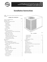
Balance PointWorksheet
70
60
I-
ra 50
0"3
_m 40
=o_
tom
3o
_c
t15:=
it= 30
"fis
===
20
10
Based on Indoor Entering Air of 70 F and Rated CFM
-10 10 17 20 30 40
OutdoorAJrTemp (Deg F)
47 50 6O
C00094
Fig. 25_50JS Balance Point Worksheet
black must be connected to the jumper wire. Insulate removed lead
end to avoid contact with chassis parts. To select high speed on
460-v GE motors, separate the black female quick connect (QC)
from the jumper lead male quick connect (QC) and connect the
black lead to the BR. Insulate the jumper to avoid contact with any
chassisparts.
Ffq l','L_l _!,'II_[d
MAINTENANCE
To ensure continuing high performance, and to minimize the
possibility of premature equipment failure, periodic maintenance
must be performed on this equipment. This heat pump unit should
be inspected at least once each year by a qualified service person.
To troubleshoot unit, refer to Table 1l.
NOTE TO EQUIPMENT OWNER: Consult your local dealer
about the availability of a maintenance contract.
The ability to properly perform maintenance on this equip-
ment requires certain expertise, mechanical skills, tools and
equipment. If you do not possess these, do not attempt to
perform any maintenance on this equipment, other than those
procedures recommended in the User's Manual. FAILURE
TO HEED THIS WARNING COULD RESULT IN SERI-
OUS INJURY OR DEATH AND POSSIBLE DAMAGE TO
THIS EQUIPMENT.
Failure to follow these warnings could result in serious injury
or death:
1. Turn off electrical power to the unit and install lockout tag
before performing any maintenance or service on this unit.
2. Use extreme caution when removing panels and parts. As
with any mechanical equipment, personal injury can result
from sharp edges.
3. Never place anything combustible either on, or in contact
with, the unit.
ing when servicing.
The minimum maintenance requirements for this equipment are as
follows:
1. Inspect air filter(s) each month. Clean or replace when
necessary.
2. Inspect indoor coil, drain pan, and condensate drain each
cooling season for cleanliness. Clean when necessary.
3. Inspect blower motor and wheel for cleanliness each cooling
season. Clean when necessary.
4. Check electrical connections for tightness and controls for
proper operation each cooling season. Service when neces-
sary.
5. Ensure wires are not contacting refrigerant tubing or sharp
sheet metal edges.
20
/