The Leader M Audio Engineering
KAV-300r
Stereo Receiver
with Theater Throughput
Instructions for Use
Owner’s Reference

KAV-300r
Stereo Receiver
with Theater Throughput
v 00.1
Krell Industries, Inc.
45 Connair Road
Orange, CT 06477-3650 USA
TEL 203-799-9954
FAX 203-891-2028
E-MAIL krell@ krellonline.com
WEBSITE http://www.krellonline.com
This product complies with the EMC directive (89/336/EEC) and the low-voltage directive (73/23/EEC).
WARNINGS
The KAV-3OOr must be placed on a firm, level surface where it is not exposed to dripping
or splashing.
The ventilation grids on the top of the KA V-3OOr must be unobstructed at all times during operation. Do not
place flammable material on top of or beneath the component.
Do not remove or bypass the ground pih on the end of the AC power cord. This can cause radio frequency
interference (RFI) to be introduced into your playback system. Operate the KAV-3OOr only with the power
cord supplied.
Turn off all systems’ power before connecting the KAV-3OOr to any compor~ent. Make sure all cable termina-
tions are of the highest quality, free from frayed ends, short circuits, or cold solder joints.
Keep any outdoor antenna away from power lines.
IMPORTANT
If an outdoor antenna is connected to the receiver, be sure the antenna system is grounded to provide protection
against voltage surges or build-up of static charges. Article 810 of the US National Electric Code (ANSI/NFPA 70)
provides information about the proper grounding of the lead-in wire to an antenna-discharge unit, size of ground-
ing conductors, location of antenna-discharge unit, connection to grounding electrodes, and requirements for
grounding electrodes. The antenna must be designed for the 88-108 MHz band.
THERE ARE NO USER SERVICEABLE PARTS INSIDE ANY KRELL PRODUCT.
Please contact your authorized Krell dealer, distributor, or Krell if you have any questions not addressed in
this reference manual.
This product is manufactured in the United States of Amedca Krell
®
is a registered trademark of Krell Industries. Inc.. and is restricted for use by Krell
Industries, INC., its subsidiaries, and authorized agents. Theater Throughput
TM
is a trademark of Krell Industries. nc. All other trademarks and tradenames
are registered to their respective companies.
@2000 by Krell Industries, Inc. All rights reserved P/N 303989

Contents
INTRODUCTION
DEFINITION OF TERMS
UNPACKING
PLACEMENT
AC Power Guidelines
FRONT PANEL DESCRIPTION
BACK PANEL DESCRIPTION
REMOTE CONTROL DESCRIPTION
Battery Installation and Removal
CONNECTING THE KAV-300r TO YOUR SYSTEM
How to Install Antennae
RECEIVER OPERATION
Power On
Tuner Functions
TAPE INPUT AND OUTPUT
OPTIONAL CONFIGURATIONS
Configuring the KAV-300r for Theater Throughput
Preamplifier Output
Adjusting Contrast and Brightness of the Tuner Display
HOW TO TROUBLESHOOT SYSTEM NOISE
QUESTIONS AND ANSWERS
WARRANTY
RETURN AUTHORIZATION PROCEDURE
SPECIFICATIONS
Page
1
.1
2
3
3
5
8
11
11
13
13
16
16
16
17
18
18
18
18
19
19
20
21
Back Cover
Krell KAV-300r
iii

Illustrations
FIGURE 1 The KAV-300r Front Panel
FIGURE 2 The KAV-300r Back Panel
FIGURE 3 The KAV-300r Remote Control
FIGURE 4 Installing the FM Antenna
Page
4
7
10
14
iv Krell KAV-300r

Introduction Definition of Terms
Thank you for your purchase of the Krell
KAV-300r Stereo Receiver with Theater
Throughput. The KAV-300r gives the audio-
phile an exceptional-sounding, two-channel
music system in a convenient package that can
stand alone or easily be integrated into a multi-
component system. The tuner combines strong
reception and quality sound with transparent
functioning and can be operated through the
front panel or the remote. Six programmable
tuner presets allow instant selection of your
favorite AM or FM stations. The FM mute and
high frequency blend features also let you con-
trol background and between-station noise
when selecting FM stations with weaker broad-
cast signals.
The Theater Throughput feature simplifies the
integration of an audio/video surround sound
processor into your system. The remote pro-
vides convenient operation of-the KAV-300r
and other Krell KAV components.
This owner’s reference manual contains impor-
tant information on placement, installation, and
operation of the KAV-300r. Please read this
information carefully. A thorough understanding
of these details will help ensure satisfactory
operation and long life for your KAV-300r and
related system components.
Following are the definitions of key terms used
in your owner’s reference manual.
CONFIGURATIONS
Theater Throughput
Theater Throughput is a Krell configuration option
that allows the signal from a surround preamp/pro-
cessor to pass through a Krell preamplifier or inte-
grated amplifier with no gain, for integrated vol-
ume and balance management of Krell home
theater systems.
INPUT AND OUTPUT CONNECTIONS
Balanced
A symmetrical input or output circuit that has
equal impedance from both input terminals to a
common ground reference point. The industry
standard for professional and sound recording
installations, balanced connections have 6 dB
more gain than single-ended connections and
allow the use of long interconnect cables.
Balanced co0nections are completely immuneto
induced noise from the system or the environ-
ment.
Single-ended
A two-wire input or output circuit. Use care when
using single-ended connections as the ground
connection is made last and broken first. Turn the
system off prior to making or breaking single-
ended connections. Single-ended connections
are not recommended for connections requiring
long cable runs.
Krell KAV-300r 1

Definition of Terms, continued Unpacking
OPERATION
Off
When the power button on the front panel
or the power key on the remote control is
pressed and the blue power LED turns off,
the component is off.
Operational Mode
When the power button on the front panel
or the power key on the remote control is
pressed and the blue power LED illumi-
nates, the component is in the operational
mode and ready to play music.
Stand-by Mode
A low power consumption status that keeps
the audio and regulator circuits at idle. Krell
recommends leaving the component in the
stand-by mode when it is not playing music.
1. Open the box and remove the top layer of
foam. You see these items:
1 KAV-300r Stereo Receiver
1 KAV-300r remote control
1 AC power cord
1 12 VDC (12 V trigger) cable
1 AM loop antenna and base
(base not attached)
1 FM indoor dipole antenna
1 matching transformer
for the FM antenna
2 AAA-size 1.5 V batteries
1 trimmer adjustment tool
1 owner’s reference manual and
warranty registration card
2. Carefully remove the unit and accessories
from the box. .
3.
Remove the foam end caps and protective
plastic wrap from the unit.
Notes
If any of the items listed above are not included,
please contact your authorized Krell dealer,
distributor, or Krell immedi-ately for assistance.
Save all packing materials. If you need to ship
your KAV-3OOr in the future, repack the unit in
its original packaging to prevent transit dam-
age.
2 Krell KAV-300r ’

Placement
Before you integrate the KAV-300r into your
system, review the following to properly place
your component. This will facilitate a clean,
trouble-free installation.
For installations inside cabinetry, extra ventila-
tion may be necessary. The KAV-300r requires
at least two inches (5 cm) of clearance on each
side and at least two inches (5 cm) of clearance
above to provide adequate ventilation. The
KAV-300r does not require a special rack or
cabinet for installation. For the dimensions of
the KAV-300r, see Specifications, on the back
cover.
The KAV-300r is not particularly hum-sensitive.
Other components may be placed on or around
the KAV-300r, as long as the ventilation grids
remain unobstructed.
Note
Some televisions and fluorescer~t lights generate
high levels of AM radiation, which can interfere
with AM reception. Electro-magnetic radiation
from some radio receiving and transmitting
equipment (such as televisions, video recorders,
digital equipment, and computers) can also
cause noise and interference.
Place the KAV-300r as close to the speakers as
possible. Run long balanced interconnect cables
to the receiver and keep speaker cable lengths to
a minimum. Speaker cable adds impedance to
the load the amplifier must drive, regardless of the
cable gauge.
AC POWER GUIDELINES
The KAV-300r has superb regulation and does
not require a dedicated AC circuit. Avoid con-
nections through extension cords or multiple AC
adapters. High quality 15 amp grounded AC
strips are acceptable. High quality AC line con-
ditioners or filters may be used if they are
grounded and meet or exceed the component’s
power supply rating of 400 VA.
Power Cord
The KAV-300r should be operated only with the
power cord supplied. Please contact your
authorized Krell dealer, distributor, or Krell
before using any devices designed to alter or
stabilize the AC power for the KAV-300r.
Krell KAV-300r
3

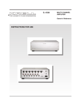
FIGURE 1 THE KAV-300r FRONT PANEL
1 2 4
6 7 8
9 12 13 14 15 16 17
3 11) 11 18
Power Functions
1 Stand-by LED
2 Power LED
3 Power Button
Tuner Functions
4 Preset Buttons
5 Tuner Display
6 Infrared Sensor
7 Mono/St Button
8 AM/FM Button
9 Tuner Button and LED
10 Tune Buttons
11 Seek Buttons
Tape Input and
Output Functions
12 Tape Button and LED
Analog Inputs
13 B-l, S-1, S-2, and
S-3 Buttons and LEDs
Processing Indicators
14 Theater LED
15 Balance LED
16 Mute LED
17 Level LEDs
Level Adjustments
18 Down/Up Buttons

Front Panel Description
See Figure 1 on page 4
The KAV-300r front panel provides on/off, tuner
selection, input selection, and volume control.
Additional functions are accessed using the
remote control. See Remote Control Descrip-
tion, on page 11.
A description of front panel buttons and their
functions follows.
Power Functions
1 Stand-by LED
The red stand-by LED illuminates when the
KAV-300r is plugged into a standard AC wall
receptacle, indicating that the receiver is ready
to be switched on.
2 Power LED
The blue power LEE) illuminates when the
KAV-300r is on.
3 Power Button
Use this button to turn the KAV-300r on and off
and also to switch the 12 VDC-(12 V trigger)
output on and off.
Tuner Functions
4 Preset Buttons
The KAV-300r has six presets that can be used
to save six AM and six FM station settings and
recall programmed settings. The station fre-
quency and assigned preset number appear in
the tuner display. Presets are programmed
through the front panel or remote control. See
Programming Presets, on page 17.
5 Tuner Display
The tuner display shows the current station
position as well as the status of other tuner
functions.
6 Infrared Sensor
The infrared sensor receives commands from
the KAV-300r remote control. For proper remote
control operation, make sure the infrared sensor
is clear of any obstructions.
7 Mono/St Button
Use this button to select mono mode (if, for
example, the broadcast signal is weak or noisy).
The tuner display window indicates MONO. A
stereo broadcast automatically decodes in
stereo as long as the signal is above the stereo
switching threshold. Mono/Stereo switching in
FM is automatic unless mono is selected.
8 AM/FM Button
Use this button to choose either AM or FM sta-
tion frequency.
9 Tuner Button and LED
Use this button to activate the tuner. The red
tuner LED above the button illuminates when
the tuner is activated. The tuner button is also
used to program presets. See Programming
Presets, on ’page 17.
10 Tune Buttons
Use these buttons to move the tuner selection
up or down in one-step increments.
11 Seek Buttons
Use these buttons to find the next available AM
or FM station frequency.
Tape Input and Output Functions
12 Tape Button and LED
Use this button to select the tape input and out-
put feature. For more information, see Tape
Input and Output, on page 17. The red tape
LED.. located above the tape button, illuminates
when the tape feature ~s activated.
Krell KAV-300r 5

Front Panel, continued
See Figure 1 on page 4
Analog Inputs
13 B-l, S-1, S-2, and S-3
Buttons and LEDs
Use these buttons to choose from one balanced
XLR source (B-l), and three single-ended RCA
sources (S-1, S-2, and S-3).The red LED above
the selected input illuminates.
Processing Indicators
14 Theater LED
The red Theater Throughput LED illuminates
when you select any of the inputs (S-1, So2, S-3,
or B-l) as a Theater Throughput source. See
Optional Configurations, on page 18.
15 Balance LED
The red balance LEDs illuminate when you
adjust the balance to the left or right channel.
Balance adjustment is activated only through
the remote control. See Balance Keys (47), on
page 12.
16 Mute LED
The red mute LED illuminates when you press
the mute key on the remote control. Mute inter-
rupts the signal of the input you have selected.
To unmute, press mute again.
17 Level LEDs
The red volume level LEDs illuminate to show
the system output level.
Level Adjustments
18 Down/Up Buttons
Use these buttons to adjust the system output
level (left button decreases volume; right button
increases volume) and system balance levels.
Krell KAV-300r

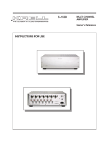
FIGURE 2 THE KAV- 300r BACK PANEL
19 2¸0 21 23 24 25 26 27 22
28 28 29 30
Antenna
Connections
19 AM Ant
20 FM Ant
Amplifier Channels
21 Right Outp.ut
22 Left Output
, Remote Controls
23 12 VDC Out
24 RC-5
Analog Inputs
and Outputs
25 Preamp Out
26 Tape Out/In
27 S-3, S-2, S-1, B-1 Inputs
Fuses
28 Fuse AGC 12
29 Line Fuse
Power
30 IEC Power Receptacle

Back Panel Description
See Figure 2 on page 7
The back panel provides connections for AM
and FM antennae, inputs and outputs, and
power. A description of back panel components
and their functions follows.
Antenna Connections
19 AM Ant
The KAV-300r is equipped with one AM loop
antenna, which must be attached to the AM
antenna screw terminal. See How to Install
Antennae, on page 13.
20 FM Ant
The KAV-300r is equipped with one FM dipole
antenna, which must be plugged in to the
FM antenna coaxial connector. See Figure 4,
Installing the FMAntenna, on page 14, and
How to Install Antennae, on page 13.
Amplifier Channels
21 Right Output
22 Left Output
The KAv-300r is equipped with standard binding
posts for each amplifier channel. These connec-
tors accept bare wire, banana plugs, pins, or
spade lugs. Use the red terminal for the positive
connection and the black terminal for the negative
connection.
Remote Controls
23 12 VDC Out
The 12 VDC (.12 V trigger) output allows the
KAV-300r to activate other Krell components
and other devices that have a 12 Volt trigger
input.
Notes
The 12 VDC output power is limited to 30 ma.
Refer to the owner’s manual of every com-
ponent used h~ a custom installation to take full
advantage of the KA V-3OOr remote capability.
24 RC-5
The RC-5 input accepts baseband RC-5 input
commands from hardwired remote controllers.
Analog Inputs and Outputs
25 Preamp Out
The KAV-300r is equipped with a pair of single-
ended preamplifier outputs.
Note
The amplifier channel outputs are always
active, even when the KAV-3OOr is only being
used as a preamplifier.
26 Tape Out/In
The KAV-300r is equipped with one set of sin-
gle-ended tape inputs and outputs via RCA con-
nectors.
27 S-3, S-2, S-1, B-1 Inputs
The KAV-300r is equipped with three sets (left
and right) of single-ended inputs via RCA con-
nectors. The ’KAV-300r is also equipped with
one set (left and right) of balanced inputs via
XLR connectors.
Fuses
28 Fuse AGC 12
The AGC 12 fuses protect the KAV-300r
against short circuits in speaker output.
29 Line Fuse
The 50/60 Hz line fuse protects the KAV-300r
against short circuits from the AC power lines.
Krell KAV-300r "

Back Panel Description,
See Figure 2 on page 7
con~nued
Note
Fuses must be replaced with the fuse value
specified on the KAV-3OOr back pane/.
Power
30 IEC Power Receptacle
The KAV-300r is equipped with an IEC power
receptacle for use with the AC power cord.
Krell KAV-3OOr

FIGURE 3 THE KAV-300r REM()TE CONTROL
31
34
35
36
37
38
41
42
32
33
39
40
44
43
45
46
Power Functions
3t Pwr Key
32 Amp/Pre Key
Tape Input and Output
33 Tape Key
Tuner Functions
34 FM Mute Key
35 Mon/St Key
36 Analog Input Keys
37 Tuner Key
38 AM/FM Key
39 Tune Keys
40 Seek Keys
41 Prog/Scan Key
Advanced Functions
42 A/B/Mem Key
43 Rep/Store Key
44 Rnd/HFB Key
45 Mute Key
46 Volume Keys
47 Balance Keys
Note: Some keys on the remote control" do not function with the KAV-3OOr,
10 Krell KAV-300r

Remote Control Description
See Figure 3 on page 10
The KAV-300r remote control provides power
on/off, and basic and advanced tuner functions.
BATTERY INSTALLATION
AND REMOVAL
The KAV-300r handheld remote control uses
two AAA-size 1.5 Volt batteries. Batteries are
included with the shipment.
To install the batteries in the handheld remote
control:
1. Remove the backplate by sliding the cover
down.
2.
Install the batteries, following the battery posi-
tion diagram on the plastic battery receptacle.
3. Replace the backplate.
The remote control is ready for operation.
Replace batteries when remote-control function
becomes intermittent. Remove batteries if the
remote control is not to be used for a long period
of time. Battery leakage can damage the remote
control.
A description of the remote control keys and
their functions follows.
Notes
When a remote control function key is pressed,
the KAV-3OOr blue power LED flashes. When
the key is released, the flashing stops.
The CD function keys (CD, track, pause, play,
open, stop), and D/A, Dig In, Gain, Phase, and
Intro keys are not functional for the KAV-3OOr.
Power Functions
31 Pwr Key
Use this key to turn the KAV-300r on and off.
32 Amp/Pre Key
Use this key to activate the KAV-300r remote
control and access receiver commands.
Tape Input and Output
33 Tape Key
Use this key to compare the output signal of a
three-head analog tape recorder to the output
signal of an audio source, when making a
recording. The red tape LED illuminates when
the tape recorder is activated. The red tape
LED does not illuminate when the audio source
is activated. See Tape Input and Output, on
page 17.
Tuner Functions
The keypad keys access FM mute and
mono/stereo functions, analog input sources, and
tuner functions. A description of these keys and
their functions follows.
Note
Keypad numbers 1-6 are active only for pro-
gramming and accessing tuner presets. See
Programming Presets, on page 17. Keypad
numbers 7-9, O, and +10 are not functional on
the KAV-’3OOr.
34 FM Mute Key
Use this key to turn FM mute on and off. FM
mute off allows you to hear FM stations with
broadcast signals not strong enough for clear
reception. To turn mute on, press the FM mute
key. Mute on reduces the noise between station
positions, for better monitoring of audio output
as you tune.
Note
The tuner display indicates mute on; it does not
indicate mute off.
Krell KAV-300r
11

Remote Control Description, continued
See Figure 3 on page 10
35 MoniSt Key
Use this key to select mono mode (if, for exam-
ple, the signal is weak and noisy). The tuner
display indicates MONO. A stereo broadcast is
automatically decoded in stereo as long as the
signal is above the stereo switching threshold.
Mono/stereo switching in FM is automatic
unless mono is selected.
36 Analog Input Keys
Use these keys to choose from one balanced
XLR source (B-l) and three single-ended RCA
sources (S-1, S-2, and S-3).
Note
B-2 and S-4 analog inputs are not func-
tional on the KAV-3OOr.
37 Tuner Key
Use this key to select the tuner,
38 AM/FM Key
Use this key to select either AM or FM station
frequency.
39 Tune Keys
Use these keys to move the tuner selec-
tion up or down in one-step increments,
40 Seek Keys
Use these keys to find the next available AM or
FM station frequency.
41 Prog/Scan Key
Use this key to move the tuner selection to the
next available AM or FM station frequency. The
tuner pauses for five seconds, then moves to the
next available station .’To stop the tuner from mov-
ing to the next station, press the scan key again.
Advanced Functions
43 Rep/Store Key
Use this key to store a preset selection. See
Programming Presets, on page 17.
44 Rnd/HFB Key
Use this key to reduce noise when an FM station
with weak broadcast signal and high background
noise is selected. Note that some high frequency
stereo separation is reduced along with the back-
ground noise.
45 Mute Key
Use this key to interrupt the signal of the select-
ed input. The red mute LED (16) on the front
panel illuminates when you press the mute key.
46 Volume Keys
Use these keys to adjust the volume of the
KAV-300r output (left key decreases volume;
right key increases volume). The level LEDs on
the front panel indicate the volume level.
47 Balance Keys
Use these keys to shift balance to the left or
right in 1 dB increments. The "L" position mutes
the right channel. The "R" position mutes the left
channel.
When either balance key is pressed, the bal-
ance LED (1.5) illuminates and the volume level
LEDs (17) convert to balance indicators. The
center LED remains illuminated, indicating the
center balance position. As balance is adjusted
left or right, a second LED illuminates, indicat-
ing. the modified balance setting.
If the balance has been set off-center, the balance
LED remains illuminated after the adjustment.
After five seconds of inactivity or a volume adjust-
ment, the level LEDs revert to volume indicators.
42 NB/Mem Key
Use this key to access programmed presets. See
Programming Presets, on page 17.
12 Krell KAV-300r

Connecting the KAV-300r
to Your System
To prevent the introduction of hum or other
noise into the system, organize all wiring neatly
between the KAV-300r and other system com-
ponents and separate AC wires from audio
cables.
The KAV-300r uses standard binding posts for
each amplifier, channel. These connectors
accept bare wire, banana plugs, pins, or spade
lugs. Use the red terminal for the positive con-
nection and the black terminal for the negative
connection.
Connect the speaker cables to the left (22)
and right (21) amplifier channel output ter-
minals located on the back panel.
Connect the left and right outputs of your
source components to the analog inputs
(27) on the KAV-300r.
Plug the AC power cord into the IEC power
receptacle (30) on the KAV-300r back panel.
Plug the remaining end into the AC wall
receptacle. The red stand-by LED (1) on the
front panel illuminates.
The KAV-300r is equipped with one set of bal-
anced inputs (B-l) via XLR connectors, three sets
of single-ended inputs (S-1, S-2, and S-3) via
RCA connectors, and one tape input and output
loop via RCA connectors. Any balanced or single-
ended input may be configured for Theater
Throughput. See Optional Configurations, on
page 18.
Krell recommends using balanced interconnect
cables. Balanced interconnect cables can mini-
mize sonic loss and are immune to induced
noise, especially for installations using long
cables. The balanced connection has 6 dB more
gain than single-ended connections. When level
matching is critical, please keep this specification
in mind.
Notes
All inputs and outputs are labeled on the back
panel Maintain the correct left~right orientation.
Single-ended preamplifier outputs can be used
to simultaneously feed different systems.
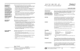
HOW TO INSTALL ANTENNAE
FM Indoor Dipole Antenna
See Figure 4 on page 14
An FM indoor dipole antenna and matching
transformer are included with the KAV-300r.
To connect the FM indoor dipole antenna:
1. Loosen the two screws on the matching trans-
former (c).
2.
Insert the antenna spade lugs (b) between the
screw heads and the screw.bases (c).
3. Tighten screws to secure the spade lugs.
4.
Plug the transformer’s coaxial connector (d)
into the F.M Ant coaxial connector (f) on the
back panel.
5. Stretch out the antenna wires and move the
antenna around to find the best signal
strength and .clarity.
6. Attach the antenna to the wall or other pre-
ferred location, such as inside cabinetry.
Small nails can be driven through the holes
in the plastic caps, located at the end of the
antenna wires, to secure the antenna.
Krell KAV-300r 13

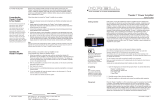
FIGURE 4 INSTALLING THE FM ANTENNA
d
ANT
AM ANT
KRELL INDUSTRIES, INC.
45 CONNAIR RD.
ORANGE, CT 06477-3650
USA
1 FM Indoor Dipole Antenna
2 Matching Transformer
3 Back Panel, KAV-300r
a End Cap
b Spade Lugs
c Screws
d Transformer Coaxial Connector
e AM Antenna Screw Terminal
f FM Antenna Coaxial Connector
14 Krell KAV-300r

Connecting the KAV-300r
to your System, continued
HOW TO INSTALL ANTENNAE,
continued
Notes
For optimum tuner reception and performance,
use an outdoor FM antenna. The antenna
needs to have good gain and directional char-
acteristics, be mounted as high as possible
away from any large metal objects, and point
toward the transmitter.
When the outdoor antenna is installed, discon-
nect the FM indoor antenna.
AM Loop Antenna
An AM loop antenna is included with the
KAV-300r.
Note
The AM loop antenna must be connected even
when an outdoor antenna is installed because
the AM loop antenna forms part of the AM tun-
ing circuit.
To connect the AM loop antenna:
1. Loosen screws on the AM Antenna screw
terminal (19) on the back panel.
2. Insert spade lugs between screw heads and
screw bases.
3. Tighten screws to secure spade lugs.
4. Move the AM loop antenna around to find
the best signal strength and clarity.
5. Use the antenna base provided to attach the
AM loop antenna to a wall or other location, if
desired. T, he base can be taped to a surface or
screwed in (screw not provided).
For enhanced AM reception, you can connect a
single connector wire (approximately 20 f~eet)
the pole marked AM ANT(19) on the back panel
of the KAV-300r. Extend the wire to find the
best signal strength and clarity.
Kretl KAV-300r 15

Receiver Operation
The KAV-300r provides input and preset selec-
tion and volume control from the front panel.
The remote control provides additional func-
tions. Instructions for receiver operation follow.
POWER ON
1. Turn the receiver on by pressing the power
button (3) on the front panel or pressing the
pwr key (31) on the remote control.
The KAV-300r power supply incorporates a
slow start protection circuit that prevents
excessive current from reaching the audio
circuitry upon initial power on. After pressing
the power button (3) or pwr key (31), the
stand-by LED (1) on the front panel extin-
guishes, and the blue power LED (2) and
the tuner display (5) illuminate. There is
short delay, followed by an audible click.
This click is the protection oircuitry disen-
gaging. The KAV-300r is now ready for
operation.
2. Select a source device either from the front
panel (13) or using the remote control (36).
The source begins to play.
3. Set the volume to a comfortable listening
level.
4. When changing sources, lower the volume to
off (18), or mute the output (45). Mute
Key, on page 12. This ensures that the next
source played does not damage your system
with a high outputtransient.
TUNER FUNCTIONS
Selecting a Station
1.
Press the AM/FM button (8) on the front
panel or the AM/FM key (38) on the remote
control to select the desired mode.
2. Select the desired station frequency. There
are three ways to select a station:
TunemUse these buttons (10) or keys (39)
to move the tuner selection up or down in
one-step increments.
Seek--Use these buttons (11) or keys (40)
find the next available AM or FM station
frequency.
Prog/ScanmUse this key (41) to move the
tuner selection to the next available AM or
FM frequency. The tuner pauses for five
seconds, then moves to the next available
station. To stop the tuner from moving to the
next station, press the scan key again.
The selected station frequency appears in the
tuner display (5) on the front panel.
16 Krell KAV-300r
Page is loading ...
Page is loading ...
Page is loading ...
Page is loading ...
Page is loading ...
/