Page is loading ...

SERVICE MANUAL
CM 25
Unit Serial Number Range: 1009XXXXC25 to Present
(From October 2009 to Present)
DocID: 00G00045EA

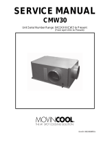
SERIAL NUMBER LOCATION AND IDENTIFICATION
Nameplate Label Position
Nameplate Label
COOLING AMPS. WITH PUMP
COMPR. OUTPUT
REFRIGERANT/TOTAL CHARGE
DESIGN PRESSURE LO/HI
PART NO./WEIGHT
SERIAL NO.
Month
Model
Sequential
Number
Year
▲▲ XXXX ###
© 2012 DENSO SALES CALIFORNIA, INC.
All rights reserved. This book may not be reproduced or copied, in
whole or in part, without the written permission of the publisher. DENSO
SALES CALIFORNIA, INC. reserves the right to make changes without
prior notice. MovinCool
®, Office Pro® and SpotCool® are registered
trademarks of DENSO Corporation.

Table of Contents
Operation Section
1. PRECAUTIONS FOR SAFETY
1.1 Foreword. . . . . . . . . . . . . . . . . . . . . . . . . . . . . . . . . . . . . . . . . . . . . . . . . . . . . . . . . . . . . . . . . . . . . . . 6
1.2 Definition of Terms . . . . . . . . . . . . . . . . . . . . . . . . . . . . . . . . . . . . . . . . . . . . . . . . . . . . . . . . . . . . . . . 6
1.3 General Precautions. . . . . . . . . . . . . . . . . . . . . . . . . . . . . . . . . . . . . . . . . . . . . . . . . . . . . . . . . . . . . . 6
2. SPECIFICATIONS
2.1 Exterior Dimension Diagram. . . . . . . . . . . . . . . . . . . . . . . . . . . . . . . . . . . . . . . . . . . . . . . . . . . . . . . . 7
2.2 Technical Specifications . . . . . . . . . . . . . . . . . . . . . . . . . . . . . . . . . . . . . . . . . . . . . . . . . . . . . . . . . . . 8
2.3 Characteristics . . . . . . . . . . . . . . . . . . . . . . . . . . . . . . . . . . . . . . . . . . . . . . . . . . . . . . . . . . . . . . . . . 10
3. CONSTRUCTION
3.1 Exterior Components . . . . . . . . . . . . . . . . . . . . . . . . . . . . . . . . . . . . . . . . . . . . . . . . . . . . . . . . . . . . 15
3.2 Internal Structure . . . . . . . . . . . . . . . . . . . . . . . . . . . . . . . . . . . . . . . . . . . . . . . . . . . . . . . . . . . . . . . 16
3.3 Basic Construction . . . . . . . . . . . . . . . . . . . . . . . . . . . . . . . . . . . . . . . . . . . . . . . . . . . . . . . . . . . . . . 18
3.4 Air Flow. . . . . . . . . . . . . . . . . . . . . . . . . . . . . . . . . . . . . . . . . . . . . . . . . . . . . . . . . . . . . . . . . . . . . . . 18
4. REFRIGERATION SYSTEM
4.1 Refrigeration System Construction. . . . . . . . . . . . . . . . . . . . . . . . . . . . . . . . . . . . . . . . . . . . . . . . . . 19
4.2 Compressor . . . . . . . . . . . . . . . . . . . . . . . . . . . . . . . . . . . . . . . . . . . . . . . . . . . . . . . . . . . . . . . . . . . 20
4.3 Condenser . . . . . . . . . . . . . . . . . . . . . . . . . . . . . . . . . . . . . . . . . . . . . . . . . . . . . . . . . . . . . . . . . . . . 22
4.4 Electronic Expansion Valve . . . . . . . . . . . . . . . . . . . . . . . . . . . . . . . . . . . . . . . . . . . . . . . . . . . . . . . 23
4.5 Evaporator . . . . . . . . . . . . . . . . . . . . . . . . . . . . . . . . . . . . . . . . . . . . . . . . . . . . . . . . . . . . . . . . . . . . 23
4.6 Accumulator . . . . . . . . . . . . . . . . . . . . . . . . . . . . . . . . . . . . . . . . . . . . . . . . . . . . . . . . . . . . . . . . . . . 24
4.7 High-Pressure Switch. . . . . . . . . . . . . . . . . . . . . . . . . . . . . . . . . . . . . . . . . . . . . . . . . . . . . . . . . . . . 24
5. ELECTRICAL SYSTEM
5.1 Circuit Diagram. . . . . . . . . . . . . . . . . . . . . . . . . . . . . . . . . . . . . . . . . . . . . . . . . . . . . . . . . . . . . . . . . 25
5.2 Control Box. . . . . . . . . . . . . . . . . . . . . . . . . . . . . . . . . . . . . . . . . . . . . . . . . . . . . . . . . . . . . . . . . . . . 26
5.3 Power Supply Requirements . . . . . . . . . . . . . . . . . . . . . . . . . . . . . . . . . . . . . . . . . . . . . . . . . . . . . . 27
5.4 Wall Mounted Controller (WMC). . . . . . . . . . . . . . . . . . . . . . . . . . . . . . . . . . . . . . . . . . . . . . . . . . . . 28
5.5 Field-Supplied Millivolt Wall Thermostat (MWT) Connection . . . . . . . . . . . . . . . . . . . . . . . . . . . . . . 32
5.6 Warning Signal Connection (Output Signal Terminal L+ and L-) . . . . . . . . . . . . . . . . . . . . . . . . . . . 33
5.7 Fire Alarm Control Panel Connection (Input Signal Terminal E+ and E-). . . . . . . . . . . . . . . . . . . . . 34
5.8 Basic Operation . . . . . . . . . . . . . . . . . . . . . . . . . . . . . . . . . . . . . . . . . . . . . . . . . . . . . . . . . . . . . . . . 35
5.9 Compressor Operation . . . . . . . . . . . . . . . . . . . . . . . . . . . . . . . . . . . . . . . . . . . . . . . . . . . . . . . . . . . 35
5.10 Electronic Expansion Valve Operation . . . . . . . . . . . . . . . . . . . . . . . . . . . . . . . . . . . . . . . . . . . . . . . 35
5.11 Evaporator Fan Motor Operation . . . . . . . . . . . . . . . . . . . . . . . . . . . . . . . . . . . . . . . . . . . . . . . . . . . 36
Table of Contents

Table of Contents
5.12 Condenser Fan Motor Operation . . . . . . . . . . . . . . . . . . . . . . . . . . . . . . . . . . . . . . . . . . . . . . . . . . . 36
5.13 Internal Drain Pump Operation. . . . . . . . . . . . . . . . . . . . . . . . . . . . . . . . . . . . . . . . . . . . . . . . . . . . . 37
5.14 Anti-Frost Control . . . . . . . . . . . . . . . . . . . . . . . . . . . . . . . . . . . . . . . . . . . . . . . . . . . . . . . . . . . . . . . 37
5.15 Fan Motor Reverse Rotation Protection . . . . . . . . . . . . . . . . . . . . . . . . . . . . . . . . . . . . . . . . . . . . . . 37
5.16 Automatic Restart After Power Interruption (Automatic Recovery Function) . . . . . . . . . . . . . . . . . . 37
5.17 Relay Board . . . . . . . . . . . . . . . . . . . . . . . . . . . . . . . . . . . . . . . . . . . . . . . . . . . . . . . . . . . . . . . . . . . 38
5.18 Compressor . . . . . . . . . . . . . . . . . . . . . . . . . . . . . . . . . . . . . . . . . . . . . . . . . . . . . . . . . . . . . . . . . . . 40
5.19 Fan Motor . . . . . . . . . . . . . . . . . . . . . . . . . . . . . . . . . . . . . . . . . . . . . . . . . . . . . . . . . . . . . . . . . . . . . 41
5.20 Temperature Thermistor . . . . . . . . . . . . . . . . . . . . . . . . . . . . . . . . . . . . . . . . . . . . . . . . . . . . . . . . . . 42
5.21 Float Switch . . . . . . . . . . . . . . . . . . . . . . . . . . . . . . . . . . . . . . . . . . . . . . . . . . . . . . . . . . . . . . . . . . . 42

Table of Contents
Repair Section
6. TROUBLESHOOTING
6.1 Troubleshooting . . . . . . . . . . . . . . . . . . . . . . . . . . . . . . . . . . . . . . . . . . . . . . . . . . . . . . . . . . . . . . . . 43
6.2 Self-Diagnostic Codes . . . . . . . . . . . . . . . . . . . . . . . . . . . . . . . . . . . . . . . . . . . . . . . . . . . . . . . . . . . 44
6.3 Troubleshooting Chart . . . . . . . . . . . . . . . . . . . . . . . . . . . . . . . . . . . . . . . . . . . . . . . . . . . . . . . . . . . 50
6.4 Self-Diagnostic Code Display Operation and Control. . . . . . . . . . . . . . . . . . . . . . . . . . . . . . . . . . . . 56
6.5 Self-Diagnostic Code Records Display Operation (Only When Connected With WMC) . . . . . . . . . 57
6.6 Operational Status Display Control (Only When Connected With WMC). . . . . . . . . . . . . . . . . . . . . 59
6.7 Initialize Fan Motor . . . . . . . . . . . . . . . . . . . . . . . . . . . . . . . . . . . . . . . . . . . . . . . . . . . . . . . . . . . . . . 61
6.8 TEST Mode. . . . . . . . . . . . . . . . . . . . . . . . . . . . . . . . . . . . . . . . . . . . . . . . . . . . . . . . . . . . . . . . . . . . 63
6.9 Basic Inspection . . . . . . . . . . . . . . . . . . . . . . . . . . . . . . . . . . . . . . . . . . . . . . . . . . . . . . . . . . . . . . . . 64
6.10 Inspection of Compressor. . . . . . . . . . . . . . . . . . . . . . . . . . . . . . . . . . . . . . . . . . . . . . . . . . . . . . . . . 65
6.11 Inspection of Electronic Expansion Valve Control Coil . . . . . . . . . . . . . . . . . . . . . . . . . . . . . . . . . . . 66
6.12 Inspection of Thermistor. . . . . . . . . . . . . . . . . . . . . . . . . . . . . . . . . . . . . . . . . . . . . . . . . . . . . . . . . . 66
6.13 Inspection of Wiring Connection. . . . . . . . . . . . . . . . . . . . . . . . . . . . . . . . . . . . . . . . . . . . . . . . . . . . 66
6.14 Inspection of Refrigeration System. . . . . . . . . . . . . . . . . . . . . . . . . . . . . . . . . . . . . . . . . . . . . . . . . . 67
7. DISASSEMBLY
7.1 Parts Construction . . . . . . . . . . . . . . . . . . . . . . . . . . . . . . . . . . . . . . . . . . . . . . . . . . . . . . . . . . . . . . 68
7.2 Disassembly . . . . . . . . . . . . . . . . . . . . . . . . . . . . . . . . . . . . . . . . . . . . . . . . . . . . . . . . . . . . . . . . . . . 69
7.3 Removal of Evaporator Fan Assembly. . . . . . . . . . . . . . . . . . . . . . . . . . . . . . . . . . . . . . . . . . . . . . . 71
7.4 Removal of Condenser Fan Assembly. . . . . . . . . . . . . . . . . . . . . . . . . . . . . . . . . . . . . . . . . . . . . . .73
7.5 Removal of Electrical Components. . . . . . . . . . . . . . . . . . . . . . . . . . . . . . . . . . . . . . . . . . . . . . . . . . 75
8. REFRIGERATION SYSTEM REPAIR
8.1 Repair of Refrigeration System. . . . . . . . . . . . . . . . . . . . . . . . . . . . . . . . . . . . . . . . . . . . . . . . . . . . . 78
8.2 Removal of Refrigeration System Components . . . . . . . . . . . . . . . . . . . . . . . . . . . . . . . . . . . . . . . . 80
8.3 Charging the System with R-410A Refrigerant. . . . . . . . . . . . . . . . . . . . . . . . . . . . . . . . . . . . . . . . . 81
8.4 Refrigerant Charging Work. . . . . . . . . . . . . . . . . . . . . . . . . . . . . . . . . . . . . . . . . . . . . . . . . . . . . . . . 86
9. REASSEMBLY
9.1 Reassembly of Unit. . . . . . . . . . . . . . . . . . . . . . . . . . . . . . . . . . . . . . . . . . . . . . . . . . . . . . . . . . . . . . 88
9.2 Compressor Mounting . . . . . . . . . . . . . . . . . . . . . . . . . . . . . . . . . . . . . . . . . . . . . . . . . . . . . . . . . . . 88
9.3 Evaporator Fan Assembly . . . . . . . . . . . . . . . . . . . . . . . . . . . . . . . . . . . . . . . . . . . . . . . . . . . . . . . . 88
9.4 Condenser Fan Assembly . . . . . . . . . . . . . . . . . . . . . . . . . . . . . . . . . . . . . . . . . . . . . . . . . . . . . . . . 88
9.5 Wiring Notice . . . . . . . . . . . . . . . . . . . . . . . . . . . . . . . . . . . . . . . . . . . . . . . . . . . . . . . . . . . . . . . . . . 88
9.6 Perform an Inspection. . . . . . . . . . . . . . . . . . . . . . . . . . . . . . . . . . . . . . . . . . . . . . . . . . . . . . . . . . . . 88

Operation Section
6
1. PRECAUTIONS FOR SAFETY
1.1 Foreword
• This manual has been published to service the MovinCool CM 25. Use this manual only when
servicing the CM 25.
1.2 Definition of Terms
1.3 General Precautions
WARNING
• All electrical work should only be performed by qualified electrical technician. Repair to
electrical components by non-certified technicians may result in personal injury and/or
damage to the unit. All electrical components replaced must be genuine MovinCool parts,
purchased from an authorized reseller.
• Disconnect power supply from the unit before performing any service.
• Before replacing any refrigeration components, recover the refrigerant using standard
recovery procedures and equipment.
• When handling refrigerant, always wear proper eye protection and do not allow the
refrigerant to come in contact with your skin.
• Do not expose refrigerant to an open flame.
• The power supply for this unit should be a dedicated single outlet circuit with a UL
recognized short-circuit and ground-fault protective breaker to prevent electrical shock
from the unit.
• When brazing any tubing, always wear eye protection, and work only in a well ventilated
area.
• Be careful of any sharp edges when working on this unit.
Describes precautions that should be observed in order to prevent injury to
the user during installation or unit operation.
Describes precautions that should be observed in order to prevent damage to
the unit or its components, which may occur during installation or unit
operation if sufficient care is not taken.
NOTE Provides additional information that facilitates installation or unit operation.
WARNING
CAUTION

Operation Section
7
2. SPECIFICATIONS
2.1 Exterior Dimension Diagram
ILL00663-00
53
16
29.8
DIA. 0.6
31.54
DIA. 12
DIA. 12
17.8 0.80.9
51.3
2.4
10.2
14.4
6.5
20
9.5
3.4
0.8
0.6
34.6
10.7
UNIT: inch
4 x DIA. 0.6
0.9
19.7 22.4
4
1.1
DIA. 13.8

Operation Section
8
2.2 Technical Specifications
Electronic Features
Operation
Wall Mounted Controller (WMC) with LCD
display
Control Electronic with Inverter Circuit
Electronic Characteristics
Voltage Requirement Single-Phase 208/230 V 60 Hz
Min.- Max. Voltage Min. 198 V, Max. 253 V
Recommended Fuse Size 20 A
Cooling Capacity and Power Consumption
Evaporator: 80°F (27°C), 50% RH/
Condenser: 95°F (35°C), 50% RH
Total Cooling Capacity
*1
25000/25000 Btu/h (7320/7320 W)
Sensible Cooling Capacity
*1
18000/18000 Btu/h (5280/5280 W)
Power Consumption
*1
2.90/2.90 kW
Current Consumption
*1
13.6/12.6 A
Power Factor 98/99%
Evaporator: 72°F (22°C), 50% RH/
Condenser: 95°F (35°C), 50% RH
Total Cooling Capacity
*1
25000/25000 Btu/h (7320/7320 W)
Sensible Cooling Capacity
*1
18900/18900 Btu/h (5580/5580 W)
Power Consumption
*1
3.20/3.20 kW
Current Consumption
*1
15.0/15.0 A
Power Factor 98/98%
SEER
*1
14/14
Refrigerant Circuit
Compressor
Compression
Type
Hermetic Swing Inverter
Evaporator Plate Fin
Condenser Plate Fin
Refrigerant Control Electronic Expansion Valve
Evaporator
Type of Fan Centrifugal Fan
Air Flow
High 850/950 CFM (1445/1615 m
3
/h)
Low 700/800 CFM (1190/1360 m
3
/h)
Max. External Static Pressure 0.6 IWG (150 Pa)
Motor Output 0.21 kW
Condenser
Type of Fan Centrifugal Fan
Air Flow
High 1490/1600 CFM (2530/2720 m
3
/h)
Low 1190/1300 CFM (2020/2210 m
3
/h)
Max. External Static Pressure 0.5 IWG (125 Pa)
Motor Output 0.35 kW
Refrigerant
Type R-410A
Amount 2.31 lb (1.05 kg)

Operation Section
9
• Specifications are subject to change without notice.
< NOTE >
*1 :With two 20-foot (6.1 m) ducts containing one 90° bend each, supply grill and return grill with filter {0.30 IWG (75 Pa)
external static pressure} on high fan speed.
*2 :Confirm pressure drop of duct, grills, and filter with manufactures specifications.
Signal Connection
Fire Alarm Input
• Dry contact type (recommended)
• No-voltage contact input/Contact
resistance less than 100 ohm
Warning Signal Output 2 A at 30 V DC/AC max. with resistive load
Dimension
W x D x H (without flange) 53 x 32 x 20 in (1346 x 813 x 508 mm)
W x D x H (with flange) 57 x 36 x 20 in (1448 x 914 x 508 mm)
Weight Net/Shipping 310/353 lb (140/160 kg)
Internal Drain Pump Capacity
Pump Rate 5.0 gal/h (19 L/h)
Head 4 ft (1.2 m)
Operating Condition Range
Evaporator
Max. Inlet Air 95°F (35°C), 50% RH
Min. Inlet Air 60°F (15.5°C), 50% RH
Condenser
Max. Inlet Air 113°F (45°C)
Min. Inlet Air 50°F (10°C)
Maximum Duct Length
Cold Duct
*2
120 ft (36.6 m)
Hot Duct
*2
90 ft (27.4 m)
Maximum Sound Level
Measured at 1 m under the
ceiling with evaporator duct and
ceiling tile.
55/55 dB (A)

Operation Section
10
2.3 Characteristics
• Value range for each outdoor temperature shown in the graphs is based on the compressor speed.
(1) How to read the characteristics
< NOTE >
Condenser inlet air temperatures are at 50% relative humidity.
IILL00675-00
Evaporator
Inlet Air Dry Bulb Temp. °F (°C) Cooling Capacity (x10
3
Btu/h)
Evaporator Inlet Air Wet Bulb Temp. °F (°C)
10
5
15
20
25
30
35
40
95 (35)
86 (30)
77 (25)
68 (20)
59 (15)
50
(10)
59
(15)
68
(20)
77
(25)
41
(5)
< Example >
Condition:
Evaporator Inlet Air Dry Bulb : 77 °F (25 °C)
Evaporator Inlet Air Wet Bulb : 59 °F (15 °C)
Condenser Inlet Air Temperature : 95 °F (35 °C)
Cooling Capacity:
Max: 24000 Btu/h
Min: 8000 Btu/h
Condenser Inlet Air
Temperature
115°F (46°C)
Condenser Inlet Air
Temperature
95°F (35°C)
Condenser Inlet Air
Temperature
50°F (10°C)

Operation Section
11
(2) Cooling capacity curve
< NOTE >
Condenser inlet air temperatures are at 50% relative humidity.
IILL00676-00
Evaporator
Inlet Air Dry Bulb Temp. °F (°C) Cooling Capacity (x10
3
Btu/h)
Evaporator Inlet Air Wet Bulb Temp. °F (°C)
10
5
15
20
25
30
35
40
95 (35)
86 (30)
77 (25)
68 (20)
59 (15)
50
(10)
59
(15)
68
(20)
77
(25)
41
(5)
Condenser Inlet Air
Temperature
115°F (46°C)
Condenser Inlet Air
Temperature
95°F (35°C)
Condenser Inlet Air
Temperature
50°F (10°C)

Operation Section
12
(3) Power consumption curve
< NOTE >
Condenser inlet air temperatures are at 50% relative humidity.
Evaporator
Inlet Air Dry Bulb Temp.°F (°C) Power Consumption (kW)
Evaporator Inlet Air Wet Bulb Temp.°F (°C)
95(35)
86(30)
77(25)
68(20)
59(15)
59
(15)
68
(20)
77
(25)
86
(30)
50
(10)
95
(35)
0.5
0
1.5
1.0
2.5
2.0
3.5
3.0
4.0
Condenser Inlet Air
Temperature
95°F (35°C)
Condenser Inlet Air
Temperature
50°F (10°C)
Condenser Inlet Air
Temperature
115°F (46°C)
ILL00677-00

Operation Section
13
(4) Current consumption curve
< NOTE >
Condenser inlet air temperatures are at 50% relative humidity.
Evaporator Inlet Air Wet Bulb Temp.°F (°C)
Evaporator
Inlet Air Dry Bulb Temp. °F (°C) Current Consumption (A)
59
(15)
68
(20)
77
(25)
86
(30)
50
(10)
95
(35)
95(35)
86(30)
77(25)
68(20)
59(15)
2
0
6
4
10
8
14
12
16
Condenser Inlet Air
Temperature
115°F (46°C)
Condenser Inlet Air
Temperature
95°F (35°C)
Condenser Inlet Air
Temperature
50°F (10°C)
ILL00678-00

Operation Section
14
(5) Cool air temperature difference curve
< NOTE >
Condenser inlet air temperatures are at 50% relative humidity.
Evaporator
Inlet Air Dry Bulb Temp.°F (°C)
Temperature Difference Between
Evaporator Inlet and Outlet Air (Delta-T) °F (°C)
Evaporator Inlet Air Wet Bulb Temp.°F (°C)
95(35)
86(30)
77(25)
68(20)
59(15)
50
(10)
59
(15)
68
(20)
77
(25)
41
(5)
7.2 (4)
3.6 (2)
10.8 (6)
14.4 (8)
18.0(10)
21.6(12)
25.2(14)
28.8(16)
Condenser Inlet Air
Temperature
115°F (46°C)
Condenser Inlet Air
Temperature
95°F (35°C)
Condenser Inlet Air
Temperature
50°F (10°C)
ILL00679-00

Operation Section
15
3. CONSTRUCTION
3.1 Exterior Components
ILL00665-00
Cool Air Exhaust
(12.0 in.Dia.Flange)
Evaporator (Room)
Air Intake
(12.0 in.Dia.Flange)
Service Panel
Signal Wire inlet
Condenser Air Intake
Power Cord Inlet
Stop Switch
Condenser (Hot)
Air Exhaust
Condensate Pan Drain For Gravitational Drain/Maintenance
Wall Mounted Controller/
Millivolt System Wire Inlet
Mounting Holes
Drain Pipe For Pump
Connection
For Optional
Condensate Pump
Fixing Position
For Optional
Condensate Pump

Operation Section
16
3.2 Internal Structure
I003141
Evaporator Fan
Evaporator Fan Motor
Evaporator
Control Box
Condenser Fan
Condenser Fan Motor
Condenser
Accumulator
Compressor
Electronic
Expansion Valve
High-Pressure Switch
Compressor
Overload Relay

Operation Section
17
3.3 Basic Construction
• The MovinCool CM 25 is compact in
construction due to the condenser and
evaporator being enclosed in one unit. The
interior of the unit is divided into two sections.
One section contains the evaporator which
cools room interior air. The other section is
comprised of the condenser, compressor and
control box.
3.4 Air Flow
• Air drawn from the condenser intake passes
over the condenser, extracting heat from the
refrigerant. The hot air is blown out through the
condenser exhaust air vent. Air taken in from
the room air intake is cooled by the evaporator
and then blown through the cool air supply.
I003158
Condenser
Control Box
Evaporator
Evaporator
Fan Motor
Condenser
Fan Motor
I003153
Room
Air Intake
Cool Air
Supply
(Evaporator)
Condenser
Exhaust
Condenser Intake

Operation Section
18
4. REFRIGERATION SYSTEM
4.1 Refrigeration System Construction
The component parts of the refrigeration system include the following:
• Compressor, Evaporator, Condenser, Accumulator, Electronic expansion valve
These parts are all connected by copper tubing. All the connections are brazed.
ILL00681-00
Compressor Suction Pipe
(Insulated)
Connecting Pipe
Evaporator Inlet Pipe
Evaporator Outlet Pipe Assembly
Evaporator
Electronic
Expansion Valve
Compressor
Accumulator
Condenser
Condenser
Outlet Pipe
Condenser Inlet Pipe
Compressor
Discharge Pipe
High-Pressure Switch

Operation Section
19
ILL00680-00
MF2
(Evaporator
Fan Motor)
Condenser
MF1
(Condenser
Fan Motor)
EXV
(Electronic Expansion Valve)
Compressor
HPRS
(High-Pressure Switch)
CTS2
(Evaporator Pipe
Inlet Thermistor)
RTS1 (WMC Room Thermistor)
Wall Mounted Controller (WMC)
ODS
(Condenser Inlet Air Thermistor)
Evaporator
Accumulator
OLC (Compressor Overload Relay)
CTS3 (Evaporator Pipe Outlet Thermistor)
RTS2
(Evaporator Inlet
Air Thermistor)
CTS1 (Condenser Thermistor)
Flow of Refrigerant

Operation Section
20
4.2 Compressor
• The CM 25 is equipped with a variable speed compressor, which is driven by state of the art
inverter technology.
• A variable speed compressor automatically adjusts its speed as the heat load in the room
changes. With its soft start up, a variable speed compressor reduces start up wear on the
compressor and eliminates in-rush current resulting in no dip in the power supply.
• As an AC power signal is supplied to the inverter circuit, it is then rectified and converted into a
DC power signal with modulated frequency. This modulated frequency controls the speed of the
compressor.
• As the compressor speed decreases, the amount of refrigerant entering the evaporator also
decreases. This results in a more comfortable environment as the unit provides the appropriate
amount of desired cooling. As a result, the room is controlled with a much smaller temperature
swing than traditional control methods.
(1) Compressor construction
• The construction of a swing type compressor is
divided into two mechanisms; the drive
mechanism (compressor motor), and the
compression mechanism (compressor). When
the rotor shaft of the motor (drive mechanism)
turns, the piston (compression mechanism)
rotates to compress the refrigerant.
(2) Basic compressor operation
• The piston (compression mechanism) is set
eccentrically with a certain distance given from
the axis of the center of the cylinder. The
piston turns to compress the refrigerant in the
space between the cylinder and eccentrically
mounted piston. A swing bush absorbs the
lateral blade movement under piston action.
The blade partitions the space between the
suction side and the discharge side to keep
compressed refrigerant from returning to the suction side. There is no suction valve. The
discharge valve is designed not to open until the pressure of the refrigerant within the cylinder
reaches or exceeds discharge side pressure. As a result, the discharge valve prevents the
backward flow of refrigerant gas.
I003143
I003184
Discharge
Orifice
Cylinder
Swing Bush
Suction Orifice
Discharge Valve
Shaft
Piston
/