Page is loading ...

SERVICE MANUAL
OFFICE PRO 24
Unit Serial Number Range: 0407XXXX240 to Present
(From April 2007 to Present)
DocID: 00G00015EB

SERIAL NUMBER LOCATION AND IDENTIFICATION
© 2014 DENSO PRODUCTS AND SERVICES AMERICAS, INC.
All rights reserved. This book may not be reproduced or copied, in
whole or in part, without the written permission of the publisher. DENSO
PRODUCTS AND SERVICES AMERICAS, INC. reserves the right to
make changes without prior notice. MovinCool®, Office Pro®,
and SpotCool® are registered trademarks of DENSO Corporation.
Nameplate Label Position
Nameplate Label
COOLING AMPS. WITH PUMP
COMPR. OUTPUT
REFRIGERANT/TOTAL CHARGE
DESIGN PRESSURE LO/HI
PART NO./WEIGHT
SERIAL NO.
Month
Model
Sequential
Number
Year

Table of Contents
Table of Contents
Operation Section
1. PRECAUTIONS FOR SAFETY
1.1 Foreword. . . . . . . . . . . . . . . . . . . . . . . . . . . . . . . . . . . . . . . . . . . . . . . . . . . . . . . . . . . . . . . . . . . . . . . 6
1.2 Definition of Terms . . . . . . . . . . . . . . . . . . . . . . . . . . . . . . . . . . . . . . . . . . . . . . . . . . . . . . . . . . . . . . . 6
1.3 General Precautions . . . . . . . . . . . . . . . . . . . . . . . . . . . . . . . . . . . . . . . . . . . . . . . . . . . . . . . . . . . . . . 6
2. GENERAL DESCRIPTION
2.1 Spot Cooler. . . . . . . . . . . . . . . . . . . . . . . . . . . . . . . . . . . . . . . . . . . . . . . . . . . . . . . . . . . . . . . . . . . . . 7
2.2 Compact Design . . . . . . . . . . . . . . . . . . . . . . . . . . . . . . . . . . . . . . . . . . . . . . . . . . . . . . . . . . . . . . . . . 7
2.3 Easy Transportation and Installation. . . . . . . . . . . . . . . . . . . . . . . . . . . . . . . . . . . . . . . . . . . . . . . . . . 7
2.4 Energy Conservation . . . . . . . . . . . . . . . . . . . . . . . . . . . . . . . . . . . . . . . . . . . . . . . . . . . . . . . . . . . . . 7
3. CONSTRUCTION
3.1 Exterior Dimensions . . . . . . . . . . . . . . . . . . . . . . . . . . . . . . . . . . . . . . . . . . . . . . . . . . . . . . . . . . . . . . 8
3.2 Exterior Components . . . . . . . . . . . . . . . . . . . . . . . . . . . . . . . . . . . . . . . . . . . . . . . . . . . . . . . . . . . . . 9
3.3 Internal Structure . . . . . . . . . . . . . . . . . . . . . . . . . . . . . . . . . . . . . . . . . . . . . . . . . . . . . . . . . . . . . . . 10
3.4 Basic Construction . . . . . . . . . . . . . . . . . . . . . . . . . . . . . . . . . . . . . . . . . . . . . . . . . . . . . . . . . . . . . . 10
3.5 Air Flow. . . . . . . . . . . . . . . . . . . . . . . . . . . . . . . . . . . . . . . . . . . . . . . . . . . . . . . . . . . . . . . . . . . . . . . 11
3.6 Compressor and Fans . . . . . . . . . . . . . . . . . . . . . . . . . . . . . . . . . . . . . . . . . . . . . . . . . . . . . . . . . . . 11
3.7 Drain Tank. . . . . . . . . . . . . . . . . . . . . . . . . . . . . . . . . . . . . . . . . . . . . . . . . . . . . . . . . . . . . . . . . . . . . 11
4. SPECIFICATIONS
4.1 Technical Specifications . . . . . . . . . . . . . . . . . . . . . . . . . . . . . . . . . . . . . . . . . . . . . . . . . . . . . . . . . . 12
4.2 Characteristics (at 230 V) . . . . . . . . . . . . . . . . . . . . . . . . . . . . . . . . . . . . . . . . . . . . . . . . . . . . . . . . . 14
4.3 Characteristics (at 208 V) . . . . . . . . . . . . . . . . . . . . . . . . . . . . . . . . . . . . . . . . . . . . . . . . . . . . . . . . . 15
5. REFRIGERANT SYSTEM
5.1 Refrigerant System Construction . . . . . . . . . . . . . . . . . . . . . . . . . . . . . . . . . . . . . . . . . . . . . . . . . . . 16
5.2 Compressor . . . . . . . . . . . . . . . . . . . . . . . . . . . . . . . . . . . . . . . . . . . . . . . . . . . . . . . . . . . . . . . . . . . 17
5.3 Condenser . . . . . . . . . . . . . . . . . . . . . . . . . . . . . . . . . . . . . . . . . . . . . . . . . . . . . . . . . . . . . . . . . . . . 20
5.4 Capillary Tube. . . . . . . . . . . . . . . . . . . . . . . . . . . . . . . . . . . . . . . . . . . . . . . . . . . . . . . . . . . . . . . . . . 20
5.5 Evaporator . . . . . . . . . . . . . . . . . . . . . . . . . . . . . . . . . . . . . . . . . . . . . . . . . . . . . . . . . . . . . . . . . . . . 21
5.6 High Pressure Switch . . . . . . . . . . . . . . . . . . . . . . . . . . . . . . . . . . . . . . . . . . . . . . . . . . . . . . . . . . . . 21
5.7 Accumulator . . . . . . . . . . . . . . . . . . . . . . . . . . . . . . . . . . . . . . . . . . . . . . . . . . . . . . . . . . . . . . . . . . . 21
6. ELECTRICAL SYSTEM
6.1 Circuit Diagram and Control Box . . . . . . . . . . . . . . . . . . . . . . . . . . . . . . . . . . . . . . . . . . . . . . . . . . . 22
6.2 Basic Operation of The Office Pro 24 Electrical Circuit . . . . . . . . . . . . . . . . . . . . . . . . . . . . . . . . . . 23

Table of Contents
6.3 Control Box . . . . . . . . . . . . . . . . . . . . . . . . . . . . . . . . . . . . . . . . . . . . . . . . . . . . . . . . . . . . . . . . . . . . 24
6.4 Fan Motor . . . . . . . . . . . . . . . . . . . . . . . . . . . . . . . . . . . . . . . . . . . . . . . . . . . . . . . . . . . . . . . . . . . . . 26
6.5 Compressor Motor . . . . . . . . . . . . . . . . . . . . . . . . . . . . . . . . . . . . . . . . . . . . . . . . . . . . . . . . . . . . . . 26
6.6 Power Cord with LCDI . . . . . . . . . . . . . . . . . . . . . . . . . . . . . . . . . . . . . . . . . . . . . . . . . . . . . . . . . . . 27
6.7 Drain Switch . . . . . . . . . . . . . . . . . . . . . . . . . . . . . . . . . . . . . . . . . . . . . . . . . . . . . . . . . . . . . . . . . . . 28
6.8 Condensate Pump Kit (optional). . . . . . . . . . . . . . . . . . . . . . . . . . . . . . . . . . . . . . . . . . . . . . . . . . . . 29
6.9 Automatic Restart after Power Interruption. . . . . . . . . . . . . . . . . . . . . . . . . . . . . . . . . . . . . . . . . . . . 29
6.10 Compressor Protection . . . . . . . . . . . . . . . . . . . . . . . . . . . . . . . . . . . . . . . . . . . . . . . . . . . . . . . . . . . 29
6.11 Temperature Control . . . . . . . . . . . . . . . . . . . . . . . . . . . . . . . . . . . . . . . . . . . . . . . . . . . . . . . . . . . . . 29
6.12 Fan Mode Control Switch . . . . . . . . . . . . . . . . . . . . . . . . . . . . . . . . . . . . . . . . . . . . . . . . . . . . . . . . . 30
6.13 Temperature Scale Display Switch . . . . . . . . . . . . . . . . . . . . . . . . . . . . . . . . . . . . . . . . . . . . . . . . . . 30
6.14 Warning Signal Connection (Output Signal Terminal L+ and L-) . . . . . . . . . . . . . . . . . . . . . . . . . . . 31
6.15 Fire Alarm Control Panel Connection (Input Signal Terminal E+ and E-) . . . . . . . . . . . . . . . . . . . . . 31

Table of Contents
Repair Section
7. TROUBLESHOOTING
7.1 Troubleshooting . . . . . . . . . . . . . . . . . . . . . . . . . . . . . . . . . . . . . . . . . . . . . . . . . . . . . . . . . . . . . . . . 32
7.2 Self-Diagnostic Codes . . . . . . . . . . . . . . . . . . . . . . . . . . . . . . . . . . . . . . . . . . . . . . . . . . . . . . . . . . . 33
7.3 Troubleshooting Chart . . . . . . . . . . . . . . . . . . . . . . . . . . . . . . . . . . . . . . . . . . . . . . . . . . . . . . . . . . . 35
7.4 Basic Inspection . . . . . . . . . . . . . . . . . . . . . . . . . . . . . . . . . . . . . . . . . . . . . . . . . . . . . . . . . . . . . . . . 40
8. DISASSEMBLY
8.1 Parts Construction . . . . . . . . . . . . . . . . . . . . . . . . . . . . . . . . . . . . . . . . . . . . . . . . . . . . . . . . . . . . . . 42
8.2 Disassembly . . . . . . . . . . . . . . . . . . . . . . . . . . . . . . . . . . . . . . . . . . . . . . . . . . . . . . . . . . . . . . . . . . . 43
8.3 Removal of Electrical Parts. . . . . . . . . . . . . . . . . . . . . . . . . . . . . . . . . . . . . . . . . . . . . . . . . . . . . . . . 45
8.4 Removal of Blower Assembly . . . . . . . . . . . . . . . . . . . . . . . . . . . . . . . . . . . . . . . . . . . . . . . . . . . . . . 50
8.5 Inspection of Capacitor (for Fan Motor and Compressor) . . . . . . . . . . . . . . . . . . . . . . . . . . . . . . . . 52
8.6 Inspection of Drain Switch . . . . . . . . . . . . . . . . . . . . . . . . . . . . . . . . . . . . . . . . . . . . . . . . . . . . . . . . 52
8.7 Inspection of Fan Motor . . . . . . . . . . . . . . . . . . . . . . . . . . . . . . . . . . . . . . . . . . . . . . . . . . . . . . . . . . 53
8.8 Inspection of Compressor Motor. . . . . . . . . . . . . . . . . . . . . . . . . . . . . . . . . . . . . . . . . . . . . . . . . . . . 53
8.9 Inspection of Wiring Connection . . . . . . . . . . . . . . . . . . . . . . . . . . . . . . . . . . . . . . . . . . . . . . . . . . . . 53
8.10 Inspection of Thermistor . . . . . . . . . . . . . . . . . . . . . . . . . . . . . . . . . . . . . . . . . . . . . . . . . . . . . . . . . . 53
8.11 Inspection . . . . . . . . . . . . . . . . . . . . . . . . . . . . . . . . . . . . . . . . . . . . . . . . . . . . . . . . . . . . . . . . . . . . . 54
9. REFRIGERANT SYSTEM REPAIR
9.1 Repair of Refrigerant System . . . . . . . . . . . . . . . . . . . . . . . . . . . . . . . . . . . . . . . . . . . . . . . . . . . . . . 55
9.2 Removal of Refrigeration Cycle Components. . . . . . . . . . . . . . . . . . . . . . . . . . . . . . . . . . . . . . . . . . 57
9.3 Charging the System with R-410A Refrigerant. . . . . . . . . . . . . . . . . . . . . . . . . . . . . . . . . . . . . . . . . 59
9.4 Refrigerant Charging Work . . . . . . . . . . . . . . . . . . . . . . . . . . . . . . . . . . . . . . . . . . . . . . . . . . . . . . . . 64
10. REASSEMBLY
10.1 Removal of Unit . . . . . . . . . . . . . . . . . . . . . . . . . . . . . . . . . . . . . . . . . . . . . . . . . . . . . . . . . . . . . . . . 66
10.2 Compressor Mounting . . . . . . . . . . . . . . . . . . . . . . . . . . . . . . . . . . . . . . . . . . . . . . . . . . . . . . . . . . . 66
10.3 Blower Assembly . . . . . . . . . . . . . . . . . . . . . . . . . . . . . . . . . . . . . . . . . . . . . . . . . . . . . . . . . . . . . . . 66
10.4 Wiring Notice . . . . . . . . . . . . . . . . . . . . . . . . . . . . . . . . . . . . . . . . . . . . . . . . . . . . . . . . . . . . . . . . . . 66
10.5 Perform the Inspection . . . . . . . . . . . . . . . . . . . . . . . . . . . . . . . . . . . . . . . . . . . . . . . . . . . . . . . . . . . 67
10.6 Caster Maintenance . . . . . . . . . . . . . . . . . . . . . . . . . . . . . . . . . . . . . . . . . . . . . . . . . . . . . . . . . . . . . 67
10.7 Schematic . . . . . . . . . . . . . . . . . . . . . . . . . . . . . . . . . . . . . . . . . . . . . . . . . . . . . . . . . . . . . . . . . . . . . 68

Operation Section
6
1. PRECAUTIONS FOR SAFETY
1.1 Foreword
• This manual has been published to service the MovinCool Office Pro 24. Please use this service
manual only when servicing the Office Pro 24.
1.2 Definition of Terms
1.3 General Precautions
WARNING
• All electrical work should only be performed by qualified electrical technician. Repair to
electrical components by non-certified technicians may result in personal injury and/or
damage to the unit. All electrical components replaced must be genuine MovinCool parts,
purchased from an authorized reseller.
• Disconnect power supply from the unit before performing any service.
• Before replacing any refrigeration components, recover the refrigerant using standard
recovery procedures and equipment.
• When handling refrigerant, always wear proper eye protection and do not allow the
refrigerant to come in contact with your skin.
• Do not expose refrigerant to an open flame.
• The power supply for this unit should be a dedicated single outlet circuit with a UL
recognized short-circuit and ground-fault protective breaker to prevent electrical shock
from the unit.
• When brazing any tubing, always wear eye protection, and work only in a well ventilated
area.
• Be careful of any sharp edges when working on unit.
Describes precautions that should be observed in order to prevent injury to
the user during installation or unit operation.
Describes precautions that should be observed in order to prevent damage to
the unit or its components, which may occur during installation or unit
operation if sufficient care is not taken.
NOTE Provides additional information that facilitates installation or unit operation.
WARNING
CAUTION

Operation Section
7
2. GENERAL DESCRIPTION
2.1 Spot Cooler
• In general, conventional air conditioners cool
the entire enclosed environment. They act as
“heat exchangers”, requiring an interior unit
(evaporator) to blow cool air into the interior
and an exterior unit (condenser) to exhaust
exchanged heat to the outdoors.
• Unlike conventional air conditioners, the
MovinCool Office Pro 24 is a spot cooler which
directs cool air to particular areas or objects.
MovinCool Office Pro 24 has the following features:
2.2 Compact Design
• The innovative design of MovinCool Office Pro
24 has resulted in one compact unit, replacing
the need for two separate units.
2.3 Easy Transportation and
Installation
• With the whole cooling system built into one
compact unit, MovinCool Office Pro 24
requires no piping and can be easily
transported and installed.
2.4 Energy Conservation
• MovinCool Office Pro 24 is economical
because it cools only the area or objects which
need to be cooled.
I000501
Condenser
(Outdoor Unit)
Evaporator
(Indoor Unit)
I002186

Operation Section
8
3. CONSTRUCTION
3.1 Exterior Dimensions
I002187
(21.4)
(2.4)(43.7)(3.7)
(49.5)
(1.4)
(3.7)
(1.4)
(3.5)
(Unit: inch)
(19.3)
(13.4)(11.4) (18.7)
(20.9)
(DIA. 11.6)
(27.4)
(4.6)(2.0)

Operation Section
9
3.2 Exterior Components
I002188
Cold Air Outlet Grill Evaporator Air Inlet Grill Condenser Air Outlet Duct
Service PanelPower CordCondenser Air Inlet PanelCasterDrain Tank Cover
Operation Panel

Operation Section
10
3.3 Internal Structure
3.4 Basic Construction
• The MovinCool Office Pro 24 is compact in construction because the condenser and the
evaporator are enclosed in one unit. The interior is divided into three sections. The upper front
face is equipped with the evaporator, and the lower front face contains the drain tank and
condensate pump (Optional). The rear section contains the condenser, the compressor and the
control box.
I002189
Fan
(Evaporator)
Evaporator
Fan Motor
Control Box
Condenser
Compressor
Drain Switch
High Pressure
Switch
Fan
(Condenser)
Capillary Tube
Drain Pan
Drain Tank

Operation Section
11
3.5 Air Flow
• Air drawn from the right side face passes through the condenser which extracts the heat. This
hot air is blown out through the upper exhaust air duct. Air taken in from the front face is cooled
by the evaporator and then blown through the cool air vent. All the air inlets are equipped with
filters, and the exhaust air duct is protected by metal grill.
3.6 Compressor and Fans
• The compressor is hermetically sealed. A two-speed fan motor with two centrifugal fans are
used to draw air across the evaporator and condenser.
3.7 Drain Tank
• A 5.0 gal (19 L) drain tank is supplied with the Office Pro 24. The condensate (water) is collected
into the tank.
The drain switch activates and stops the operation when tank reaches the level of approximately
4.0 gal (15 L).
I002190
Exhaust Air Out
Cool Air Out
Evaporator Air In
Condenser Air In

Operation Section
12
4. SPECIFICATIONS
4.1 Technical Specifications
ITEM SPECIFICATIONS
Electronic Features Control Panel Electronic
Thermostat Control Electronic
Cooling Capacity
*1
Capacity-208/230 V 23600/24000 Btu/h (6917/7034 W)
Refrigerant Circuit Compressor Compression Type Hermetic Rotary
Motor Rated Output at 230 V 1.83 kW
Evaporator Plate Fin
Condenser Plate Fin
Refrigerant Control Capillary Tube
Refrigerant/Enclosed quantity R-410 A/2.05 lb (0.93 kg)*
2
R-410 A/1.98 lb (0.90 kg)*
3
Ventilation Equipment For
Evaporator
Fan Type Centrifugal
Max. Air Flow-high/low 630/545 CFM (1070/930 m
3
/h)
Motor Rated Output-high/low at 230 V 0.57/0.40 kW
Max. External Static Pressure 0.5 IWG (125 Pa)
Ventilation Equipment For
Condenser
Fan Type Centrifugal
Max. Air Flow - high/low 870/760 CFM (1480/1290 m
3
/h)
Motor Rated Output-high/low at 230 V –
Max. External Static Pressure 0.16 IWG (40 Pa)
Electronic Characteristics Power Requirement 208/230 V, 1 PH 60 Hz
MIN. MAX. Voltage MIN 198 V, MAX 253 V
Current Consumption-208/230 V
*1
14.1/13.2 A
Total Power Consumption-208/230 V
*1
2.9/2.9 kW
Power Factor-208/230 V
*1
99/96 %
Starting Current 62 A
Recommended Fuse size 20 A
Power Cord NEMA Plug Configuration 6-20
Gage x Length 12 AWG (3-core) x 6 ft
Signal Connection Fire Alarm Input • Dry contact type (recommended)
• No-Voltage Contact Input/Contact
resistance Less than 100 ohm
Warning Signal Output 2 A at 30 V (DC/AC) or less
(resistive load)
Net weight 216 lb (98 kg)

Operation Section
13
• Specifications are subject to change without notice.
< NOTE >
*1 : Rating Condition: 95 °F (35 °C), 60 %RH
*2 : For unit serial number from 0112XXXX240 to Present
Please refer to page 2 for the position of the nameplate showing the serial number on the unit.
*3 : For unit serial number from 0407XXXX240 to 1211XXXX240
Please refer to page 2 for the position of the nameplate showing the serial number on the unit.
*4 : Measured at 3.28 ft (1 m) from surface of unit.
Operating Condition Inlet air: Maximum 95 °F (35 °C), 60 %RH
Inlet air: Minimum 65 °F (18.3 °C), 50 %RH
Sound Level
*4
With Condenser Duct-high/low 63/61 dB (A)
Without Condenser Duct-high/low 65/63 dB (A)
Max. Duct Equivalent Length-Per Cold Duct Hose/Hot Duct Hose 50/45 ft (15.2/13.7 m)
Condensate Tank Capacity 5 ± 0.5 gal (19 ± 2 L)
ITEM SPECIFICATIONS

Operation Section
14
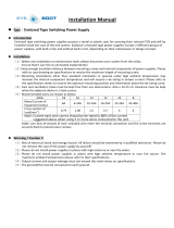
4.2 Characteristics (at 230 V)
ILL00764-00
26
24
20
22
18
16
10
14
16
12
8
<Cooling Capacity Curve> <Cool Air Temperature Difference Curve>
23.4(13)
21.612)
19.8(11)
18.0(10)
16.2(9)
14.4(8)
12.6(7)
10.8(6)
9.0(5)
68(20)
77(25)
86(30)
95(35)
7.2(4)
Delta-T °F (°C)
Dry Bulb Temp. °F (°C)
Dry Bulb Temp. °F (°C)
Dry Bulb Temp. °F (°C)
Wet Bulb Temp. °F (°C)
Wet Bulb Temp. °F (°C)
(25)
77
(20)
68
(35)
95
(30)
86
(15)
59
(10)
50
Cooling Capacity (x10
3
Btu/h)
Relative Humidity (%)
30 40 50 60 70 80
Current Consumption (A)
Power Consumption (kW)
<Power Consumption Curve> <Current Consumption Curve>
3.5
3.0
2.5
2.0
1.5
68(20)
77(25)
86(30)
95(35)
68(20)
77(25)
86(30)
95(35)
(25)
77
(20)
68
Wet Bulb Temp. °F (°C)
(35)
95
(30)
86
(25)
77
(20)
68

Operation Section
15
4.3 Characteristics (at 208 V)
ILL00765-00
26
24
20
22
18
16
10
14
16
12
8
<Cooling Capacity Curve> <Cool Air Temperature Difference Curve>
23.4(13)
21.6(12)
19.8(11)
18.0(10)
16.2(9)
14.4(8)
12.6(7)
10.8(6)
9.0(5)
68(20)
77(25)
86(30)
95(35)
7.2(4)
Delta-T °F (°C)
Dry Bulb Temp. °F (°C)
Dry Bulb Temp. °F (°C)
Dry Bulb Temp. °F (°C)
Wet Bulb Temp. °F (°C)
Wet Bulb Temp. °F (°C)
(25)
77
(20)
68
(35)
95
(30)
86
(15)
59
(10)
50
Cooling Capacity (x10
3
Btu/h)
Relative Humidity (%)
30 40 50 60 70 80
Current Consumption (A)
Power Consumption (kW)
<Power Consumption Curve> <Current Consumption Curve>
3.5
3.0
2.5
2.0
1.5
68(20)
77(25)
86(30)
95(35)
68(20)
77(25)
86(30)
95(35)
(25)
77
(20)
68
Wet Bulb Temp. °F (°C)
(35)
95
(30)
86
(25)
77
(20)
68

Operation Section
16
5. REFRIGERANT SYSTEM
5.1 Refrigerant System Construction
The component parts of the refrigerant system include the following:
• Compressor, Evaporator, Condenser, Capillary tube, High Pressure Switch
These parts are all connected by copper tubing. All the connections have been brazed.
ILL00766-00
Condenser
Condenser Outlet Pipe
Condenser Inlet Pipe
Compressor Discharge Pipe
Compressor
Compressor Suction Pipe
Capillary Tube
High Pressure Switch
Evaporator Outlet Pipe
Evaporator Pipe
Evaporator
Flow of
Refrigerant
Compressor
Evaporator
Accumulator
Condenser
Fan
Motor
Capillary
Tubes

Operation Section
17
5.2 Compressor
• The compressor used for the unit is hermetically sealed. The compressor and the compressor
motor are in one casing.
(1) Compressor construction
•The construction of a rotary type compressor is divided into two mechanisms; the drive
mechanism (compressor motor), and the compression mechanism (compressor). When the
rotor shaft of the motor (drive mechanism) turns, the roller (compression mechanism) rotates to
compress the refrigerant.
I001675
To Condenser
Accumulator
Strainer
From Evaporator
Blade
Discharge Valve
Oil
Lubricator
Roller
Cylinder
Rotor
Stator
Terminal

Operation Section
18
(2) Basic compressor operation
•The roller (compression mechanism) is set
eccentrically with a certain distance given from
the axis of the center of the cylinder. A spring
loaded blade is mounted on the cylinder. The
roller turns to compress the refrigerant in the
space between the cylinder and eccentrically
mounted roller. The blade is in contact with the
roller by means of spring force. The blade
partitions the space between the suction side
and the discharge side to keep compressed refrigerant from returning to the suction side. There
is no suction valve. The discharge valve is designed not to open until the pressure of the
refrigerant within the cylinder reaches or exceeds discharge side pressure. As a result, the
discharge valve prevents the backward flow of refrigerant gas.
I000510
Discharge
Hole
Cylinder
Blade
Spring
Suction
Hole
Discharge
Valve
Shaft
Roller

Operation Section
19
(3) Operation
1) Start of compression
1) The cylinder is filled with low pressure gas.
2) Since pressure in the discharge chamber is
higher than in the cylinder, the discharge
valve is kept closed.
2) Suction and compression
1) The pressure in the cylinder increases
gradually.
2) Refrigerant suction begins on the suction
side of the cylinder.
3) The discharge valve remains closed.
3) Discharge
1) The pressure in the cylinder exceeds that in
the discharge chamber, and the discharge
valve opens.
2) On the suction side, refrigerant suction
continues.
4) Completion of compression
1) When compression is completed, all of the
refrigerant has been drawn from the suction
chamber.
2) Operation then returns to step 1) (Start of
compression) and the above process of
suction and compression continues
repeatedly in succession.
I001676
Blade
Discharge
Valve
Roller
I001677
Blade
Discharge
Valve
Roller
I001678
Blade
Discharge
Valve
Roller
I001679
Blade
Discharge
Valve
Roller

Operation Section
20
(4) Compressor lubrication
•The lubrication system is comprised of a hollow
shaft, an oil scraper mounted at the end face,
hollow shaft, a shaft journal (shaft bearing),
and the lubrication groove for the shaft journal.
The lubrication groove is wider than the oil
hole. When the shaft turns, oil is scraped
upward by the oil scraper along the inside
diameter of the hollow shaft. The oil is fed
through the oil hole by centrifugal force, then
supplied to the lubrication groove for each
shaft journal, lubricating the bearing. In this
lubrication system, oil enters into each bearing
separately and returns to the oil reservoir. This
system effectively prevents bearing
temperature increases, and offers high
reliability. In addition, the specially treated
shaft journal keeps the bearing from being damaged during high temperature operation.
5.3 Condenser
• The condenser is a heat exchanger with copper tubes that are covered with thin aluminum
projections called plate fins.
• Heat is given off and absorbed by air being pulled across the condenser fins by the centrifugal
fan and then expelled through the exhaust air duct.
5.4 Capillary Tube
• The capillary tube is a long thin tube utilizing
line flow resistance to serve as an expansion
valve. The length and the inner diameter of the
capillary tube are determined by the capacity of
the refrigeration system, specified operating
conditions, and the amount of refrigerant. The
capillary tube causes the high pressure, high
temperature liquid refrigerant sent from the
condenser to expand rapidly as the refrigerant
is sprayed out through the fixed orifice in the capillary tube. As a result, the temperature and
state of the refrigerant becomes low and mist-like respectively, causing it to evaporate easily.
I001680
Oil Feed Groove
Oil Hole
Oil Scrapper
Roller
Rotor
Cylinder
Hollow Shaft
Eccentric Shaft
I001887
High Temp./High Pressure
Liquid Refrigerant
Low Temp./Low Pressure
Gas and Liquid Mixture
/