Page is loading ...

1
WARNING
3000 Series
3100 Series
3300 Series
3400 Series
IMPORTANT NOTICE
VacuFlush sanitation systems must be installed according to Dometic’s recommended
procedures. Do not attempt installation without rst contacting a VacuFlush Certied
Dealer, your nearest VacuFlush Parts Distributor, or Dometic.
This manual must be read and understood
before adjustment, maintenance, or service
is performed. Modication of this product
can result in property damage.
WARNING
!
SeaLand
®
ALL-CERAMIC VACUUM TOILET
OWNER’S MANUAL
VacuFlush
®
3000, 3100, 3300, 3400 Series Toilets
Dometic Sanitation Corporation
13128 State Rt 226, PO Box 38
Big Prairie, OH 44611
SeaLand Product Customer Service: 1-800-321-9886
www.DometicUSA.com

2
TABLE OF CONTENTS
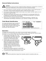
The model identication label is located on the inside wall
of the toilet under the tank access cover. It will show the
model number and serial number.
TOILET MODEL IDENTIFICATION
WARNING – ELECTRICAL SYSTEM.
Turn off electrical power before servicing.
WARNING – MOTOR STARTS AUTOMATICALLY.
Turn off electrical power before servicing.
Read and understand the complete contents of this manual before operating or servicing the sanitation
system. Failure to follow any precautions may result in damage to the sanitation system.
CAUTION – System may contain vacuum after shut-down.
Toilet Model Identication . . . . . . . . . . . . . . . . . 2
Important Information Before Operation . . . . . . 2
Operating Instructions . . . . . . . . . . . . . . . . . . . . 3
Flush Operation Timing Chart . . . . . . . . . . . . . . 4
Cleaning – Toilet Bowl and Seal . . . . . . . . . . . . 4
Winterizing . . . . . . . . . . . . . . . . . . . . . . . . . . . . 4
Clearing Discharge Lines . . . . . . . . . . . . . . . . . 5
Maintenance Schedule . . . . . . . . . . . . . . . . . . . 5
Spare Parts . . . . . . . . . . . . . . . . . . . . . . . . . . . . 5
Ordering Parts . . . . . . . . . . . . . . . . . . . . . . . . . . 5
Sanitation System Components . . . . . . . . . 6 – 7
Deodorants and Special Tissue . . . . . . . . . . . . 8
Marine Sanitation Regulations . . . . . . . . . . . . . 8
Flush Mechanism Components . . . . . . . . . . . . . 9
Manual Flush Operations . . . . . . . . . . . . . . . . 10
Electrical Specications . . . . . . . . . . . . . . . . . . 10
Troubleshooting . . . . . . . . . . . . . . . . . . . . .11 – 14
RV Wiring Diagrams . . . . . . . . . . . . . . . . 15 – 16
Marine Wiring Diagrams . . . . . . . . . . . . . 17 – 21
Dimensions . . . . . . . . . . . . . . . . . . . . . . . . . . . 21
Customer Service . . . . . . . . . . . . . . . . . . . . . . 22
WarrantY . . . . . . . . . . . . . . . . . . . . . . . . . . . . . 24
IMPORTANT INFORMATION BEFORE OPERATION
1. Fill freshwater tank and add deodorant to holding tank through toilet bowl.
2. Make sure all guests understand toilet operation and that the ushing instruction label is easy for guests to read.
This label (see below) is located under the seat, and is easily seen when the seat is raised.
3. Remember, the vacuum pump starts automatically. Shut off the toilet system before servicing and do not leave the
boat with toilet system breaker on.
4. Never use drain openers, alcohol, solvents, etc. in the system.
5. If the system does not function properly, refer to the Troubleshooting section of this manual and repair as
necessary. If problem persists, contact your local SeaLand dealer or see the Customer Service section of this
manual.
1. To add water to bowl before
using (if necessary), raise ush
handle until desired water
level is reached. (Water
ow will stop automatically
after a period of time).
2.
To ush, press ush handle down. Water
will ow into bowl for two seconds, then
ush ball will open. Toilet will not ush
again until “OK to Flush” light is on.
3. Do not dispose of sanitary
napkins or other non-dissolving
items in toilet, such as facial
tissue or paper towels.
These items can cause
plugging of the sanitation
system.

3
ACCESS COVER
CONTROL SWITCHES
OPERATING INSTRUCTIONS
1. Adding More Water To Toilet Bowl
Raise ush handle or press “Add Water” switch until desired
water level is attained. To prevent toilet overow, the control
module limits the amount of water that can be added.
2. Flushing The Toilet
When the vacuum status panel’s green “OK to Flush” light is
on, and the red “Do Not Flush” light is off, press the handle
or “Flush” switch down for a moment, then release it. Holding
the handle down will not prolong the ush cycle nor start a
new ush cycle. The handle must be allowed to return to the
“off” position and the vacuum must be allowed to recharge
before another ush cycle can be initiated. A full holding tank will also prevent the toilet from ushing.
3. Selecting Automatic Water Rell Levels:
The Water Level switch is located under the access cover. Carefully lift up on the front of the cover to access the
Water Level switch. There are three water rell levels available. The microprocessor-controlled water valve will
rell the toilet bowl according to your water level selection.
To reinstall the access cover, set the cover on top of the
toilet and press down. This will lock the cover in place
and prevent it from coming loose during travel.
LOW Level
Use this setting to conserve water. This position
reduces the chance of water splashing out of the bowl
during rough travel. If more water is needed for ushing,
lift up on the ush handle. Water ow will stop after
nine seconds to prevent overow.
MID Level
Use this position to keep the toilet bowl clean, especially when family and friends may be using the toilet.
If more water is needed for ushing, raising the ush handle will provide up to six seconds of rell time.
HIGH Level
Use this position if the MID level does not provide a clean toilet bowl. This position is not recommended while
underway. If more water is still desirable for ushing, raising the ush handle will provide up to three seconds
of additional water rell time.
4. Mode Switch
The Mode switch is located on the right side of the control module. It switches between three function settings:
NORMAL
Use this setting for ushing the toilet.
SERVICE
Use this position for cleaning the toilet bowl and ush ball seal. The ush ball will open automatically and remain
open in this position. Lifting up the ush handle provides water.
MANUAL OVERRIDE
Use this position to ush the toilet manually in the event of power or battery failure. This switch disconnects the
electronic brake in the ush valve motor, and allows manual ushing via the override access hole in the side
of the vitreous china base.
Note: The control module allows 15 seconds of water for cleaning. If more water is required, return
the switch to the NORMAL position then back to the SERVICE position.
A safety circuit in the control module monitors ush ball operation. If foreign objects or low voltage prevent
the ush ball from closing, this circuit prevents personal injury or damage to the ush valve motor. If this
condition occurs, reset the control module by placing the Mode switch into the SERVICE position temporarily,
then returning it to the NORMAL position.
OFF
FLUSH
ADD WATER
TO BOWL
OFF
FLUSH HANDLE
REMOTE
SWITCH
STATUS
PANEL
See page 6 for all VacuFlush wall switches.

4
FLUSH OPERATION TIMING CHART
WINTERIZING
At the end of each season, the VacuFlush toilet system must be winterized for storage. The following procedure should be
used:
1. Pump out holding tank.
2. Thoroughly ush system with fresh water.
3. Drain freshwater tank.
4. Add freshwater antifreeze to freshwater tank.
5. Flush freshwater antifreeze and water mixture through toilet
and into the waste holding tank. Each installation is different
so amounts may vary. User discretion is required to assure
adequate protection.
6. Turn off electrical power.
CAUTION: The use of freshwater antifreeze that contains alcohol will result in damage to your
sanitation system. Only use propylene glycol freshwater antifreeze that does not contain alcohol.
PROPER CLEANING – TOILET BOWL AND SEAL
Fig. B
The VacuFlush toilet should be cleaned regularly for maximum sanitation and
operational efficiency. You can clean it just as you would a household toilet.
Do not use caustic chemicals, such as drain-opening types, as they will damage
the seals.
BOWL CLEANING: For stubborn stains, use SeaLand Toilet Bowl Cleaner (Fig. A). It’s
manufactured especially for use with VacuFlush toilets. In certain locations where water is
hard, a build-up of lime may dull the toilet bowl nish. Restore the shine with this cleaner.
If you cannot nd this brand in your area, contact SeaLand Product Customer Service for
your nearest dealer. If it is not available, you can also use Bar Keepers Friend
®
cleanser.
Please follow label instructions.
SEAL CLEANING: After an extended time, mineral deposits from hard water can build
up under the edge of the rubber bowl seal, resulting in a slow leakdown of water from the
bowl. To prevent this mineral build-up, periodically clean under the bowl seal with SeaLand
Toilet Bowl Cleaner (Fig. B).
1. Put Mode switch in SERVICE position. Flush ball will open automatically.
2. Apply cleanser onto a cleaning tool (small short-bristle brush, etc.), and scrub under
the seal. Make sure to push bristles between bottom of seal and top of ush ball
surface to scrub all parts of seal that come into contact with ush ball.
3. Wait 2-3 minutes.
4. Pull up on ush handle to let water ow into bowl. Use cleaning tool and water to
rinse away cleanser and loosened deposits. You can add water for up to 15 seconds
Flush and Forget
®
Cycle Time
Flush Cycle In Seconds
16
5 1284
1
7
11
6 13 159 143
10
2
0 2.5
Water Valve
Flush Valve
Low Rell
Normal Rell
High Rell
Begin Opening for 0.1 sec.
Wait for 0.1 sec.
Continue Opening
Held Open
Closing Time
Additional “Add Water” Time Allowance
“Add Water” Time Limits
“Add Water” Time In Seconds
5 1284
1
7
11
6 13 159 143
10
2 16
0 2.5
Water Valve
Low Position
High Position
Service Position
Normal Position
Fig. A
in the SERVICE position.
5. Put Mode switch in NORMAL position. Water will ow for a few seconds, then ush ball will close automatically. Water will
continue owing into bowl, making it ready for the next ush.
® Bar Keepers Friend is a registered trademark of SerVaas Laboratories Inc.

5
MAINTENANCE SCHEDULE
Maintenance intervals and normal parts replacement vary widely depending on numerous factors such as frequency
of system use, quality of ushing water, etc. The following chart is intended strictly as a general guide in keeping
the sanitation system 100% ready for any conditions of use.
Maintenance Procedure
Recommended
Date of Service
Parts Required
Toilet ush ball seal cleaning
Tighten toilet seat mounting
hardware
Monthly
Monthly (or as needed)
SeaLand Toilet Bowl Cleaner
N/A
ROUTINE MAINTENANCE
Replace duckbill valves in Vacuum
Pump or Vacuum Generator
Replace ush ball seal and ush
ball (if needed)
Every three years
Every three years
Duckbill Valve Kit
Flush Ball Seal
Flush Ball
MAJOR SYSTEM MAINTENANCE
SPARE PARTS
The following parts should be kept available at all times:
Description
Part Number
Quantity Where Used
Flush Ball Seal
Flush Ball
Water Valve
Vacuum Breaker Kit
Vacuum Switch Kit
1.5-inch Duckbill Valve Kit
(2 ea. per kit)
see parts list
see parts list
see parts list
see parts list
see parts list
see parts list
1
1
1
1
1
1
All-ceramic toilet
Vacuum generating system
ORDERING PARTS
Dometic is ready to assist you in the event service is required. Before calling, please have the following information
available. Your cooperation in having this information ready is appreciated and allows us to better meet your needs.
Please refer to the Parts Distributor list in the Customer Service section (page 22).
1. Toilet Model Number
2. Serial Number
3. Part Number, Description and Quantity (see parts list insert)
CLEARING DISCHARGE LINES
Sanitation hoses should be cleared if toilet will not be needed for an extended period of time (more than two weeks).
1. Fill toilet bowl with water and add 4 oz. (120 ml) of biodegradable laundry detergent (should
NOT contain bleach).
2. Flush toilet, holding pedal down for about two minutes. Close ush ball.
3. Turn off water supply to toilet.
4. Flush the toilet without water, allowing the vacuum pump to shut off after the ush. Repeat three times. (This proce
-
dure will minimize any remaining water in the sanitation hoses.)
5. Turn off power to the vacuum pump.
6. Completely pump out holding tank.
If system will be subjected to freezing temperatures, please follow above procedure, then winterize system as described
in this manual.

6
SANITATION SYSTEM COMPONENTS
Vacuum Toilet: VacuFlush all-ceramic vacuum toilets with
Flush and Forget
®
technology operate differently compared
to other toilets. The vacuum system uses a small amount of
water (a little more than a pint or .5 liter) per ush in addition
to a simple vacuum. The toilet is connected to a pressurized
freshwater system. Fresh water is the key to an odor-free
bathroom compartment. Most VacuFlush toilets are
equipped with an integral vacuum breaker which prevents
the possible contamination of the freshwater supply.
Flush/Add Water Switches (3100, 3400 models only):
Wall-mounted push-button switches provide electronic
operation of ushing and adding water to the toilet bowl.
Models include two-light vacuum status panel indicating the
toilet is “OK to Flush” or “Do Not Flush”. Models vary.
Vacuum Generator: The vacuum generator combines
the vacuum tank and vacuum pump in one unit. It greatly
reduces installation time and eliminates the hose run
between the tank and pump. Their compact size makes them
especially well-suited to smaller installation spaces.
Vacuum Tank: The vacuum tank stores vacuum energy.
System vacuum level is monitored by a vacuum switch
located on the vacuum tank. When this switch senses
a drop in vacuum in the system, it automatically signals
the pump to energize and bring the vacuum to operating
level. This process is normally completed in less than one
minute.
Vacuum Pump: The vacuum pump is an electric,
straight-through bellows type. It is manufactured of long-
lasting polypropylene and draws only 4 to 6 amps of current
at 12 VDC. This unique pump design is both an efcient air
and liquid pump that handles solids without a problem. It
has two duckbill valves on each side of the pump chamber
to maintain vacuum and prevent backow of waste.
“Tank Full” Shut-Down Switches (RV option only):
These “Tank Full” micro-oat switches shut down the
vacuum generator when the waste holding tank is full.
We offer three styles to accommodate various installation
requirements.
Sealing grommet style – Item number 900101
MPT style – Item number 900100
Vent style – Item number 900102
(NOTE: Requires relay mounted on vacuum generator.)
Vacuum Toilets
Vacuum Tank and
Vacuum Pump
RV “Tank Full”
Shut-Down
Switches
Sealing
grommet
style
MPT
style
Vent
style
Marine Flush/Add Water
Switches
Vimar Gewiss
Vacuum
Generators
RV Flush/Add Water
Switch
Dometic

7
SANITATION SYSTEM COMPONENTS (cont’d)
TankWatch
®
Level Indicator (marine option only):
The TankWatch unit utilizes micro-oat switches which
activate an indicator panel. The micro-oat switches are
installed in the top of the holding tank. The adjustable
probe assemblies are exible polybutylene tubing and are
designed to ex when tank contents move.
VacuStat™ Indicator Panel: Continuously moni-
tors vacuum status for proper toilet operation.
Brushed metallic finish complements bathroom
decor. Item number 700112 (12VDC).
Vacuum Status Panel (optional): A two-light status panel
indicates the system is “OK to Flush” or “Do Not Flush”.
The green “OK to Flush” light is illuminated when there is
adequate vacuum pressure available and when the holding
tank is less than full. Item number 710012.
VacuFlush Status Panel (optional): Includes two-light
status panel indicating the system is “OK to Flush” or “Do
Not Flush”, and circuit breaker to shut down system at night.
Item number 500012 (12 VDC) or 500024 (24 VDC).
Vacuum Generator Shut-down Relay (standard on RVs;
marine option): This relay can automatically shut down
power to the VacuFlush toilet system to prevent overl-
ling of the holding tank. Item number 310289 (12 VDC) or
310290 (24 VDC).
Vacuum Tester (optional): This tool assists in identifying
the location of vacuum leaks. The vacuum tester consists
of a vacuum gauge and a cone-shaped plug. Inserting the
plug in the inlet of the vacuum tank or vacuum generator
isolates the toilet from the system. In this way, a vacuum
leak can easily be located in either system. Item number
530002.
In-Line Vent Filter (marine option only): The SaniGard
TM
vent lter has special odor-removing lter materials to help
keep your vehicle smelling clean and pleasant. Heavier-
than-air malodors accumulate in the holding tank. This vent
lter has a special type of activated lter media to remove
these odors before they offend. Each cartridge is good for
an entire season, and is easily replaced for a fresh start.
Replacement cartridges are available.
Holding Tanks (marine option only – not shown):
SeaLand holding tanks are made of super-strong, 3/8”
(10mm) thick polyethylene — 50% thicker than most other
holding tanks. Each features solid, one-piece construction
with no seams for unmatched durability. A deodorant ad-
ditive is recommended to keep the holding tank odor-free.
See Deodorants and Special Tissue section for further
information (page 8).
Vacuum
Status Panel
Vacuum Tester
VacuStat Indicator Panel
Vent Filter
TankWatch
Panel and
Probes
VacuFlush
Status Panel

8
MARINE SANITATION REGULATIONS
All boats with xed toilets in U.S. waters and in the waters of some other countries are required to be equipped with an operable
marine sanitation device (MSD). The VacuFlush vacuum sanitation system, when installed in a boat, is a holding tank or Type
III system as dened by the U.S. Coast Guard. Type III systems are designed to permit operation of the toilet without the direct
discharge of untreated waste after every ush. This means onboard toilet facilities can be used when the boat is near swimmers,
beaches or shellsh beds.
Type III systems can be discharged at marina dockside pump-out stations or, if in coastal waters, a minimum of three miles
offshore. Overboard discharge capability must remain secured while within the three-mile limit. The overboard discharge
pump is activated by a keyed switch located in the toilet compartment. This key should be removed at all times except when
discharge pump is operating.
Sewage from any source should not be discharged directly into our waters. If you are interested in learning more about this issue,
please contact Dometic at the phone number or address listed on the back page of this manual.
DEODORANTS AND SPECIAL TISSUE
Your VacuFlush toilet and sanitation system require the regular addition of a deodorant product to reduce malodors and
to help break down holding tank contents. Several factors should be considered in selecting a deodorant product.
Liquid or Dry: Liquid products obviously work more quickly by readily going into solution. Granulated powder
formulations, on the other hand, have the advantage of requiring less storage space and are less likely to leak if the
package is inadvertently damaged.
Formaldehyde versus Non-Formaldehyde: Dometic manufactures both types of deodorants. Generally,
formaldehyde formulas control odor very effectively at all temperatures and with all degrees of water hardness.
SeaLand
®
Environment-Friendly brand, which is formaldehyde free, is similarly effective.
How Much Deodorant and How to Add It: The deodorant is added directly into the toilet bowl, then ushed into
the holding tank. Follow bottle or package instructions. Conditions of extremely warm weather, longer waste hold-
ing time and larger tank capacities may require more deodorant treatment. Also, to maintain optimum efciency in
odor control, the waste holding tank should be cleaned thoroughly at least once or more each season, depending
on use.
Why Not Use Household Toilet Paper in Your VacuFlush Toilet? Household tissues often contain adhesives
which bond together the paper bers from which the tissue is made. The adhesives prevent the tissue from breaking
apart, and their use in “ultra-low ow” systems can cause system clogging. SeaLand tissue is especially designed
for use in low water toilet systems. Its rapid dissolving properties minimize the amount of residual paper in the hold-
ing tank and allow deodorizers to work more efciently.
SeaLand versus Other Brands: SeaLand constantly strives to provide our system owners with effective products
that have minimal environmental impact and good value. Many deodorant products do not measure up to our
standards of performance and value.
SeaLand
®
Granulated
Deodorant
Six 2-oz. pouches
Part No.
379626002
SeaLand
®
Liquid
Deodorant
Two 8-oz. bottles
Part No.
379224008
SeaLand
®
Liquid
Deodorant -
Environment
Friendly
32-oz. bottle
Part No.
379114032
SeaLand
®
Rapid-Dissolving
Toilet Tissue
Four 400-sheet rolls
Part No.
379441204
SeaLand
®
Cleaner
16-oz. bottle
Part No.
379314016
SeaLand
®
Clean ‘n Green
Bowl Cleaner &
Tank Deodorant
12-2 oz. drop-in pouches
Part No. 379512602

9
FLUSH MECHANISM COMPONENTS
1. To a cc es s
base assembly
c o m p o n e n t s ,
remove decora-
tive screw caps
and unscrew the
bolts that hold
china toilet to
oor.
2. Remove access cover.
Lift up control module. Dis-
connect power cable and
vacuum control cable from
control module. Do not
disconnect flush handle
cable or base assembly
cable.
3. Lift china toilet
straight up and set it
down close to front of
oor ange/adapter
assembly. Turn off
water to toilet and
disconnect flexible
water line at rear of
base assembly. The
toilet is completely
disconnected.
Base Assembly
Cable
BASE ASSEMBLY COMPONENTS
(under china toilet)
Water Valve
Flush Ball
Closed Limit
Switch
Motor
Drive Arm
Rotor Arm
Flush Valve
Motor
Flexible Water Supply Hose
Open Limit
Switch
Discharge Adapter
(3048, 3148, 3348,
3448)
FLUSH HANDLE (3000, 3300 toilets)
(under Access Cover)
REMOTE FLUSH SWITCHES (3100, 3400 toilets)
Vimar switch - marine Gewiss switch - marine RV ush switch
Discharge Adapter
(3006, 3009, 3106, 3109,
3309, 3409)
Flush
Handle
Flush
Switch
Flush
Handle
Cable
Mode Switch
Water Level Switch
Input for Vacuum
Control Cable
Input for Flush
Switch Cable
Power
Cable
Input for
Base Assembly
Cable
CONTROL MODULE
Dometic switch - marine

10
MANUAL FLUSH OPERATION
In the event of an electrical failure, the ush ball can be manually operated to clear the bowl. We recommend using
a long-neck screwdriver or 7/16-in. socket for the operation shown below. NEVER PRY OPEN THE FLUSH BALL
FROM INSIDE THE TOILET BOWL. Damage to the ush ball and bowl seals may result.
2. Locate hole on left side
of china toilet. This al-
lows access to the ush
valve motor drive arm.
3. Insert screwdriver or
7/16-in. socket through
access hole and onto hex
head.
4. Turn screwdriver or
socket wrench counter-
clockwise. This will open
ush ball and allow bowl
contents to clear. After
bowl is clear, turn screwdriver or socket wrench clockwise
to return ush ball to original position.
1. Remove PC board
access cover. Place
Mode Switch in the
“Manual Override” posi-
tion. This disconnects
ush valve motor brake
from electrical circuit.
NOTES:
Water will not enter the toilet bowl during manual ush
operation.
Place Mode Switch in the “Normal” position before
returning to automatic operation.
Manual Override
position
TOILET SYSTEM ELECTRICAL SPECIFICATIONS
12VDC 24VDC
Maximum standby current (amps): .080 .080
Maximum operating current (amps): 6.5 2.5
Flush motor locked rotor current (amps): 14.5 7.25
Maximum voltage 15 30
Minimum voltage: 10 20
Input power wire size 14 ga. 14 ga.
All other wires size: 18 ga. 18 ga.
Fuse size (amps) 8 4
NOTES: Standby current includes ush panel status light.
Operating current does not include vacuum pump or other sanitation system components.

11
TROUBLESHOOTING
A volt/ohmmeter (VOM) and the appropriate Toilet Wiring Diagram may be required for this section.
Caution: Portions of this section will require that power be applied to the toilet. Keep hands away from
the ush ball, motor drive arm and rotor shaft to prevent personal injury during testing and troubleshooting.
The control module uses a microprocessor to provide all the automatic and timing functions. The control module
is on the right side under the access cover on the top of the toilet. The control module has input and output status
lights that can be used in troubleshooting the toilet.
The program in the microprocessor monitors the input and output signals during a normal ush cycle. If the inputs
or outputs do not follow the commands of the program, then the microprocessor may go into a “standby” mode and
ash an “error code.” The microprocessor is reset by placing the Mode switch in the SERVICE position temporarily,
then returning the switch to the NORMAL position.
A safety circuit in the control module monitors ush ball operation. If foreign objects or low voltage prevent the ush
ball from closing, this circuit prevents personal injury or damage to the ush valve motor. If this condition occurs,
reset the control module by placing the Mode switch into the SERVICE position temporarily, then returning it to the
NORMAL position.
CONTROL MODULE STATUS LIGHTS
Status Light
10 OK to Flush
11 Do Not Flush
11 Do Not Flush
11 Do Not Flush
11 Do Not Flush
ERROR CODES
Condition
Mode Switch in SERVICE position
VALVE OPEN Limit Switch problem
VALVE CLOSED Limit Switch problem
Insufcient vacuum in system
Flush valve motor relay failure
No. of Flashes
1
1
2
3
4
Pause
.5 sec.
2 sec.
2 sec.
2 sec.
2 sec.
Status Light
1 Low Level
2 High Level
3 Valve Closed
4 Valve Open
5 Service Mode
6 Flush
7 Add Water
8 High Vac Switch
9 Holding Tank Full
10 OK to Flush
11 Do Not Flush
12 Water Valve
13 +5V
Function
Water Level Switch in “Low” position.
Water Level Switch in “High” position.
Flush valve Closed Limit Switch engaged.
Flush valve Open Limit Switch engaged.
Mode Switch in “Service” position.
Flush Switch on control panel engaged.
Add Water Switch on control panel engaged.
High vacuum in system (allows toilet to ush).
Full holding tank (prevents toilet from ushing).
Signal to “OK TO FLUSH” light on control panel.
Signal to “DO NOT FLUSH” light on control panel.
Electric water valve energized.
Input power present.
VALVE CLOSED
VALVE OPEN
SERVICE MODE
FLUSH
ADD WATER
HI VAC SWITCH
HOLD TANK FULL
OK TO FLUSH
DO NOT FLUSH
HI LEVEL
LO LEVEL
WATER VALVE
+5V
LED 13
LED 12
LED 11
LED 10
LED 9
LED 8
LED 7
LED 6
LED 5
LED 4
LED 3
LED 2
LED 1

12
TROUBLESHOOTING (cont’d)
SYMPTOM 1. Toilet will not ush and water will not enter toilet bowl.
Condition
Mode Switch in SERVICE position.
Valve Open Limit Switch problem.
Valve Closed Limit Switch problem.
Insufcient vacuum in system.
Flush valve motor relay failure.
Corrective Action
Return Mode Switch to NORMAL position.
With the ush valve fully open, check the “VALVE OPEN” status light. If
the light is off, then the Valve Open Limit Switch is out of alignment or
defective, or related wiring is defective.
With ush valve in the fully closed position check the “VALVE CLOSED”
status light. If the light is off, then the Valve Closed Limit Switch is out
of alignment or defective, or related wiring is defective.
Check the “HI VAC” status light. If the light is off, the signal from the vac-
uum switch located on the vacuum generator or vacuum tank is absent
and preventing the toilet from ushing in the NORMAL mode. Check
for loss of power to the vacuum generator or vacuum pump. Check for
loose or defective wiring between the vacuum switch and the toilet.
Replace control module.
ERROR CODE CORRECTIVE PROCEDURES
TOILET OPERATION
Condition
+5V status light is off (on far
right of control module):
+5V status light is on:
Corrective Action
• Check toilet fuse or circuit breaker at DC distribution panel.
• Check for loose or defective wiring between control module and DC
distribution panel.
• Check for reverse polarity of input power to control module.
• If all of above check OK, replace control module.
• Input power must be 10 volts or higher.
• Check control module for error codes.
• Check “HI VAC” status light. If light is off, vacuum is low, preventing
the toilet from ushing.
• Check “HOLD TANK FULL” status light. If light is on, black water
holding tank is full, preventing toilet from ushing.
• Put Mode Switch in SERVICE position. If ush valve opens, go to
next step. If the ush valve does not open, go to Symptom 2.
• Put the Mode Switch in NORMAL position and push ush handle
down while observing “FLUSH” status light. The “FLUSH” status
light must come on when the handle is pressed and go off when the
handle is released. If the “FLUSH” status light did not follow com-
mands of handle, then ush switch or related wiring is defective.
SYMPTOM 2. Flush valve will not open when the Mode Switch is in the SERVICE position or when
the ush handle is pushed while in the NORMAL position.
Procedure
Check the voltage output
to the ush valve motor at
jack 6, pins 9 and 10 on the
control module as follows:
Corrective Action
• Pull the control module out as far as the control cables will allow.
Locate jack 6 at the bottom of the control module.
• Remove the purple wire from pin 6.
• With DC voltmeter test leads across pins 9 and 10, ip the Mode
Switch between the NORMAL and SERVICE positions. If voltage is
present for about two seconds in the SERVICE position, the ush
valve motor or related wiring is defective. If voltage is not present,
replace the control module.

13
TROUBLESHOOTING (cont’d)
SYMPTOM 3. Flush valve will not close.
Condition/Procedure
Mode Switch is in SERVICE
position:
Foreign object prevents the ush
valve from closing and the safety
circuit locked ush valve in open
position:
Check for error code at “DO NOT
FLUSH” status light.
Check the voltage output to
the ush valve motor at jack 6,
pins 9 and 10 on the control
module as follows:
Corrective Action
• Return switch to the “Normal” position.
• Reset the control circuit by putting the Mode Switch in the SERVICE
position temporarily, then returning to the NORMAL position. If the
ush valve did not close, go to next step.
• If showing error, follow the instructions in the Error Code Corrective
Procedures section.
• Pull the control module out as far as the control cables will allow.
Locate jack 6 at the bottom of the control module.
• Remove the green wire from pin 5.
• With DC voltmeter test leads across pins 9 and 10, ip the Mode
Switch between the SERVICE and NORMAL positions. If voltage is
present for about two seconds in the NORMAL position, the ush
valve motor or related wiring is defective.
• If voltage is not present, replace the control module.
SYMPTOM 4. Water will not enter toilet bowl during a ush and when the ush handle is raised
in the “Add Water” position.
Procedure
Place the Water Level switch
in the LOW position. Check
the “WATER VALVE” status
light while pressing the ush
handle down:
Corrective Action
• If the “WATER VALVE” status light comes on, the water valve lter
screen may be plugged with debris, or the water valve or its related
wiring is defective.
• If the “WATER VALVE” status light remains off, replace the control
module.
• If voltage is not present, replace the control module.
SYMPTOM 5. Water will not enter toilet bowl when the ush handle is raised in the “Add Water”
position.
Procedure
Flush the toilet, then place
the Water Level switch in the
LOW position. Then check
the “LO LEVEL” status light
while raising the ush handle:
Corrective Action
• If the “LO LEVEL” status light comes on, replace the control module.
• If the “LO LEVEL” status light does not come on, the ush switch or
its related wiring is defective.
SYMPTOM 6. Water Level switch has no effect on water level in the “Low” or High” position.
Corrective Action
• Replace control module.
SYMPTOM 7. Flush valve will not open when Mode Switch is in the “Service” position but opens
during a normal ush cycle.
Corrective Action
• Replace control module.

14
TROUBLESHOOTING (cont’d)
SYMPTOM 8. Water will not stay in bowl and system loses vacuum.
Condition/Procedure
Put Mode Switch in “Service”
position:
Worn or damaged ush valve ball
and seal:
Corrective Action
• Clean underside of ush valve ball seal of dirt and debris.
• Remove toilet from oor and remove base assembly from toilet and
replace ush valve ball and seals.
SYMPTOM 9. Water will not shut off and overows the toilet.
Procedure
Check the “WATER VALVE” status
light:
Corrective Action
• If the light is on when not ushing the toilet or adding water, replace
the control module. If the light responds correctly, go to next step.
• Dirt or debris lodged in the water valve seal. Remove the toilet from
the oor, disassamble and clean water valve.
• Replace water valve.
SYMPTOM 10. Water is leaking from under the toilet.
Procedure
Remove the toilet from the
oor and inspect the following
with both water and electrical
power applied:
(place a container under the base
assembly to catch any water during
the inspection procedure)
• Water hoses and ttings, water valve assembly
• China toilet bowl
• Upper base seal
• Flush valve ball rotor shaft shaft
• Base assembly
SYMPTOM 11. System leaks vacuum, but water remains in toilet bowl.
Procedure
Remove the toilet from the oor
and insert a plug or vacuum tester
into the discharge port of the oor
ange or discharge adapter:
Corrective Action
• If the vacuum leaks stops, go to the next step. If the vacuum leak
continues, the leak is in the discharge plumbing and not the toilet.
• Inspect the O-ring around the bottom of the base. Replace if defec-
tive.
• Inspect the inside surface of the discharge adapter or oor ange for
grooves or scratches that may interfere with the O-ring seal. Replace
if defective.
• If all of above appear normal, then the leak is most likely the rotor
shaft O-rings. Replace the rotor shaft.

15
RV WIRING DIAGRAMS
RV VACUFLUSH TOILET – FLUSH HANDLE (3000, 3300 SERIES)
RV VACUFLUSH TOILET – REMOTE FLUSH SWITCH (3100, 3400 SERIES)
REMOTE FLUSH SWITCH
(3100, 3400 series RV toilets)

16
RV WIRING DIAGRAMS (cont’d)
RV VACUFLUSH STATUS PANEL OPTION
RV VACUSTAT PANEL OPTION

17
MARINE WIRING DIAGRAMS
MARINE VACUFLUSH TOILET – FLUSH HANDLE (3000, 3300 SERIES)
MARINE VACUFLUSH TOILET – GEWISS FLUSH SWITCH (3100, 3400 SERIES)
GEWISS FLUSH SWITCH OPTION
(3100, 3400 series marine toilets)

18
MARINE WIRING DIAGRAMS (cont’d)
MARINE VACUSTAT PANEL OPTION
VIMAR FLUSH SWITCH OPTION
VIMAR FLUSH SWITCH OPTION
(3100, 3400 marine toilets)

19
VACUFLUSH STATUS PANEL OPTION
MARINE WIRING DIAGRAMS (cont’d)
IMPORTANT: ORANGE WIRE ON PIN 15 OF CONTROL
MODULE MUST BE CONNECTED TO THE “A” TERMINAL OF
THE VACUUM SWITCH REGARDLESS OF WHICH VACUUM
SOURCE IS USED.
MARINE VACUFLUSH STATUS PANEL / TANKWATCH OPTION

20
M-SERIES VACUUM PUMP AC CIRCUIT OPTION
MARINE WIRING DIAGRAMS (cont’d)
VACUUM GENERATOR/VACUUM TANK AND PUMP OPTION
/