
NOT A WALKWAY
NOT A WALKWAY
C
L
A
S
S
C
E
R
T
I
F
I
ED
T
O
C
A
N
/CS
A
C
2
2
.
2
N
O
.
247
C
O
N
F
O
R
MS
T
O
A
N
S
I
/
U
L
-
3
2
5
V
E
H
I
C
U
L
A
R
G
A
TE
O
P
E
R
A
T
O
R
H
P
5
3
38
2
M
O
D
E
L
S
E
R
I
A
L
V
O
L
T
SP
H
A
S
E
A
MP
S
6
0
H
z
M
A
X
G
A
T
E
L
O
A
D
Do
o
r
K
i
n
g
,
I
n
c
.
,
I
n
g
l
e
w
o
od
,
C
A
M
OV
I
N
G
A
RM
c
an
ca
us
e
v
e
hi
cl
e
d
am
a
g
e
,
s
er
i
o
us
i
n
j
ur
y
o
r
de
a
th
.
S
TA
Y
C
L
EA
R
o
f
a
r
m
a
t
al
l
t
i
m
e
s
.
NO
:
Pedes
t
r
i
a
ns
Bi
c
y
c
l
e
s
M
o
t
or
cy
c
les
WA
R
NI
NG
Mo
vi
n
g
G
a
te
C
a
n
C
a
u
se
Ser
i
o
u
s In
j
u
r
y
o
r
D
e
a
th
KEEP
C
L
EAR
!
G
at
e
ma
y
mo
ve
a
t
a
n
y
t
i
me
w
i
t
h
o
u
t
p
ri
o
r
w
a
rn
i
n
g
.
D
o
n
o
t
l
e
t
ch
i
l
d
re
n
o
p
e
ra
te
t
he
g
a
t
e
o
r
p
l
a
y
i
n
t
h
e
g
a
te
a
re
a
.
T
h
i
s
e
n
tra
n
ce
i
s
f
o
r
vehi
cl
e
s
o
n
l
y.
Pe
d
e
st
ri
a
n
s
mu
st
u
se se
p
a
ra
t
e
e
n
t
ra
n
ce.
M
OV
I
N
G
A
R
M
c
a
n
ca
u
se
v
e
h
ic
l
e
d
a
ma
g
e
,
se
r
iou
s
i
nj
u
r
y
o
r
d
e
a
t
h.
S
T
A
Y
C
L
EA
R
o
f
a
r
m
a
t
a
ll
tim
e
s
.
N
O:
P
e
d
e
s
t
r
ia
n
s
Bi
c
yc
l
e
s
Mo
to
r
c
y
c
le
s
WA
R
N
IN
G
THIS PRODUCT IS TO BE INSTALLED AND SERVICED BY A TRAINED GATE/DOOR SYSTEMS TECHNICIAN ONLY.
Visit
www.doorking.com/dealer-locator
to find a professional installing and servicing dealer in your area.
Used with 1601 Barrier Gate Operator
WITHOUT Convenience Open,
WITH Manual Release
to Enhance Vehicular Traffic
Control Management
Installation Manual
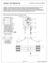
1620 Lane Barrier Add-On
1620 Lane Barrier Add-On
1620 Lane Barrier Add-On
1620 Lane Barrier Add-On
Surface Mount Vehicular Lane Barrier Accessory
Copyright 2020 DoorKing
®
, Inc. All rights reserved.
The 1620 lane barrier is not a stand-alone product. It must
be used with a 1601 Barrier Gate Operator (sold separately).
The 1620 is not crash rated. It is intended to provide a more
formidable barrier in conjunction with a standard barrier
arm operator system. The 1620 is ideally used to control
passenger vehicles and light-duty trucks.
IMPORTANT: Installation of Traffic
Light, Photocell and Octagon
Arm with Reverse/LED Edge is
REQUIRED.
Use this manual for circuit board 1601-010 Revision W or higher.
1620-065-G-8-20


1620 Models
Table of Contents
Secondary Barrier Arm
1601 Barrier Operator
(sold separately)
Lane Width
IMPORTANT: Secondary barrier arm is a
fixed distance for each lane width model.
9 ft Lane - P/N 1620-080
2 - 3ft Arm Channel Sections
1 - 2ft Arm Channel Section
2 - End Caps
Secondary Barrier Arm 9ft Assembly
30 Counterweights (1620-050)
10 ft Lane - P/N 1620-081
3 - 3ft Arm Channel Sections
2 - End Caps
Secondary Barrier Arm 10ft Assembly
32 Counterweights (1620-052)
12 ft Lane - P/N 1620-083
3
- 3ft Arm Channel Sections
1 - 2ft Arm Channel Section
2 - End Caps
Secondary Barrier Arm 12ft Assembly
32 Counterweights (1620-054)
14 ft Lane - P/N 1620-085
3
- 3ft Arm Channel Sections
2 - 2ft Arm Channel Sections
2 - End Caps
Secondary Barrier Arm 14ft Assembly
34 Counterweights (1620-058)
1
2
3-4
5
6
7
8
9
10
11
12
DoorKing Safety for Lane Barrier
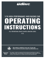
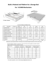
Safety and Traffic Management for Lane Barrier System
Layout
Entry Lane Only In-Ground Loop Options
Install Traffic Light (Required)
Install Octagon Arm
Install Photocell (Required)
Opening Operation (Green Lights)
Closing Operation (Red Lights)
Manual Release Operation
Operator Factory Wiring and ALL REQUIRED Components Wiring
Arm Channel Section
End
Cap
One-Way Traffic Direction ONLY!
IMPORTANT: Installation of Octagon Arm with Reverse/LED Edge, Traffic Light and Photocell is REQUIRED.
Octagon Arm with
Reverse/LED Edge
Photocell
Traffic
Light

1
1620-065-G-8-20
Moving Gate Can Cause
Serious Injury or Death
KEEP CLEAR! Gate may move at any time
without prior warning.
Do not let children operate the gate or play
in the gate area.
This entrance is for vehicles only.
Pedestrians must use separate entrance.
DoorKing Safety for Lane Barrier
NOT A WALKWAY
WA
LKWAY
C
L
A
S
S
C
E
R
T
I
F
I
E
D
T
O
C
A
N
/
C
S
A
C
2
2
.
2
N
O
.
2
4
7
C
ON
F
O
R
M
S
T
O
A
N
S
I
/
U
L
-
3
2
5
VE
H
I
C
U
L
A
R
G
A
T
E
O
P
E
R
A
T
O
R
H
P
5
3
3
8
2
M
O
D
E
L
S
E
R
I
A
L
V
O
L
T
S
P
H
A
S
E
A
M
P
S
6
0
Hz
M
A
X
G
A
T
E
L
O
A
D
D
o
o
r
K
i
n
g
,
I
n
c
.
,
I
n
g
l
e
w
o
o
d
,
C
A
MO
V
I
N
G
A
R
M
c
a
n
c
a
u
s
e
v
e
h
i
c
l
e
d
a
m
a
g
e
,
s
e
r
i
o
u
s
i
n
j
u
ry
o
r
d
e
a
t
h
.
S
T
AY
C
L
EAR
o
f
a
r
m
a
t
a
l
l
t
i
m
e
s
.
N
O
:
P
ed
e
s
tr
ia
n
s
B
i
c
y
c
l
e
s
M
o
t
o
r
c
y
c
l
e
s
WA
RNI
NG
Mo
vi
n
g
Ga
te
Ca
n
Ca
u
se
S
e
riou
s In
ju
ry
o
r
Dea
th
K
E
E
P
CLE
A
R!
G
ate
ma
y
mo
ve
a
t
a
n
y
ti
me
w
i
th
o
u
t p
r
i
o
r
wa
r
n
i
n
g
.
D
o
n
ot
l
e
t c
hi
l
d
r
e
n
o
p
e
rate
the
g
a
te
o
r
p
l
a
y
i
n
th
e
g
a
te
a
re
a.
T
h
i
s
e
n
tr
a
nce
i
s fo
r
veh
i
c
l
e
s
o
nly
.
P
ede
str
i
a
n
s
mu
s
t use
s
ep
a
r
ate
en
tr
a
n
ce.
IMPORTANT: A lane barrier gate operator installed WITHOUT any
external safety sensors CANNOT sense a person under the raised
arm and can strike them while the arm is lowering.
This scenario is VERY DANGEROUS and MUST NEVER OCCUR!!
When the photo beam gets
interrupted by a pedestrian, a
lowering arm will reverse and raise.
Photo Sensor
• DKS Lane Barrier System is NOT crash rated. It is intended to provide a formidable barrier to help
prevent passenger vehicles and light-duty trucks from driving through a controlled traffic lane.
• Lane barrier MUST have reverse/LED edge on arm, traffic light and photoelectric cell functioning or
remove lane barrier from service until repairs have been made.
• Make sure all warning signs are on operator and arm. They MUST be easily visible.
• Do not install the operator in such a way that the arms moves within 16 inches of a rigid object
or 10 feet from high voltage power wires with arm in the raised position.
• Speed limit through barrier area is 5 MPH. Install speed bumps, warning signs and hazard stripes
where visible in the area of the lane barrier gate, failure to do so may result in injury, damage to
operator and vehicle.
• Users should be familiar with proper use of operator, these include; hardware operation, reversing
functions and testing, reversing loops, inherent reversing system, electric edges, photoelectric cells
related external devices and possible hazards.
• Keep adults, children and objects away from operator and HAZARD ZONES.
•
Automotive ONE-WAY traffic only - No bicycles or motorcycles.
Pedestrians MUST be provided with separate access.
• All electrical connections should be made in accordance with local electrical codes.
• Security features should be installed to avoid unauthorized use.
• Controls intended for user activation must be located at least six feet (6') away from any moving
part of the barrier gate and where the user is prevented from reaching over, under or around the lane
barrier gate to operate the controls. Emergency access controls only accessible by authorized
personnel (e.g., fire, police, EMS) may be placed at any location in the line-of-sight of the lane barrier
gate.
• When manually operating the gate operator arms, the user MUST make sure that the gate area is
clear BEFORE operating the controls. Any activity in the traffic lane should be monitored to ensure a
safe operation when opening or closing the lane barrier gate. The motion of the barrier arms must be
directly observable by the person operating the lane barrier. While barrier arms are in motion
NO pedestrian and NO vehicle shall be in the immediate vicinity of the lane barrier area.
• When removing the operator from service, move the arms to the full open
position and shut off power at the service panel.
• Operators and components should be properly installed and
maintained following the recommended service schedule,
test the operator monthly. Keep all debris out of arm
channel and from operator housing vents and off of
arms. Contact your service dealer for any
maintenance or repairs.
• Vehicular lane barrier gate operator can produce high
levels of force, it is important that you are aware and
eliminate possible HAZARDS; Pinch Points, Entrapment
Areas, Overhead Power Wires, Absence of Controlled
Pedestrian Access, Traffic Backup.
OT
N

2
1620-065-G-8-20
Safety and Traffic Management for Lane Barrier System
NOT A WALKWAY
A
WALKWAY
C
L
A
S
S
C
E
R
T
I
F
I
E
D
T
O
C
A
N
/
C
S
A
C
2
2
.
2
N
O
.
2
4
7
C
O
N
F
O
R
M
S
T
O
A
N
S
I
/
U
L
-
3
2
5
V
E
H
I
C
U
L
A
R
G
A
T
E
O
PE
R
A
T
O
R
H
P
5
3
3
8
2
M
O
D
E
L
S
E
R
I
A
L
V
O
L
T
S
P
H
A
S
E
A
M
P
S
6
0
H
z
M
A
X
G
A
T
E
L
O
A
D
D
o
o
r
K
i
n
g
,
I
n
c
.
,
I
n
g
l
e
w
o
o
d
,
C
A
M
O
V
IN
G
A
R
M
c
a
n
c
aus
e
v
e
h
i
c
l
e
d
a
m
age
,
s
e
r
i
o
u
s
i
nj
u
r
y
o
r
d
e
at
h.
S
T
A
Y
CL
E
A
R
of
ar
m
a
t
a
l
l
t
i
m
es
.
N
O:
P
e
des
t
r
ia
n
s
B
i
c
y
c
l
e
s
M
o
t
o
r
c
y
c
l
e
s
W
ARNI
NG
M
o
v
i
n
g
G
a
te
C
an
Ca
us
e
S
er
i
o
us
Inj
u
r
y
or Deat
h
K
EE
P
C
LE
A
R
!
Ga
t
e
m
a
y
m
o
v
e
a
t
a
n
y
t
i
m
e
w
i
t
h
o
u
t
p
r
i
o
r
w
a
r
n
i
ng
.
D
o
n
o
t
l
e
t
c
h
il
d
r
e
n
o
p
e
ra
t
e
t
h
e
g
a
t
e
o
r
play
in
t
he
g
a
t
e
a
r
ea
.
T
h
i
s
e
nt
ra
nc
e
i
s
f
o
r
v
e
hic
l
e
s
o
n
l
y
.
P
e
d
e
s
t
r
ia
n
s
m
u
s
t
u
s
e
s
e
pa
r
a
t
e
en
t
r
an
c
e
.
Non-Contact Sensor: (photocell) Minimizes
the potential of the arms lowering on
vehicular or other traffic that loops cannot
sense. Located directly under arm.
Contact Sensor: (reverse edge)
Minimizes the potential of the arms
lowering on vehicular or other traffic
that loops cannot sense.
Located directly on arm.
Traffic
Red/Green
Light:
Helps control
traffic.
Arm Red/Green LED Lights:
Helps with arm’s visibility and
position. Helps control traffic.
Separate
Pedestrian
Entrance: Located so
pedestrians CANNOT
come in contact with the
lane barrier system.
In-Ground Loop: Loop minimizes the
potential of the arms closing when a
vehicle is present. Number and
placement of loop(s) is dependent on
the application.
Warning Signs: Permanently mounted on
operator and arm and easily visible.
Hazard Stripes: NO stopping or standing
“Hazard Stripes”. Permanently painted
WHITE on pavement on both sides of arm.
Pedestrian Alert Warning:
“NOT A WALKWAY” pavement marking
facing both directions, permanently
painted WHITE on pavement.
Vehicular lane barrier gate operator can produce high levels of force. It is important that
you are aware and eliminate possible HAZARDS; Pinch Points, Entrapment Areas,
Overhead Power Wires, Absence of Controlled Pedestrian Access, and Traffic Management.
ONE-WAY
Traffic Direction
ONLY
Entrance
Pedestrians MUST be provided with separate access.

3
1620-065-G-8-20
Secondary
Arm Rod
TOP
Adjustment
Ball Joint Fixture
Traffic Direction
One-Way Traffic Direction ONLY!
Secondary Arm
Assembly
Secondary Arm Assembly
Secondary arm
bracket bolted
to hub.
Secondary Arm Rod
Secondary Barrier Arm (Up Position)
Arm Channel Section
2 ft or 3 ft
End
Cap
1601 Octagon Arm
1601 Barrier
Operator
Support Post Assembly
Support Post Assembly
Lane Width
Varies depending on 1620 Model selected.
12”
12”
36”
6”
6”
6”
6”
6”
6”
1”
1”
6”
6”
6”
6”
Use 3000 psi
reinforced concrete. It MUST be flat.
DO NOT install directly on asphalt.
Secondary Barrier Arm Counterweight Assembly
Same number of counterweights
MUST be on each side of plate.
9 ft Lane: Use 30 counterweights (15 on each side)
10 ft Lane: Use 32 counterweights (16 on each side)
12 ft Lane: Use 32 counterweights (16 on each side)
14 ft Lane: Use 34 counterweights (17 on each side)
Photo Beam
Note: Allow an extra 6
inches of concrete
around all structures min.
IMPORTANT: Secondary barrier arm is a fixed distance for each lane width model
and this will determine the specific placement of the support post assemblies.
Connect secondary arm bracket and rod assembly on
opposite side of 1601’s octagon arm as shown.
Adjust arm position using ball joint fixtures so arm lays
completely in channel when down (see next page).
Plate
Counterweight
Counterweight
Cover
39.5”
CLASS
CERTIFIED TO
CAN/CSA C22.2 NO. 247
CONFORMS TO
ANSI/UL-325
VEHICULAR GATE OPERATOR
HP
53382
MODEL
SERIAL
VOLTS PHASE
AMPS 60 Hz
MAX GATE LOAD
DoorKing, Inc., Inglewood, CA
MOVING ARM
can
cause vehicle damage,
serious injury or death.
STAY CLEAR
of arm
at all times.
NO:
Pedestrians
Bicycles
Motorcycles
WARNING
Moving Gate Can Cause
Serious Injury or Death
KEEP CLEAR! Gate may move at any time
without prior warning.
Do not let children operate the gate or play
in the gate area.
This entrance is for vehicles only.
Pedestrians must use separate entrance.
Arm DOWN
Arm
UP
90°
Approx. 60°
Counterweight
Assembly
Secondary Arm
in UP position.
Ball Joint Fixtures
Test hub UP and DOWN
position before installing
secondary arm bracket.
H
ub
Secondar
y
Arm
Bracket
Traffic
Light
34.5”
14.74”
7.76”
Layout
Drawings NOT to scale.
Adjustment
Secondary
Arm Rod
BOTTOM
Ball Joint Fixture
Counterweig
ht
s
Secon
dar
y Arm in
DOWN position
.
Secondary
Arm
in
UP
position.
IMPORTANT: Installation of Octagon Arm with Reverse/LED Edge, Traffic Light and Photocell is REQUIRED.

4
1620-065-G-8-20
Layout
Octagon Arm Down
Reverse/LED Edge
CLASS
CERTIFIED TO
CAN/CSA C22.2 NO. 247
CONFORMS TO
ANSI/UL-325
VEHICULAR GATE OPERATOR
HP
53382
MODEL
SERIAL
VOLTS PHASE
AMPS 60 Hz
MAX GATE LOAD
DoorKing, Inc., Inglewood, CA
MOVING ARM
can
cause vehicle damage,
serious injury or death.
STAY CLEAR
of arm
at all times.
NO:
Pedestrians
Bicycles
Motorcycles
WARNING
Moving Gate Can Cause
Serious Injury or Death
KEEP CLEAR! Gate may move at any time
without prior warning.
Do not let children operate the gate or play
in the gate area.
This entrance is for vehicles only.
Pedestrians must use separate entrance.
Wire Mesh
Conduit
Wire Mesh
Arm Channel
Arm Down
Secondary Arm
See previous page.
Secondary Arm Rod
Secondary Barrier Arm (Up Position)
6”
Min
33.5”
6”
Use 3000 psi reinforced concrete. It MUST be flat.
DO NOT install directly on asphalt.
Note: Can be installed on existing concrete roadway (no asphalt).
Install arm channel
sections so arm is
centered in channel.
Sleeve
Anchor
Sleeve
Anchor
Photocell Beam
3/4
1/2
Secure stop posts to the concrete
using 3/4” x 3” minimum,
1” x 3” maximum
sleeve anchors
(not supplied).
Secure arm channels to the
concrete using 1/2” x 3” sleeve
anchors minimum (not supplied).
Cut off excess threads flush
with top of nut on the
sleeve anchors that will
come in contact with tires.
Drawings NOT to scale.
Counterweight
Assembly
(see previous page)
Wire Mesh
Arm Channel
Arm Up
Secondary Barrier
Arm Positions
Counterweight
Assembly
6” Min
MOVING ARM
can
cause vehicle damage,
serious injury or death.
STAY CLEAR
of arm
at all times.
NO:
Pedestrians
Bicycles
Motorcycles
WARNING
Stop Post Stop Post

5
1620-065-G-8-20
Arming Loop
for Access Control Device
(Optional)
OR
Ticket Eject Loop
for Ticket Spitter (Required)
9409
Entry Lane Only In-Ground Loop Options
Before attempting to connect any wiring to the operator, be sure that the
circuit breaker in the electrical panel is in the OFF position. Permanent wiring
must be installed to the operator as required by local electrical codes. It is
recommended that a licensed electrical contractor perform this work.
Loop detector wiring shown is for DoorKing model 9409 Dual Channel
plug-In loop detector only.
If using other loop detectors refer to their Loop Information Manual for
installation instructions, loops/preformed loops and wiring diagrams.
All inputs to the main terminal are NORMALLY OPEN.
Dual Channel
REVERSE
SENSITIVITY
TIME
DELAY
SW 1
SW 2
POWER
1
ON
2 3 4 5 6 7 81
ON
2 3 4 5 6 7 8
NC NO
UP
LOOP
DOWN
LOOP
123456 789 10 11 12 13 14
1601-010
Access
Control
Device
OR
Ticket
Spitter
Com
NO
Com
NO
A
A
If the ARMING LOOP is
not used, then a single
channel loop detector
can be used (9410) in the down loop port.
Connect the down loop to loop 1 on this
detector. Connect the access control device
directly to main terminal 6 and 14.
Arming Loop Note: The arming loop only allows the access control device to function when a vehicle is on the
loop, otherwise it will not function. This prevents pedestrians from gaining access through the vehicular gate.
Timer Note: The timer can be used with a down loop. When timer is ON with a down loop, it will start countdown
when the arm has fully raised. Activation of the down loop will cancel timer countdown. Useful when an access
control device OR ticket spitter has been activated but vehicle does not move forward to activate the down loop.
The arm will remain UP. Timer will time out and lower the arm without the down loop being activated.
Switch 4 is ON.
Switch 7 is OFF (Timer). The arm
will rotate down after the vehicle
clears the down loop.
See timer note below.
Switch 5 is ON. The lowering arm
will instantly reverse when photo
sensor gets blocked.
SW 1
1
ON
2 3 4 5 6 7 8
SW 2
1
ON
2 3 4 5 6 7 8
Main Terminal
Type of wiring to be used on ALL external devices:
A) Type CL2, CL2P, CL2R, or CL2X.
B) Other cable with equivalent or better electrical,
mechanical, and flammability ratings.
Down Loop
1 Ft. Minimum Distance
12 Ft.
NOT A WALKWAY
NOT A WALKWAY
DoorKing offers a free “Loop and
Loop-Detectors Information
Manual” PDF located at
DoorKing's web site for more
information. www.doorking.com
Photo
Sensor
See page 8.
Reverse
Typical DIP-Switch Settings
OFF
OFF
OFF
OFF
OFF
OFF
OFF
OFF
OFF
OFF
OFF
OFF
OFF
Low Voltage Common
Reverse Input
UP Input
Down
Loop
Port
DIP
Switches

6
1620-065-G-8-20
Support
Post
Bracket
Bracket
Cover
U-Bolt
Clamp
Access Door
U-Bo
lt
Clam
p
Route
6 ft cable
through
hole
.
Elbow
Support Post
Use existing
cir
cuit boar
d
bracket bolts
to mount
support post
bracket.
Drill 7/8” hole
centered where
elbow touches
operator housing
(Approximatel
y 18” down
from th
e top of operator
).
Secure 3/4” conduit nipple
in drilled hole with conduit nut.
Route traffic light
cable through
support post.
Install Traffic Light (REQUIRED)
Assemble Support Post Mount Support Post on OPPOSITE Side of Access Door Wire Light to Operator
1 2
3
REVERSE
SENSITIVITY
TIME
DELAY
POWER
1
ON
2 3 4 5 6 7 81
ON
2 3 4 5 6 7 8
NCNO
UP
LOOP
DOWN
LOOP
1234567891011121314
SW 1
SW 2
ON
OFF
AC POWER
AUTO
DOWN
UP
Conduit
Nipple
Traffic Light Terminal
Red
Traffic
Light
Cable
Traffic Light
Cable
Green
Black
Black
(+)
Keep wire clear of all moving parts.
NONCC
Mo
ving
G
a
te
Can
Ca
u
se
Se
ri
ous
In
j
ury or De
a
th
K
E
E
P
C
LEA
R
! Ga
t
e
m
ay
m
o
v
e
at any
t
im
e
w
it
h
ou
t
pri
o
r
w
arn
in
g
.
D
o not
le
t c
h
ild
re
n
o
pe
ra
t
e
t
h
e
ga
te or p
la
y
in
t
h
e
gate are
a.
T
h
is
en
tra
nc
e is
for v
e
h
ic
les
o
n
ly.
P
e
d
e
s
t
ria
n
s
m
us
t
u
s
e
s
e
p
a
ra
te en
t
ra
nce
.
Conduit
Nipple
Existing
Bracket
Bolts
Existing
Bracket
Bolts
1601 operator WITH
convenience open
CANNOT be USED.
C - Common - White Wire
NC - Close - Red Wire
NO - Open - GREEN Wire
Arm Relay Contacts
1601-010
White (-)
to Common
12
VD
C
Approx 18”
Make sure traffic light
stays clear of raising arm.
Arm Down
Arm Up
2” conduit nut to secure elbow.
Use 2” conduit
nuts to secure
traffic light
to support post.
Traffic Light
Top View
2” Elbow
Support Post
WhiteRed/Brown
Wiring Note: See page 12 for complete wiring.

7
1620-065-G-8-20
Slide Reverse Edge on Arm
Drawings NOT to scale.
Install Octagon Arm
1
2
REVERSE
SENSITIVITY
TIME
DELAY
POWER
1
ON
2 3 4 5 6 7 81
ON
2 3 4 5 6 7 8
NCNO
UP
LOOP
DOWN
LOOP
12345678 10111213
SW 1
SW 2
ON
OFF
AC POWER
AUTO
DOWN
UP
NONCC
Red+
Black-
Power
Transformer
(1601-345)
T
ransformer Plug
C - Common - WHITE Wire
NC - Close - ORANGE Wire
NO - Open - GREEN Wire
Keep wire
harness
clear of
all moving
parts.
Arm Relay Contacts
Terminal 9 - Yellow Reverse Edge
Terminal 14 - Yellow Reverse Edge
Cable
Grip
Cable
Gr
ip
Cabl
e
Grip
Knock-Out
Knock-Out
Far Side
Option
Near Side
Option
Use bottom hole on arm bracket to secure cable grip.
Plug in reverse edge.
Wire Harnes
s Secured
to Top of Cabinet for
FAR
si
de option
Included Adhesive
Zip Ties
Use supplied adhesive
zip tie to secure harness
to bottom of bracket.
IMPORTANT: Choose which side of
the operator the arm is mounted on,
remove knock-out and run wire
harness accordingly as shown.
Test hub UP and DOWN position
before installing arm bracket.
Allow arm to protrude
about 1” past the end
of arm bracket. Make
sure arm cover fits
over arm.
Arm Bracket
Hub
Reverse Edge
Octagon
Arm
Install End Cap
Install Wire Harness
Install Arm & Reverse Edge (REQUIRED)
Wiring
Push a screwdriver
through the hole in the
bottom of cap to release
spring while pushing cap
on. Keep pushing cap on
until a “CLICK” is heard,
locking it in place.
1601 operator WITH
convenience open
CANNOT be USED.
Install Arm Cover
IMPORTANT: Wire harness MUST
remain clear of the rotating arm and
the arm cover to avoid wire chaffing.
3
Tip: Liquid soap will
help reverse edge
slide on easier.
Wiring Note: See page 12 for complete wiring.
1601-010
IMPORTANT: Allow slack in the
wire harness between the cable
grips of at least 13” or more
for the rotating arm.
IMPORTANT: Allow slack in the wire harness between the
cable grips of at least 13” or more for the rotating arm.
914
12 VDC

8
1620-065-G-8-20
S6 AC10-25V
DC12-30V
Power Relay
NO NC COM
NOT A WALKWAY
NOT A WALKWAY
REVERSE
SENSITIVITY
SW 2
POWER
2
3 4 5 6 7 8
NC NO
DOWN
LOOP
12345 6789 10 11 12 13 14
1601
Main Terminal
C
L
A
S
S
C
E
R
T
IF
IE
D
T
O
CA
N
/C
S
A
C2
2
.
2
N
O
.
2
4
7
C
O
N
F
O
R
M
S
T
O
A
N
S
I/U
L
-
3
2
5
V
E
HICU
L
AR
G
A
T
E
O
P
E
RAT
O
R
H
P
5
3
3
8
2
M
O
D
E
L
SER
IA
L
V
O
LT
S
P
H
ASE
A
M
PS
6
0
H
z
M
A
X
G
A
T
E
L
O
AD
D
o
o
r
K
i
n
g
,
I
n
c
.
,
I
ng
l
e
w
o
o
d
,
C
A
MO
VI
N
G
AR
M
c
a
n
cau
se
v
e
h
i
cl
e
d
a
ma
g
e
,
se
r
i
o
u
s
i
n
j
u
ry
o
r
d
e
a
t
h
.
STAY
CL
EA
R
o
f
a
r
m
a
t
a
l
l
t
i
me
s.
N
O
:
P
ed
es
t
r
i
an
s
B
i
cy
cl
es
Mo
t
or
c
yc
l
e
s
WARNING
M
ov
ing Gat
e Ca
n Cause
Serious Inj
ury or Death
K
E
E
P
C
L
EA
R
! G
a
te
m
ay
m
o
v
e a
t a
n
y
ti
m
e
w
it
ho
u
t
p
ri
o
r
w
a
rn
in
g
.
D
o
n
o
t le
t
c
h
ild
ren
o
pe
r
a
te th
e
g
a
te
o
r
p
l
a
y
in
th
e
g
a
te
a
re
a
.
T
h
is
en
t
r
a
n
c
e
i
s
fo
r
v
e
h
ic
le
s
o
n
ly
.
Ped
e
s
tri
a
n
s
m
u
s
t
u
s
e
s
e
p
a
r
a
te en
tr
an
c
e
.
M
OVING
A
RM
c
a
n
c
a
u
s
e
v
e
h
i
c
l
e
d
a
m
a
g
e
,
s
e
ri
o
u
s
i
n
j
u
r
y
o
r
d
e
a
t
h
.
ST
A
Y
CL
E
AR
o
f
a
rm
a
t
a
l
l
t
i
m
e
s
.
NO:
P
e
d
e
s
t
r
i
a
n
s
B
i
c
y
c
l
e
s
M
o
t
o
rc
yc
l
e
s
WA
R
N
I
N
G
Install Photocell (REQUIRED)
Mount photocell directly below the octagon arm as shown, mounting brackets not supplied.
Type of wiring to be used on ALL external devices:
A) Type CL2, CL2P, CL2R, or CL2X.
B) Other cable with equivalent or better electrical,
mechanical, and flammability ratings.
Low Voltage Common
Reverse Input
24 VAC - 250 mA max
DoorKing Retro-Reflective
Photocell (P/N 8080-057)
Relay (NO)
Power
If using other photocells refer
to the manufacturer’s manual
for wiring installation.
Reflector
SW 2, Switch 5 is ON. The lowering
arm will instantly reverse when
photocell gets blocked.
SW 2
1
ON
2 3 4 5 6 7 8
DIP-Switch
1601-010
Photocell
Make sure photocell mounting bracket
(not supplied) does not interfere with
the internal components.
S6 AC10-25V
DC12-30V
NO NC COM
Beam Sensors
After photocell has been mounted,
spring mounted beam sensors can
be precisely adjusted “Fine tuned”
using the 3 screws to help keep the
GREEN LED ON if necessary.
Green LED
Terminal #5 Note:
Exceeding 250 mA
of power from this
terminal may cause
the circuit board
transformer to
overheat, causing
intermittent
problems.
Position reflector directly across from
mounted and wired photocell. Green LED
on photocell will remain lit when reflector
is in correct position. Permanently mount
reflector making sure LED remains lit.
“Fine Tune” photocell alignment if necessary, see above.
Fine Tune Photocell
Wiring Note: See page 12 for complete wiring.

9
1620-065-G-8-20
NOT A WALKWAY
NOT A WALKWAY
ONE-WAY
Traffic Direction
ONLY
C
L
AS
S
CE
R
T
I
F
I
E
D
T
O
C
A
N
/
C
S
A
C
2
2
.
2
N
O
.
2
4
7
C
O
N
F
O
R
M
S
T
O
AN
S
I
/
U
L
-
3
2
5
VE
HI
C
UL
A
R
GA
T
E
OP
E
RAT
O
R
H
P
5
3
3
8
2
M
O
D
E
L
S
E
R
I
A
L
V
O
LT
S
P
H
AS
E
A
M
P
S
6
0
H
z
M
AX
G
A
T
E
L
O
A
D
D
o
o
r
K
in
g
,
In
c
.
,
In
gl
e
w
oo
d
,
C
A
M
O
VIN
G
AR
M
ca
n
cau
se
ve
h
i
cl
e
d
a
m
a
g
e
,
ser
i
o
u
s
i
n
j
u
ry
o
r
d
e
a
t
h
.
ST
A
Y CL
E
AR
o
f
a
rm
a
t
a
l
l
t
i
m
e
s.
N
O
:
P
e
d
e
st
r
i
a
n
s
B
i
c
y
cl
e
s
M
o
t
o
r
c
yc
l
e
s
W
A
RN
I
N
G
Mo
vi
n
g
G
a
t
e
C
a
n
C
a
u
se
Serio
us I
n
j
u
ry
o
r
D
ea
t
h
KE
EP
C
L
EA
R
! Gat
e
ma
y
mo
v
e
a
t a
n
y
t
ime
w
i
tho
ut
p
ri
o
r
w
a
r
n
ing
.
D
o
n
o
t
l
e
t
c
hild
r
e
n
op
e
ra
te
the
g
a
te
o
r
p
l
a
y
i
n
th
e
ga
te
a
r
e
a
.
This
e
n
tra
n
c
e
i
s
f
or
v
e
h
i
c
le
s
o
n
ly
.
Pe
d
e
s
tr
i
an
s
mus
t
u
s
e
s
e
pa
r
ate e
n
tr
a
n
ce
.
Opening
Traffic Light turns GREEN
Arm
RAISES and
LEDs turn GREEN
Secondary barrier
arm LOWERS
Opening Operation (Green Lights)
This occurs after access control device has approved entry.

10
1620-065-G-8-20
NOT A WALKWAY
NOT A WALKWAY
ONE-WAY
Traffic Direction
ONLY
C
L
A
S
S
CE
R
T
I
F
I
E
D
T
O
C
A
N
/
C
SA
C
2
2
.
2
N
O
.
2
4
7
C
O
N
FO
R
M
S
T
O
A
N
S
I/U
L
-
3
2
5
V
E
HI
C
UL
A
R
G
A
T
E
OP
ER
A
T
OR
H
P
5
3
3
8
2
M
O
D
E
L
S
E
R
I
AL
V
O
L
T
SP
H
A
S
E
AM
P
S
6
0
H
z
M
AX
G
A
T
E
LO
A
D
D
o
o
r
K
ing
,
I
n
c
.
,
I
n
g
l
e
w
o
o
d
,
C
A
MO
VIN
G
A
R
M
ca
n
ca
u
se
veh
i
cl
e
d
a
ma
g
e
,
s
e
r
i
o
u
s i
n
j
u
ry
o
r
de
a
t
h
.
ST
AY
CL
E
AR
o
f
a
r
m
a
t
a
l
l
t
i
m
e
s.
N
O
:
P
e
d
es
t
ri
an
s
B
i
c
y
cl
es
M
o
t
or
c
y
cl
e
s
WA
RNING
M
oving Gat
e Ca
n Caus
e
Serious Inj
u
ry or Death
KE
EP
C
L
E
A
R
!
G
a
te
ma
y
mo
v
e a
t
a
n
y
time
w
it
h
ou
t
p
ri
o
r
w
a
rn
in
g
.
D
o n
o
t le
t
c
h
il
d
r
e
n
o
p
e
r
at
e
th
e
g
a
te
o
r
p
l
a
y
in
th
e
g
a
te
a
re
a
.
This
e
n
t
ra
n
c
e i
s
for
v
e
h
ic
les
o
n
ly
.
Ped
e
s
tri
a
ns
mu
s
t
u
s
e
s
e
p
a
r
ate en
tr
a
n
c
e
.
Closing
M
OVING AR
M
c
a
n
c
a
u
s
e
v
e
h
i
c
l
e
d
a
m
a
g
e
,
s
e
ri
o
u
s
i
n
j
u
r
y
o
r
d
e
a
t
h
.
ST
AY
CL
E
AR
o
f
a
rm
a
t
a
l
l
t
i
m
e
s
.
NO:
P
e
d
e
s
t
ri
a
n
s
B
i
cy
c
l
e
s
M
o
t
o
rc
y
c
l
e
s
WA
R
N
I
N
G
Traffic Light turns RED
Arm LOWERS and
LEDs turn RED
Secondary barrier
arm RAISES
This occurs after vehicle has exited lane barrier area.
947G
HT4
Closing Operation (Red Lights)

11
1620-065-G-8-20
Manual Release Operation
Interlock
Assembly
Door
C
L
A
S
S
C
E
RT
I
F
I
E
D
T
O
C
A
N
/
C
S
A
C
2
2
.
2
NO.
2
4
7
C
O
NF
O
RMS
T
O
A
N
S
I
/
U
L
-
3
25
V
E
H
I
C
U
L
A
R
G
A
T
E
O
P
E
R
A
T
O
R
HP
5
3
3
8
2
MO
D
E
L
S
E
R
IA
L
V
OL
T
S
P
HA
S
E
A
MP
S
6
0
H
z
MA
X
GA
T
E
L
O
A
D
D
o
or
K
i
ng,
I
nc
.
,
I
ngl
ew
ood,
C
A
MOV
I
NG ARM
c
an
c
aus
e
v
ehi
cle damage,
s
er
io
us inju
r
y or
death.
ST
AY
C
L
E
AR
of ar
m
at al
l
time
s.
NO:
P
edestr
ians
B
ic
ycles
M
o
tor
cy
c
le
s
WARN
I
NG
Moving Gate Can Cause
Serious Injury or De
a
th
K
EEP
CLEAR
!
G
ate m
ay mo
ve
a
t
any
t
im
e
wi
thout prior warning.
Do not
l
et
chil
dren operat
e
th
e
g
ate or
pla
y
in t
he gate area.
This entra
n
c
e
is fo
r
vehi
c
les
on
ly
.
P
e
de
strians mu
s
t
u
se se
parate en
t
rance
.
1
2
4
-
3
+
Access Door
Crank Tool
Storage
1. Unlock and remove access door.
2. Remove crank tool from inside access door.
3. Flip interlock assembly door up, power will be disabled from operator.
4. Insert crank tool into motor pulley as shown.
5. Rotate crank tool to manually move operator arms up or down.

12
1620-065-G-8-20
S6 AC10-25V
DC12-30V
Power Relay
NO NC COM
Chassis
Ground
Operator Factory Wiring and ALL REQUIRED Components Wiring
Down Limit
Magnet
(White Dot)
AC Power UP/Auto/Down
115 VAC Convenience
Open Outlets
Manual Release
Assembly
115 VAC
NEU HOT
Power
Neutral
Purple
Black
Black
Black
Black
Black
Blue
Com
Red
Ground
Up Limit
Magnet
REVERSE
SENSITIVITY
TIME
DELAY
POWER
1
ON
2 3 4 5 6 7 81
ON
2 3 4 5 6 7 8
NC NO
CNCNO
UP
LOOP
DOWN
LOOP
12345 6789 10 11 12 13 14
1601-010
White
White White
Yellow
White
Orange
Ground
1601
1/2 HP
115 VAC
Single Phase
Motor
Interlock
Cut-Off Switch
Com
N.O.
1601
Access Door
C
rank
Tool
Stora
g
e
Factory/Dealer installed manual release
assembly MUST be on the 1601 operator.
Magnetic
Limit Sensor
12 VDC
Traffi
c
L
ight
12 VDC
Reverse/
L
ED
Octagon
Arm
Terminal 14 - Yellow Reverse Edge
Terminal 9 - Yellow Reverse Edge
NO - Open - GREEN Wire (Green LED)
Black Wire (+)
Black
Wire (-)
RED Wire (+)
NO - Open - GREEN Wire
NC - Close - ORANGE Wire (Red LED)
NC - Close - RED Wire
C - Common - WHITE Wire
C - Common - WHITE Wire (-)
+-
Traffic Light
Terminal
Traffic
Light
Cable
Black
Red/
Brown
Green
Red
White
White
Reverse Input
24 VAC - 250 mA max
Factory/Dealer Installed
Manual Release
Type of wiring to be used on ALL external devices:
A) Type CL2, CL2P, CL2R, or CL2X.
B) Other cable with equivalent or better electrical,
mechanical, and flammability ratings.
DoorKing Retro-Reflective
Photocell (P/N 8080-057)
+-
Reverse Edge/LED Lights Octagon Arm
Arm Relay
Contacts
Wire
Harness
(1601-345)
Terminal #5 Note:
Exceeding 250 mA
of power from this
terminal may cause
the circuit board
transformer to
overheat, causing
intermittent
problems.

THIS PRODUCT IS TO BE INSTALLED AND SERVICED BY A TRAINED GATE/DOOR SYSTEMS TECHNICIAN ONLY.
Visit
www.doorking.com/dealer-locator
to find a professional installing and servicing dealer in your area.
Used with 1601 Barrier Gate Operator
WITHOUT Convenience Open
to Enhance Traffic Control
Management
Use this manual for circuit board 1601-010 Revision W or higher.
Installation Manual
1620 Lane Barrier Add-On
1620 Lane Barrier Add-On
1620 Lane Barrier Add-On
1620 Lane Barrier Add-On
Surface Mount Lane Barrier Accessory
www.doorking.com
DoorKing, Inc.
120 S. Glasgow Avenue
Inglewood, California 90301
U.S.A.
Phone: 310-645-0023
Fax: 310-641-1586
1620-065-G-8-20
-
 1
1
-
 2
2
-
 3
3
-
 4
4
-
 5
5
-
 6
6
-
 7
7
-
 8
8
-
 9
9
-
 10
10
-
 11
11
-
 12
12
-
 13
13
-
 14
14
-
 15
15
-
 16
16


DKS 1620-085 Installation guide
- Type
- Installation guide
- This manual is also suitable for
Ask a question and I''ll find the answer in the document
Finding information in a document is now easier with AI
Related papers
Other documents
-
 Plasti Dip 11360-6 Operating instructions
-
 urban ambiance UHP2477 Installation guide
-
 urban ambiance UHP2476 Installation guide
-
 Udirc UD1601 1/16 High Performance 4wd Racing Car User manual
-
Chamberlain LiftMaster BAR Owner's manual
-
Raco 167TS Specification
-
BEA Matrix Wire Harness User guide
-
Sylvania 0021141 Datasheet
-
HySecurity StrongArmPark DC Quick Start Steps
-
 Selby Hardware 54.X22402S Operating instructions


