Innova 3340 Owner's manual

Category
Multimeters
Type
Owner's manual

Innova 3340 is a versatile automotive electrical tester that measures AC/DC voltage, DC current, AC current, resistance, temperature, frequency, duty cycle, pulse width, and RPM. It performs diode tests and continuity checks as well. With auto-ranging and auto-polarity features, the Innova 3340 simplifies automotive electrical diagnostics, making it suitable for both professional technicians and DIYers.

Innova 3340 is a versatile automotive electrical tester that measures AC/DC voltage, DC current, AC current, resistance, temperature, frequency, duty cycle, pulse width, and RPM. It performs diode tests and continuity checks as well. With auto-ranging and auto-polarity features, the Innova 3340 simplifies automotive electrical diagnostics, making it suitable for both professional technicians and DIYers.

Copyright © 2007 IEC. All rights reserved
Instruction MRP #93-0067 Rev. A
2007
17352 Von Karman Ave
Irvine, CA 92614
Rev. B
2011
2011
www.equus.com
1
Table of Contents
Title
Page No.
INTRODUCTION .................................................................. 2
SAFETY PRECAUTIONS/WARNINGS .............................. 2
SPECIFICATIONS ............................................................... 3
CONTROLS AND INDICATORS ........................................ 8
TESTING PROCEDURES .................................................. 10
AUXILIARY FUNCTIONS .................................................... 17
BATTERY AND FUSE REPLACEMENT ............................ 18
MAINTENANCE.................................................................... 18
SERVICE PROCEDURES .................................................. 22
INTRODUCTION
Congratulations.You have purchased a precision instrument
manufactured to the highest quality standards. This Digital
Automotive Tester is a general-purpose instrument designed
for use in general electronics, home electrical applications,
and automotive electrical/electronic systems.
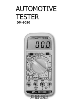
This tester is designed to test or measure AC voltage, DC
voltage, DC current, AC current, resistance, diodes, continu-
ity, frequency, duty cycle, pulse width, rpm and temperature.
Please take the time to read these operating instructions thor-
oughly and completely. Failure to follow these instructions may
result in electrical shock, instrument damage and/or damage
to the equipment under test. Always use extreme caution
when working on or around electrically operated equipment.
SAFETY PRECAUTIONS/ WARNINGS
Do not operate this tester before reading this manual in its
entirety.The following guidelines must be followed to avoid acci-
dents that can result in electric shock or personal injury.
Pay close attention to WARNINGS stamped on the front
and rear of the tester’s case. These warnings, as well as all
warnings and precautions used through out this manual, must
be followed to avoid electric shock and/or personal injury.
The RESPONSIBLE PARTY shall be made aware that, if the
equipment is used in a manner not specified by the manu-
facturer, the protection provided by the equipment may be
impaired.
Before using any of the functions on this tester, verify its
proper operation on a known similar function source where
the unit value is also known.Take corrective action based on
the indicated results.
To prevent electrical shock and/or damage to the tester or the
equipment under test, observe the following safety precautions:
DO NOT apply more than the rated voltage, as marked on
the tester, between terminals or between any terminal and
earth ground.
Use caution when working above 30V AC rms, 42 V peak, or
60 V DC. Such voltages pose a shock hazard.
To avoid false readings that could lead to possible electric
shock or personal injury, replace the batteries as soon as the
low battery indicator displays.
2
E
Always inspect the tester, test leads and any other acces-
sories for damage prior to every use.If any damage is found,
do not use tester until repairs are done.
Always consider electrical and electronic equipment to be ener-
gized (live). Never assume any equipment is de-energized.
Do not connect probes to any available (unused) terminal while
the meter is connected to a hazardous live circuit.
Never ground yourself when taking electrical measurements.
Isolate yourself from ground by using dry rubber insulating
mats to cover all exposed/grounded metal. Stand on rubber
mats and wear dry clothing.
Never take resistance measurements on energized (live)
electrical or electronic equipment.
Use one hand, instead of two, whenever possible to take
measurements.If two hands must be used, use extreme cau-
tion not to contact any energized conductors with your hands.
Be certain test leads are dry and clean.
Do not hold the tester when taking measurements. Place the
tester on a clean, insulating surface prior to taking any meas-
urement.
Don't become part of the circuit.Think safety. Act safely.
If working on a vehicle, take the following added precautions:
Only work on vehicle in a well ventilated area.
Always wear safety eye protection.
Avoid moving fan blades or any potentially moving parts.
Avoid hot engine parts.
Put transmission in "park" (automatic transmission vehicles) or
"neutral" (manual transmission vehicles).Set the parking brake.
Turn the ignition "off" before connecting or disconnecting any
testing equipment.
Put blocks on drive wheels.
Avoid wearing loose clothing or jewelry when working on a
vehicle.
Read your vehicle's service manual and follow it's safety pro-
cedures.
SPECIFICATIONS
GENERAL SPECIFICATIONS AND FEATURES
3-3/4 digit LCD display (maximum reading of 4000)
Range Control: Auto Range
Automatic negative (-) polarity indication
3
E
Automatic zero adjustment
Over range indicator (except 15 A function).Displays "OL" on
LCD
Low battery indicator. Displays battery symbol on LCD
Automatic power shut off (after 10 idle minutes)
Pollution Degree 2
Measuring circuit category II
Operating environment:
Temperature - 32° to 104° F. (0° C to 40° C)
Humidity - Less than 80% relative humidity (non-condensing)
Altitude - up to 6562 ft (2000 meters)
Storage environment:
Temperature - 4° to 140° F (- 20° to 60° C)
Humidity - Less than 90% relative humidity (non-condensing)
Power Supply:Two 1.5V AA batteries
Fuse: 0.500A/250V 5X20 mm (Radio Shack, GMA/270
series; #270-1047) fuse
Dimensions:
Height - 6.81 in. (173 mm)
Width - 6.57 in. (167 mm) (includes test lead clips)
Depth - 1.69 in. (43 mm)
Weight (including batteries): approximately 9.1 oz (260 g)
ELECTRICAL SPECIFICATIONS
DC VOLTS
4
E
Range Resolution Accuracy Overload Protection
400mV 100µV 250V DC RMS
4V 1mV
±(0.8% of
40V 10mV
reading
400V
+ 5 digits)
600V DC/AC RMS
600V
1V
±(0.8% of
reading
+ 5 digits)
Input impedance: 10M for all ranges.
AC VOLTS
RESISTANCE (OHMS)
DC CURRENT (AMPS)
5
E
Range Resolution Accuracy Overload Protection
40mA 10µA
±(1.5% of 0.5A/250V fast fuse
reading (Input Voltage
400mA 100µA
+ 5 digits) Drop: <
0.2V.
±(2.5% of
Unfused; 15sec maximum
*15A 10mA reading
Input Voltage Drop: <
0.2V.
+ 5 digits)
*A waiting period of at least 15 minutes is necessary between
every 15 second testing period.
Range Resolution Accuracy Overload Protection
400 0.1
4k 1
±(1.0% of
40k 10
reading
400k 100
+ 5 digits)
250V DC/AC
4M ±(2.0% of
40M
10k
reading
+ 5 digits)
Range Resolution Accuracy Overload Protection
400mV 100µV ±(1.2% of 250V DC RMS
reading
+8 digits)
4V 1mV
±(0.8% of
40V 10mV
reading
400V
+ 8 digits)
600V DC/AC RMS
600V
1V
±(1.2% of
reading
+ 8 digits)
Input impedance: 10M for all ranges.
Frequency response: 50 - 400Hz
AC CURRENT (AMPS)
DIODE/CONTINUITY TESTS
TEMPERATURE
FREQUENCY
6
E
Function Range Resolution Description Note
Diode Test 2V 1mV Test Current:
1±0.6mA
Test Voltage:
Overload
Approx. 2.8V
Protection:
Continuity 400 0.1 Approx. 120 or
250V DC or
Test less, buzzer
AC RMS
(beeper) will
sound
Range Resolution Accuracy Overload Protection
40mA 10µA ±(2.0% of
0.5A/250V fast fuse
400mA 100µA reading
+ 5 digits)
Input Voltage Drop: <0.2V.
Frequency response: 50 - 400Hz
Range Accuracy Overload Protection
32°F to 104°F ±5°F/±3°C
(0°C to 40°C)
-58°F to 392°F ±1.5%/±5°F
(-50°C to 200°C) (±1.5%/±3°C) 0.5A/250V fast fuse
392°F to 752°F ±2%/±5°F
(200°C to 400°C) (±2%/±3°C)
WARNING
To avoid fire and/or electrical shock hazards, DO NOT con-
nect the thermocouples to circuits greater than 30 Vrms, 42.4
Vpk or 60 Vdc.
Range Resolution Accuracy Overload Protection
9.999Hz- 0.001Hz ±(0.1% of
2MHz reading 250V DC or AC RMS
+ 5 digits)
Sensitivity: <100kHz: 2V RMS; >100kHz: 5V RMS
DUTY CYCLE/PULSE WIDTH/DWELL
RPM
7
E
Function Range Accuracy Overload Protection
Duty Cycle 0.1 to ±(2.0% of
99.9% reading
+ 5 digits)
Pulse Width 1 to 999 ±(3.0% of 0.5A/250V fast fuse
ms positive reading
±2 ms)
Dwell Angle 1-12 ±(2.0% of
cylinders reading
+ 5 digits)
Range Resolution Accuracy Overload Protection
0-10000 1RPM ±(2.0% of
RPM reading 0.5A/250V fast fuse
+ 5 digits)
Frequency response: 50 - 400Hz
WARNING
Risk of Explosion. This equipment has internal arcing and
sparking parts, which should not be exposed to flammable
vapors. This equipment is only suitable for installation in a
garage having sufficient air circulation to be considered a
non-hazardous location.
WARNING
Ignition coils produce a very high voltage.To reduce the risks
of electric shock when conducting RPM tests, DO NOT touch
the uninsulated ends of the test probes, the ignition coil, or
the coil terminals when the engine is running.
CONTROLS AND INDICATORS
1. DCV Function: Measures DC
volts. Auto-ranging from 0 to
600 volts (10 Mimpedance)
2. ACV Function: Measures AC
volts. Auto-ranging from 0 to
600 volts (10 Mimpedance)
3. Press SEL button (see item
19) to select desired function:
Resistance Function :
Measures resistance.Auto
ranging from 0 to 40M
(40,000,000).
Continuity Function :
Tests for continuity be-
tween two points.
Diode Function : For
testing diodes.
4. Frequency Function. Measures frequency. One range:
9.999Hz to 2MHz.
5. Pulse Width Function: Measures the length of time (in mil-
liseconds) that a solenoid or actuator is energized (“ON”
time) during a one-cycle time period. One range: 1 to 999
ms.
6. Duty Cycle Function Measures the percentage of time
that a solenoid or actuator is energized (“ON” time) during a
one-cycle time period. One range: 0.1 to 99.9%.
7. Temperature Function (Celcius): Measures temperature in
°C. Auto-ranging from -50°C to +400°C. (Optional “K-Type”
thermocouple required).
8. Temperature Function (Fahrenheit): Measures tempera-
ture in °F. Auto-ranging from -58°F to +752°F. (Optional “K-
Type” thermocouple required).
9. Press SEL button (see item 19) to select desired function:
ACmA Function: Measures AC current in milliamps.
One range: 0 to 400 milliamps.
DCmA Function: Measures DC current in milliamps.
One range: 0 to 400 milliamps.
10. 15A Function: Measures DC current. One range: 15Amps
(DC from 0 to 15 amperes). Unfused.
11. Clamp Current Function : Measures AC/DC cur-
rent; optional Clamp adapter required.
12. DIS RPM Function: Measures RPM on vehicles with
Distributorless Ignition Systems (DIS) using an optional induc-
tive pickup. One range: 0 to 10,000 rpm.
8
E
27
19
20
1
2
3
4
5
6
7
8
2324172526
9
10
11
12
13
18
14
15
16
21
22
13. CON (Conventional) RPM Function: Measures RPM on
vehicles with conventional ignition systems using an optional
inductive pickup. One range: 0-10,000 rpm.
14. COP RPM Function: Measures RPM on vehicles with “Coil
On Plug” ignition systems. One range: 0 to 10,000 rpm.
15. RPM (Tach) Function: Measures RPM. One range: 0 to
10,000 rpm.
16. Dwell Angle Function : Measures dwell angle of break-
er points.
17. OFF Function: Turns unit “off when function is selected.
18. Function/Range Selector Switch: Selects desired function
or range.
19. Data HOLD Button: Turns the Data Hold function “on” and
“off” (see “Auxiliary Functions” on page 17 for details).
20. MAX/MIN Record Function: Turns the Maximum
Value/Minimum Value Record Mode “on” and “off” (see
“Auxiliary Functions” on page 17 for details).
21. SEL (Select) Button: Selects the desired function when the
Function/Range Selector Switch (item 18) is set to the
Resistance/Continuity/Diode position (item 3), ACmA/DCmA
position (item 9) or Clamp Current Position (item 11).
22. CYL (Cylinder) Button: Selects the number of cylinders for
the vehicle under test when the Function/Range Selector
Switch (item 18) is set to the RPM (Tach) function (item 15)
or Dwell Angle function (item 16).
23. Volts, OHMS, DIODE, CONTINUITY and FREQUENCY
Input Jack.
24. COM Input Jack: Common Input Jack.
25. 15A Input Jack. For red test lead probe connection when
measuring high DC current (up to 15 amps only).
26. DWELL ANGLE, MS °C, °F, BAT, ACmA/DCmA, CLAMP
CURRENT, RPM and COP Input Jack.
27. Liquid Crystal Display (LCD): Displays results of tests or
measurements.
Preparation and Caution Before Use
Inspect the Digital Automotive Tester for damage to the case.
Do not use if cracked, distorted, excessively dirty or any
abnormal condition exists.
Inspect the test leads for damage. Check for cracked insula-
tion, broken or damaged probes, loose or bent probe pins.Do
not use if any abnormal condition exists.
Set the Function/Range Selector Switch to the proper range
BEFORE taking measurements. If the range/function must
9
E
be switched during a test, ALWAYS remove the test leads
from the circuit being measured before switching settings.
To avoid possible electric shock, instrument damage, and/or
equipment damage when taking voltage or current measure-
ments, DO NOT exceed the maximum value of the selected
range.
If the tester is used near high noise Radio Frequency (RF)
generating equipment (spark plug wires, ignition coils or
alternator), the display may become unstable or indicate large
errors. If you obtain erratic readings during use, isolate the
tester as far away as possible from these components.
TESTING PROCEDURES
A. AC/DC VOLTAGE MEASUREMENT
1. Plug the BLACK test lead into "COM" jack of the tester;plug
the RED test lead into the "V" jack.
NOTE: If alligator clip adapters (not included with tester) are to
be used on the test leads, use suitable rated and UL certified
alligator clips.
2. Set the tester’s Function/Range Selector Switch to the
appropriate DCV or ACV position as desired (see
Controls and Indicators, Items 1 and 2).
3. Place the RED test lead onto the positive (+) side of the item
being tested and the BLACK test lead onto the negative (-)
(across the source/load) side of the item.BE CAREFUL not to
touch any energized conductors with any part of your body.
4. Read the results on the display.
10
E
WARNING
To avoid possible electric shock, instrument damage
and/or equipment damage, DO NOT attempt to measure
voltages ABOVE 600V AC/DC or take measurements if
the voltage is unknown. 600V AC/DC between the COM
and V jacks is the maximum voltage that this instrument
is designed to measure. The "COM" terminal potential
should not exceed 300V AC/DC measured to ground.
B. RESISTANCE MEASUREMENT
(OHMS)
1. Plug the RED test lead into the "
" jack of the tester; plug
the BLACK test lead into the "COM" jack.
2. Set the tester’s Function/Range Selector Switch to the
position (see Controls and Indicators, Item 3).
3. Press the SEL button, as necessary, until the (AUTO) icon
is shown on the display.
NOTE: To obtain accurate readings, disconnect at least one
side of the item under test from the circuit or circuit board before
measuring resistance.
4. Place the RED test lead onto one side of the item being test-
ed and the BLACK test lead onto the other side of the item.
(Polarity does not matter when checking resistance).
5. Read the results on the display.
C. DIODE TEST
NOTE: A diode is a semiconductor device that lets current flow in
one direction only. If the diode to be tested is part of a circuit
(with other electronic components), you must isolate it from the
other components by disconnecting at least one side of it from
the circuit before testing. A good diode will show a low voltage
drop across its junction (0.5-0.8 volts for a silicon diode or about
0.3V for a germanium diode) when the leads are connected in
one polarity and a very high resistance (or open circuit) when
the leads are reversed (connected in the opposite polarity).
1. Plug the RED test lead into the jack of the tester; plug
the BLACK test lead into the "COM" jack.
2. Set the tester’s Function/Range Selector Switch to the
position (see Controls and Indicators, Item 3).
11
E
WARNING
To avoid electrical shock and/or damage to the multimeter,
ensure the power is removed from the circuit before any
DIODE testing procedure is conducted.Test diodes on de-
energized (dead) circuits only, never on live circuits.
WARNING
Resistance measurements must be made on "de-ener-
gized" (dead) circuits ONLY. Impressing a voltage across
the multimeter's terminals while set to any resistance
range may result in electric shock, instrument damage
and/or damage to equipment under test. MAKE SURE
equipment is completely de-energized before taking any
resistance measurements.
3. Press the SEL button, as necessary, until the icon is
shown on the display.
4. Place the RED test lead onto one side of the diode being
tested and the BLACK test lead onto the other side.
5. Read the results on the display.
6. Reverse the test leads and again read the results on the dis-
play. Compare the two readings. One reading should indi-
cate a voltage drop value; the other reading should indicate
an overrange (OL) condition.
See note above
.
D. CONTINUITY TEST
1. Plug the RED test lead into the jack of the tester; plug
the BLACK test lead into the "COM" jack.
2. Set the tester’s Function/Range Selector Switch to the
position (see Controls and Indicators, Item 3).
3. Press the SEL button, as necessary, until the icon is
shown on the display.
4. Place the RED Test Lead to one end of the wire or device
being tested for continuity and the BLACK Test Lead to the
opposite end.
5. Listen to the sound of the beeper and confirm the results by
reading the display.
NOTE: The beeper will sound only if the continuity of the item
under test (resistance between the two test leads) measures
less than 120 ohms.
E. FREQUENCY MEASUREMENT
Frequency is the number of times that an event repeats itself during
a one-second time period. Frequency is measured in Hertz (Hz).
1. Plug the RED test lead into the “Hz” jack of the tester; plug
the BLACK test lead into the "COM" jack.
2. Set the tester’s Function/Range Selector Switch to the Hz
position (see Controls and Indicators, Item 4).
3. Place the RED test lead onto the signal output wire of the
sensor or circuit under test and the BLACK test lead onto a
good chassis ground (consult the wiring diagram in the vehi-
cle’s Service Manual for proper connections).
4. Read the results on the display.
12
E
WARNING
To avoid electric shock, shut off the power to the test arti-
cle before testing it for continuity.
F. PULSE WIDTH MEASUREMENT
Pulse Width is the length of time that a solenoid or actuator is
energized (“ON” time) during a one-cycle time period. Pulse
Width is measured in milliseconds (ms).
1. Plug the RED test lead into the “ms jack of the tester; plug
the BLACK test lead into the "COM" jack.
2. Set the tester’s Function/Range Selector Switch to the ms
position (see Controls and Indicators, Item 5).
3. Place the RED test lead onto the signal output wire of the
sensor or circuit under test and the BLACK test lead onto a
good chassis ground (consult the wiring diagram in the
vehicle’s Service Manual for proper connections).
4. Read the results on the display.
G. DUTY CYCLE MEASUREMENT
Duty Cycle is the percentage of time that a solenoid or actuator
is energized (“ON” time) during a one-cycle time period. Duty
Cycle is measured in percent (%).
1. Plug the RED test lead into the jack of the tester;
plug the BLACK test lead into the "COM" jack.
2. Set the tester’s Function/Range Selector Switch to the
DUTY% position (see Controls and Indicators, Item 6).
3. Place the RED test lead onto the signal wire of the sensor
or circuit under test and the BLACK test lead onto a good
chassis ground (consult the wiring diagram in the vehicle’s
Service Manual for proper connections).
4. Read the results on the display.
H. TEMPERATURE MEASUREMENT
NOTE: Temperature measurement requires use of an optional
“K-type” thermocouple.
1. Plug the Positive (+) test lead of the “K-type” thermocouple
into the °C / °F jack of the tester; plug the Negative (-) test
lead into the “15A” jack.
2. Set the tester’s Function/Range Selector Switch to the °C or °F
position, as desired (see Controls and Indicators, Items 7 and 8).
3. Read the results on the display.
13
WARNING
To avoid fire and/or electrical shock hazards, DO NOT con-
nect the thermocouples to circuits greater than 30 Vrms, 42.4
Vpk or 60 Vdc.
I. AC/DC CURRENT MEASUREMENT (AMPS)
1. Plug the RED test lead into the or the "15A" jack of
the tester, as applicable; plug the BLACK test lead to the
"COM" jack.
2. Set the tester’s Function/Range Selector Switch to the
appropriate Amps range position as desired (see Controls
and Indicators, Items 9 and 10).
Use the SEL button (see Controls and Indicators, item
20) to select DC Amps or AC Amps, as desired.
To measure from 0 to 400mA, set the Selector Switch to
.
To measure from 400mA to 15 Amps DC, set the
Selector Switch to the "15A" position.
3. Disconnect the battery, or shut off the power to the circuit
being tested.
NOTE: To measure current on a particular circuit, you must open
up the circuit and connect the test leads in series with the circuit
before a reading can be obtained.
4. Disconnect one end of the wire or device, from the circuit
where current will be measured.
5. Place the RED test lead on the disconnected wire and place
the BLACK test lead at the location from which the wire was
disconnected (series connection).
6. Reconnect the battery, or apply power to the circuit being
tested.
7. Read the results on the display.
CAUTION: After the test is completed, shut the power off to
the circuit before removing the test leads and before recon-
necting any disconnected wires or devices.
NOTE: If the reading obtained is a negative number, reverse the
test leads.
14
WARNING
To prevent electrical shock when performing current
measurements, follow all steps as indicated below DO
NOT skip any steps or take any short cuts.
The 15A range is not fused. To avoid current hazard
and/or damage to the tester, DO NOT try to take meas-
urements on circuits that have more than 15 amps. DO
NOT take more than 10 seconds to take the reading. A
waiting period of AT LEAST 15 MINUTES is necessary
between every 15 second testing period.
J. CLAMP CURRENT MEASUREMENT
NOTE: Clamp current measurement requires use of an optional
Clamp adapter. The optional Clamp adapter has not been eval-
uated by UL.
1. Plug the RED test lead from the Clamp adapter to the
jack of the tester; plug the BLACK test lead into the "COM"
jack.
2. Set the tester’s Function/Range Selector Switch to the
position (see Controls and Indicators, Item 11).
3. Clamp the Clamp adapter around the wire or cable from the
source or load under measurement.
4. Read the results on the display.
K. COP RPM AND RPM (TACH) MEASUREMENT
1. Plug the RED test lead into the "RPM." jack of the tester;
plug the BLACK test lead into the "COM" jack.
2. Place the RED test lead onto the “Tachometer Signal port”
of the vehicle’s ignition system, or onto the negative (-) side
of the ignition coil. Place the BLACK test lead onto a good
chassis ground or the negative (-) terminal of the battery.
NOTE: If your vehicle is equipped with a COP (Coil On
Plug) system and you are using the setting, make the
RED test lead connection to the negative (-) side of one of
the ignition coils.
3. Set the tester’s Function/Range Selector Switch to the
or position, as appropriate (see Controls and
Indicators, Items 14 and 15).
15
WARNING
Risk of Explosion. This equipment has internal arcing and
sparking parts, which should not be exposed to flammable
vapors. This equipment is only suitable for installation in a
garage having sufficient air circulation to be considered a non-
hazardous location.
WARNING
Ignition coils produce a very high voltage. To reduce the risk of
electric shock when conducting RPM tests, DO NOT touch the
uninsulated ends of the test probes, the ignition coil, or the coil
terminals when the engine is running.
4. Press the CYL button, as necessary, until the correct num-
ber of cylinders for the vehicle under test is shown on the
display.
NOTE: Cylinder selection is not applicable to COP (Coil On
Plug) systems.
5. Start the engine and read the results on the display.
L. CON AND DIS RPM MEASUREMENT
NOTE: CON or DIS rpm measurement requires use of an
inductive pickup.
1. Turn the ignition off. DO NOT CONNECT THE INDUCTIVE
PICKUP WITH THE ENGINE RUNNING OR WITH THE
IGNITION ON.
2. Clamp the inductive pickup clamp around the No. 1 spark
plug wire.
3. Plug the RED inductive pickup lead into the "RPM." jack of
the tester; plug the BLACK inductive pickup lead into the
"COM" jack.
4. Set the tester’s Function/Range Selector Switch to the
or position, as appropriate (see Controls and
Indicators, Item 12 and 13).
NOTE: Cylinder selection is not required when using the
inductive pickup.
5. Start the engine and read the results on the display.
16
WARNING
Risk of Explosion. This equipment has internal arcing and
sparking parts, which should not be exposed to flammable
vapors. This equipment is only suitable for installation in a
garage having sufficient air circulation to be considered a non-
hazardous location.
WARNING
Ignition coils produce a very high voltage. To reduce the risk
of electric shock when conducting RPM tests, DO NOT touch
the inductive pickup, the ignition coil, or the coil terminals
when the engine is running.
M. DWELL ANGLE MEASUREMENT
NOTE: Turn the vehicle’s engine “off BEFORE connecting the
multimeter for DWELL ANGLE MEASUREMENT.
1. Plug the RED test lead into the jack of the tester; plug
the BLACK test lead into the "COM" jack.
2. Place the RED test lead to the “BREAKER POINTS” or “-”
terminal of the ignition coil and the BLACK test lead to
“GROUND” or the “-” terminal of the battery.
3. Set the tester’s Function/Range Selector Switch to the
position (see Controls and Indicators, Item 16).
4. Press the CYL button, as necessary, until the correct num-
ber of cylinders for the vehicle under test is shown on the
display.
5. Start the engine and read the results on the display.
AUXILIARY FUNCTIONS
A. DATA HOLD FUNCTION
The data HOLD function lets you “lock” the currently displayed
value into the display.The value remains on the display until the
function is turned “off.
1. With the desired value shown on the display, press and hold
the HOLD button for approximately two seconds, until the
HOLD icon shows on the display. The current value is now
“locked” in the display.
2. Press the HOLD button again to turn the function “off. The
HOLD icon will disappear, and the value will no longer be
“locked” in the display.
NOTE: The data HOLD function is not available for the DIODE
TEST, CONTINUITY TEST or PULSE WIDTH MEASUREMENT.
B. MINIMUM/MAXIMUM VALUE FUNCTION
The MAX/MIN function records and saves the maximum and/or
minimum readings that were achieved during a test.
1. Prepare the tester to perform the desired test as follows
(refer to the detailed TESTING PROCEDURES starting on
page 10 for the specific connections and settings for the test
you wish to perform):
Plug the test leads into the appropriate jacks.
Set the tester’s Function/Range Selector Switch to the
appropriate position.
Connect the test leads to the item to be tested.
17
2. To record Maximum/Minimum readings, press and release
the MAX/MIN button to place the tester in MAX/MIN mode.
The MAX icon will be visible on the display. Perform the
desired test; the
maximum
reading achieved during the test
will be recorded and saved in the tester’s memory.
3. Press the MAX/MIN button again.The MIN icon will be visi-
ble on the display. Perform the desired test; the minimum
reading achieved during the test will be recorded and saved
in the tester’s memory.
To scroll between MAX and MIN readings that are stored
in the tester’s memory, rapidly press and release the
MAX/MIN button.
4. To exit MAX/MIN mode press and hold MAX/MIN button for
approximately 2-3 seconds, or until MAX/MIN icons disap-
pear from the display.
The tester will save the MAX/MIN readings in memory until
the MAX/MIN mode is exited or the tester is turned off.
NOTE: MAX/MIN functions is not applicable to the Diode,
Continuity or Frequency Functions.
BATTERY AND FUSE REPLACEMENT
1. Turn the Digital Automotive Tester “OFF and remove the
test leads.
2. Replace the fuse or batteries as necessary:
For battery replacement:
Remove one screw from the battery compartment cover.
Use your finger or a small coin to remove the cover.
Remove the batteries and replace them with two AA (1-
1/2 Volt alkaline batteries.
For fuse replacement:
Remove the three screws (you must remove the meter
stand to remove the third screw) on the back of the
meter and separate the case.Remove the fuse from the
fuse holder and replace with a 0.500A/250V - UL Listed
Bussmann, GMA Type (Radio Shack GMA/270
Series: #270-1047) fuse.
NOTE: Use a 0.500A/250V, 5x20mm type fuse ONLY -
Bussmann, GMA Type (Radio Shack #270-1047 or similar).
Using an incorrect fuse may result in serious injury and/or damage
to the unit.
3. Reassemble the cover/case and secure with the screws.
18
MAINTENANCE
1. No periodic maintenance is required other than the replace-
ment of the battery, the fuse, and visual inspection of the
meter.
2. Keep the tester clean and dry.DO NOT use solvent to clean,
use a damp (not wet) cloth and fully dry after cleaning.
3. The only replaceable parts are the 1.5 AA batteries,
0.500A/250V fuse (see page 18 for battery and fuse
replacement) and the Test Leads (for Test Leads call serv-
ice department).
19
  • Page 1 1
  • Page 2 2
  • Page 3 3
  • Page 4 4
  • Page 5 5
  • Page 6 6
  • Page 7 7
  • Page 8 8
  • Page 9 9
  • Page 10 10
  • Page 11 11
  • Page 12 12
  • Page 13 13
  • Page 14 14
  • Page 15 15
  • Page 16 16
  • Page 17 17
  • Page 18 18
  • Page 19 19
  • Page 20 20
  • Page 21 21
  • Page 22 22
  • Page 23 23
  • Page 24 24

Innova 3340 Owner's manual

Category
Multimeters
Type
Owner's manual

Innova 3340 is a versatile automotive electrical tester that measures AC/DC voltage, DC current, AC current, resistance, temperature, frequency, duty cycle, pulse width, and RPM. It performs diode tests and continuity checks as well. With auto-ranging and auto-polarity features, the Innova 3340 simplifies automotive electrical diagnostics, making it suitable for both professional technicians and DIYers.

Ask a question and I''ll find the answer in the document

Finding information in a document is now easier with AI