Page is loading ...

EASYLIFE
S U S T A I N A B L E C O M F O R T
®
MW-L000541-2
en
User Manual
Solar tank
UNO
BSL 150...400
BESL 200...400

Dear Customer,
Thank you very much for buying this appliance.
Please read through the manual carefully before using the product, and keep it in a safe place for later reference. In order to
ensure continued safe and efficient operation we recommend that the product is serviced regularly. Our service and customer
service organisation can assist with this.
We hope you enjoy years of problem-free operation with the product.

Contents
1 Safety . . . . . . . . . . . . . . . . . . . . . . . . . . . . . . . . . . . . . . . . . . . . . . . . . . . . . . . . . . . . . . . . . . . . . . . . . . . . . . . . . . . . . . . . . . . . 4
1.1 Safety . . . . . . . . . . . . . . . . . . . . . . . . . . . . . . . . . . . . . . . . . . . . . . . . . . . . . . . . . . . . . . . . . . . . . . . . . . . . . . . . . . . . . . . 4
1.2 Recommendations . . . . . . . . . . . . . . . . . . . . . . . . . . . . . . . . . . . . . . . . . . . . . . . . . . . . . . . . . . . . . . . . . . . . . . . . . . . . . 5
1.3 Liabilities . . . . . . . . . . . . . . . . . . . . . . . . . . . . . . . . . . . . . . . . . . . . . . . . . . . . . . . . . . . . . . . . . . . . . . . . . . . . . . . . . . . . . 6
2 About this manual . . . . . . . . . . . . . . . . . . . . . . . . . . . . . . . . . . . . . . . . . . . . . . . . . . . . . . . . . . . . . . . . . . . . . . . . . . . . . . . . . . . 7
2.1 Symbols used . . . . . . . . . . . . . . . . . . . . . . . . . . . . . . . . . . . . . . . . . . . . . . . . . . . . . . . . . . . . . . . . . . . . . . . . . . . . . . . . . 7
2.1.1 Symbols used in the manual . . . . . . . . . . . . . . . . . . . . . . . . . . . . . . . . . . . . . . . . . . . . . . . . . . . . . . . . . . . . . . 7
2.1.2 Symbols used on the equipment . . . . . . . . . . . . . . . . . . . . . . . . . . . . . . . . . . . . . . . . . . . . . . . . . . . . . . . . . . . 7
3 Description of the product . . . . . . . . . . . . . . . . . . . . . . . . . . . . . . . . . . . . . . . . . . . . . . . . . . . . . . . . . . . . . . . . . . . . . . . . . . . . . 8
3.1 Homologations . . . . . . . . . . . . . . . . . . . . . . . . . . . . . . . . . . . . . . . . . . . . . . . . . . . . . . . . . . . . . . . . . . . . . . . . . . . . . . . . 8
3.1.1 Certifications . . . . . . . . . . . . . . . . . . . . . . . . . . . . . . . . . . . . . . . . . . . . . . . . . . . . . . . . . . . . . . . . . . . . . . . . . . 8
3.2 Solar domestic hot water tank . . . . . . . . . . . . . . . . . . . . . . . . . . . . . . . . . . . . . . . . . . . . . . . . . . . . . . . . . . . . . . . . . . . . .8
3.3 Control panel description . . . . . . . . . . . . . . . . . . . . . . . . . . . . . . . . . . . . . . . . . . . . . . . . . . . . . . . . . . . . . . . . . . . . . . . 10
3.3.1 Description of the keys . . . . . . . . . . . . . . . . . . . . . . . . . . . . . . . . . . . . . . . . . . . . . . . . . . . . . . . . . . . . . . . . . 10
3.3.2 Description of the display . . . . . . . . . . . . . . . . . . . . . . . . . . . . . . . . . . . . . . . . . . . . . . . . . . . . . . . . . . . . . . . .10
4 Operation . . . . . . . . . . . . . . . . . . . . . . . . . . . . . . . . . . . . . . . . . . . . . . . . . . . . . . . . . . . . . . . . . . . . . . . . . . . . . . . . . . . . . . . . .12
4.1 Displaying the measured values . . . . . . . . . . . . . . . . . . . . . . . . . . . . . . . . . . . . . . . . . . . . . . . . . . . . . . . . . . . . . . . . . . 12
4.1.1 Resetting the values to zero . . . . . . . . . . . . . . . . . . . . . . . . . . . . . . . . . . . . . . . . . . . . . . . . . . . . . . . . . . . . . 12
4.2 User settings . . . . . . . . . . . . . . . . . . . . . . . . . . . . . . . . . . . . . . . . . . . . . . . . . . . . . . . . . . . . . . . . . . . . . . . . . . . . . . . . . 12
4.2.1 Setting the time . . . . . . . . . . . . . . . . . . . . . . . . . . . . . . . . . . . . . . . . . . . . . . . . . . . . . . . . . . . . . . . . . . . . . . . 12
4.2.2 Forcing the back-up . . . . . . . . . . . . . . . . . . . . . . . . . . . . . . . . . . . . . . . . . . . . . . . . . . . . . . . . . . . . . . . . . . . .13
4.2.3 Modifying the back-up authorisations . . . . . . . . . . . . . . . . . . . . . . . . . . . . . . . . . . . . . . . . . . . . . . . . . . . . . . 13
4.2.4 In the event of prolonged absence . . . . . . . . . . . . . . . . . . . . . . . . . . . . . . . . . . . . . . . . . . . . . . . . . . . . . . . . 13
4.3 Setting the tank outlet temperature . . . . . . . . . . . . . . . . . . . . . . . . . . . . . . . . . . . . . . . . . . . . . . . . . . . . . . . . . . . . . . . .14
4.3.1 Programming and adjusting the electrical back-up . . . . . . . . . . . . . . . . . . . . . . . . . . . . . . . . . . . . . . . . . . . . 14
4.3.2 Setting the thermostatic mixing valve . . . . . . . . . . . . . . . . . . . . . . . . . . . . . . . . . . . . . . . . . . . . . . . . . . . . . . 14
4.4 Starting and stopping the control system . . . . . . . . . . . . . . . . . . . . . . . . . . . . . . . . . . . . . . . . . . . . . . . . . . . . . . . . . . . 14
5 Maintenance . . . . . . . . . . . . . . . . . . . . . . . . . . . . . . . . . . . . . . . . . . . . . . . . . . . . . . . . . . . . . . . . . . . . . . . . . . . . . . . . . . . . . . 15
5.1 General instructions . . . . . . . . . . . . . . . . . . . . . . . . . . . . . . . . . . . . . . . . . . . . . . . . . . . . . . . . . . . . . . . . . . . . . . . . . . . 15
5.2 Safety valve or safety unit . . . . . . . . . . . . . . . . . . . . . . . . . . . . . . . . . . . . . . . . . . . . . . . . . . . . . . . . . . . . . . . . . . . . . . .15
5.3 Cleaning the casing . . . . . . . . . . . . . . . . . . . . . . . . . . . . . . . . . . . . . . . . . . . . . . . . . . . . . . . . . . . . . . . . . . . . . . . . . . . 15
5.4 Checking the magnesium anode . . . . . . . . . . . . . . . . . . . . . . . . . . . . . . . . . . . . . . . . . . . . . . . . . . . . . . . . . . . . . . . . . 15
6 Troubleshooting . . . . . . . . . . . . . . . . . . . . . . . . . . . . . . . . . . . . . . . . . . . . . . . . . . . . . . . . . . . . . . . . . . . . . . . . . . . . . . . . . . . .16
6.1 Fault finding . . . . . . . . . . . . . . . . . . . . . . . . . . . . . . . . . . . . . . . . . . . . . . . . . . . . . . . . . . . . . . . . . . . . . . . . . . . . . . . . . .16
7 Technical specifications . . . . . . . . . . . . . . . . . . . . . . . . . . . . . . . . . . . . . . . . . . . . . . . . . . . . . . . . . . . . . . . . . . . . . . . . . . . . . 17
7.1 Solar domestic hot water tank . . . . . . . . . . . . . . . . . . . . . . . . . . . . . . . . . . . . . . . . . . . . . . . . . . . . . . . . . . . . . . . . . . . .17
7.2 Composition of the NF CESI solar system packages (for France) . . . . . . . . . . . . . . . . . . . . . . . . . . . . . . . . . . . . . . . . 18
8 Warranty . . . . . . . . . . . . . . . . . . . . . . . . . . . . . . . . . . . . . . . . . . . . . . . . . . . . . . . . . . . . . . . . . . . . . . . . . . . . . . . . . . . . . . . . . 21
8.1 General . . . . . . . . . . . . . . . . . . . . . . . . . . . . . . . . . . . . . . . . . . . . . . . . . . . . . . . . . . . . . . . . . . . . . . . . . . . . . . . . . . . . . 21
8.2 Terms of warranty . . . . . . . . . . . . . . . . . . . . . . . . . . . . . . . . . . . . . . . . . . . . . . . . . . . . . . . . . . . . . . . . . . . . . . . . . . . . . 21
9 Appendix . . . . . . . . . . . . . . . . . . . . . . . . . . . . . . . . . . . . . . . . . . . . . . . . . . . . . . . . . . . . . . . . . . . . . . . . . . . . . . . . . . . . . . . . . 23
9.1 Information on the ecodesign and energy labelling directives . . . . . . . . . . . . . . . . . . . . . . . . . . . . . . . . . . . . . . . . . . . 23
9.1.1 Specific information . . . . . . . . . . . . . . . . . . . . . . . . . . . . . . . . . . . . . . . . . . . . . . . . . . . . . . . . . . . . . . . . . . . . 23
Contents
300028413 - v06 - 03032020 BSL 150...400 — BESL 200...400 3

1 Safety
1.1 Safety
Danger
This appliance can be used by children aged from
8 years and above and persons with reduced
physical, sensory or mental capabilities or lack of
experience and knowledge if they have been
given supervision or instruction concerning use of
the appliance in a safe way and understand the
hazards involved. Children shall not play with the
appliance. Cleaning and user maintenance shall
not be made by children without supervision.
Caution
Draining the domestic hot water tank:
1. Shut off the domestic cold water inlet.
2. Open a hot water tap in the installation.
3. Open a valve on the safety unit.
4. When the water stops flowing, the domestic
hot water tank has been drained.
Warning
Pressure limiter device
The pressure limiter device (safety valve or
safety unit) must be regularly operated in order
to remove limescale deposits and ensure that it
is not blocked.
A pressure limiter device must be fitted to a
discharge pipe.
As water may flow out of the discharge pipe, the
pipe must be kept open to the open air, in a
frost-free environment, and at a continuous
downward gradient.
To ascertain the type, specifications and
connection of the pressure limiter device, refer
to the chapter "Connecting the domestic hot
water tank to the drinking water mains" in the
domestic hot water tank Installation and Service
Manual.
Important
The user and installation manuals are also
available on our website.
1 Safety
4 BSL 150...400 — BESL 200...400 300028413 - v06 - 03032020

Caution
A disconnection method must be allowed in the
fixed pipes in accordance with the rules on
installation in force in the country.
Caution
If a power cord comes with the appliance and it
turns out to be damaged, it must be replaced by
the manufacturer, its after sales service or
persons with similar qualifications in order to
obviate any danger.
Warning
Respect the minimum water inlet pressure to
ensure correct operation of the appliance,
referring to the chapter "Technical
Specifications".
Warning
Before any work, switch off the power supply to
the appliance.
1.2 Recommendations
Caution
Do not neglect to service the appliance.
Service the appliance regularly to ensure that it operates correctly.
Danger
Only qualified persons are authorised to assemble, install and
maintain the installation.
Warning
The heating water and the water-propylene-glycol mixture must
not come into contact with the domestic hot water.
The domestic hot water must not circulate through an
exchanger.
Solar installations can be protected against lightning and must
be earthed or connected to an equipotential connection.
To benefit from extended warranty cover, no modifications should be
made to the appliance. Only remove the covers for maintenance and
breakdown repair operations and put the covers back in place once these
operations are complete.
Warning stickers
The instructions and warnings affixed to the appliance must never be
removed or covered and must remain legible during the entire lifespan of
the appliance. Immediately replace damaged or illegible instructions and
warning stickers.
1 Safety
300028413 - v06 - 03032020 BSL 150...400 — BESL 200...400 5

Warning
Never turn the power off to the solar control system even for
extended absences. The control system protects the installation
from overheating when it is operating in the summer.
Warning
Do not modify the control system parameters unless fully
conversant with them.
During extended absences, we recommend lowering the setpoint
temperature in the solar DHW tank to 45 °C. When the user is present, the
setpoint should be set to 60 °C.
1.3
Liabilities
Tab.1
Manufacturer's liability Our products are manufactured in compliance with the requirements of the various Di
rectives applicable. They are therefore delivered with the marking and any docu
ments necessary. In the interests of the quality of our products, we strive constantly to
improve them. We therefore reserve the right to modify the specifications given in this
document.
Our liability as manufacturer may not be invoked in the following cases:
Failure to abide by the instructions on installing the appliance.
Failure to abide by the instructions on using the appliance.
Faulty or insufficient maintenance of the appliance.
Installer's liability The installer is responsible for the installation and initial commissioning of the appliance.
The installer must observe the following instructions:
Read and follow the instructions given in the manuals provided with the appliance.
Install the appliance in compliance with prevailing legislation and standards.
Carry out initial commissioning and any checks necessary.
Explain the installation to the user.
If maintenance is necessary, warn the user of the obligation to check the appliance
and keep it in good working order.
Give all the instruction manuals to the user.
User's liability To guarantee optimum operation of the system, the user must abide by the following in
structions:
Read and follow the instructions given in the manuals provided with the appliance.
Call on a qualified professional to carry out installation and initial commissioning.
Ask your installer to explain your installation to you.
Have the required inspections and maintenance carried out by a qualified installer.
Keep the instruction manuals in good condition close to the appliance.
1 Safety
6 BSL 150...400 — BESL 200...400 300028413 - v06 - 03032020

2 About this manual
2.1 Symbols used
2.1.1 Symbols used in the manual
This manual uses various danger levels to draw attention to special
instructions. We do this to improve user safety, to prevent problems and to
guarantee correct operation of the appliance.
Danger
Risk of dangerous situations that may result in serious personal
injury.
Danger of electric shock
Risk of electric shock.
Warning
Risk of dangerous situations that may result in minor personal
injury.
Caution
Risk of material damage.
Important
Please note: important information.
See
Reference to other manuals or pages in this manual.
2.1.2 Symbols used on the equipment
1 Before installing and commissioning the appliance, carefully read
the instruction manuals provided
2 Dispose of used products in an appropriate recovery and recycling
structure
Fig.1
1
2
MW-6000691-1
2 About this manual
300028413 - v06 - 03032020 BSL 150...400 — BESL 200...400 7

3 Description of the product
3.1 Homologations
3.1.1 Certifications
This product complies with the requirements of European directives and
the following standards:
Pressure Equipment Directive 2014/68/EU
Electromagnetic Compatibility Directive 2014/30/EU
Generic standards: EN 61000-6-3, EN 61000-6-1
Relevant Standard: EN 55014
Low Voltage Directive 2014/35/EU
Generic standard: EN 60335-1
Relevant standard: EN 60335-2-40
Standard DIN 1988 (TWRWI): technical regulations for drinking water
installations
This product conforms to the requirements of European Directive
2009/125/EC on the ecodesign of energy-related products.
In addition to the legal requirements and guidelines, the supplementary
guidelines in this manual must also be followed.
Supplements or subsequent regulations and guidelines that are valid at
the time of installation shall apply to all regulations and guidelines
specified in this manual.
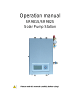
3.2 Solar domestic hot water tank
1 Top inspection hatch
2 Solar control system
3 Safety unit for the solar circuit
4 Solar station
6 Expansion vessel
Important
All components are checked for leaks and tested in the factory.
The control system, pump and electrical back-up are pre-wired.
Fig.2
Fig.3 BSL 150
MW-2001112-1
1
2
4
6
3
3 Description of the product
8 BSL 150...400 — BESL 200...400 300028413 - v06 - 03032020

1 Top inspection hatch
2 Solar control system
3 Safety unit for the solar circuit
4 Solar station
5 Electrical back-up (optional)
6 Expansion vessel
7 Side inspection hatch
Important
All components are checked for leaks and tested in the factory.
The control system, pump and electrical back-up are pre-wired.
1 Top inspection hatch
2 Solar control system
3 Safety unit for the solar circuit
4 Solar station
5 Electrical back-up
6 Expansion vessel
7 Side inspection hatch
Fig.4 BSL 200, BSL 300, BSL 400
MW-2001113-1
2
1
3
4
5
7
6
Fig.5 BESL 200, BESL 300, BESL 400
MW-2001114-1
2
3
4
5
6
1
7
3 Description of the product
300028413 - v06 - 03032020 BSL 150...400 — BESL 200...400 9

3.3 Control panel description
3.3.1 Description of the keys
A
key:
Move the cursor upwards.
Increase the value of the parameter.
B
key:
Access a selected parameter.
Confirm a value modification.
C
key:
Move the cursor downwards.
Reduce the parameter value.
D 3-position switch:
: The back-up may be active in day mode and night mode
0: The back-up is deactivated.
: The back-up is active in night mode only.
3.3.2 Description of the display
System diagrams (System-Screen)
1 Solar collector sensor
2 Solar collectors
3 Solar circulating pump
4 Solar exchanger
5 Solar calorifier
6 Solar sensor
7 Back-up (excluding BSL 150)
8 Domestic hot water sensor – Back-up
Operating indicators
Tab.2
Steady sym
bol
Flashing symbol Status
Solar pump activated.
Back-up activated.
Tank setpoint temperature exceeded.
Cooling function of the collector or
tank activated.
Antifreeze function activated.
Antifreeze function active (running).
Minimum collector temperature excee
ded.
Maximum tank temperature exceeded.
Maximum collector temperature ex
ceeded.
Fig.6
M002759-A
A
B
C
D
Fig.7
M002760-A
1
4 5
2
3
7
8
6
Fig.8
M002761-A
II I
3 Description of the product
10 BSL 150...400 — BESL 200...400 300028413 - v06 - 03032020

Steady sym
bol
Flashing symbol Status
Adjustment parameter.
Modification of settings.
Sensor fault.
+
Forced running of the solar pump.
+
Forced running of the back-up.
LED indicator
A LED
Tab.3
LED mes
sage code
Circulating pump status Description
Continuously
green
The pump relay is
closed.
Control system operating nor
mally.
Green/red
flashing
Initialisation phase.
Manual mode.
The installation is in manual
mode: Set the control system to
automatic mode.
Red flashing Sensor fault.
Maximum tank tem
perature exceeded.
The tank has reached the
setpoint temperature and the
installation is in overheating
safety mode or in cooling
mode.
There is a sensor fault.
Fig.9
M002762-A
A
3 Description of the product
300028413 - v06 - 03032020 BSL 150...400 — BESL 200...400 11

4 Operation
4.1 Displaying the measured values
Scroll through the measured values using the or keys.
Tab.4
Parameter Description Notes
TC Collector temperature Sensor S1.
The value TC shows the temperature in °C measured by the collector sen
sor in real time.
TR Tank temperature (Solar exchang
er - bottom)
Sensor S2.
The value TR shows the temperature in °C measured by the sensor in the
lower zone of the DHW tank in real time.
THR Tank temperature (Back-up) Sensor S3.
The value THR shows the temperature in °C measured by the sensor in the
upper zone of the DHW tank in real time.
PC % Pump speed The value PC % shows the speed of the solar circulating pump (0 - 100 %)
in real time.
tc Self-calibration time The value tc shows the remaining self-calibration phase time in seconds.
RAP Forcing the back-up On: Back-up powered up.
AUTO: Back-up managed by the control system.
See
Chapter Forcing the back-up, page 13
h P1 Operating hour counter for the so
lar pump
Reset to zero possible.
KWh Amount of heat (kWh) The amount of heat received is calculated according to the parameters
entered during start-up (DMAX).
Reset to zero possible.
The values KWhor MWhgive an estimation in kWh or MWh of the total
amount of heat produced by the installation since the control system was
commissioned.
MWh Amount of heat (MWh)
HRE Time
See
Chapter Setting the time, page 12
For more information, see
Forcing the back-up, page 13
Setting the time, page 12
4.1.1
Resetting the values to zero
It is possible to reset the values to zero when the symbol is
displayed.
1. Select a value using the and keys.
2. Press the key for 2 seconds. The value is reset to zero.
Important
To suspend the operation, do not press any keys for 5 seconds.
The control system will automatically return to the value display
mode.
4.2
User settings
4.2.1 Setting the time
1. Select the HRE channel using the and keys.
4 Operation
12 BSL 150...400 — BESL 200...400 300028413 - v06 - 03032020

2. Press the key for 2 seconds.
3. Set the hours with the and keys.
4. Press the key to confirm.
5. Set the minutes with the and keys.
6. Press the key to confirm.
Caution
The controller does not switch between summer and winter time
automatically.
4.2.2
Forcing the back-up
1. Select the RAP channel using the and keys.
2. Press the key for 2 seconds. The symbol flashes.
3. Set the parameter RAP to ON using the key.
Important
The electrical back-up shuts down when the setpoint temperature
is reached.
4.2.3
Modifying the back-up authorisations
1. Toggle the switch to modify the electrical back-up authorisations.
Tab.5
Winter: The back-up is authorised day and night.
0 The back-up is not authorised. No back-up heating.
Summer: The back-up is only authorised at night.
Important
The back-up is deactivated if the solar pump is running.
4.2.4 In the event of prolonged absence
In the event of a prolonged absence, shut down the electrical back-up if
the function is activated and reduce the solar tank setpoint:
1. Set the 3-position switch to 0.
2.
Move to the last display channel (HRE) using the key.
3. Press the key for 5 seconds.
A setting parameter is displayed, with the symbol.
4. Select the parameter SX using the and keys.
5. Briefly press the key.
The symbol flashes, the parameter can be set.
6. Modify the parameter using the and keys.
For example 45 (°C).
7. Press the key to confirm the setting.
Return from prolonged absence
On return from a prolonged absence:
1. Adjust the setpoint for the solar tank SX to its installation value.
2. Re-authorise the back-ups.
3. Set the 3-position switch to winter or summer, according to the
season.
Fig.10
M002763-A
Fig.11
I
M002799-A
4 Operation
300028413 - v06 - 03032020 BSL 150...400 — BESL 200...400 13

4.3 Setting the tank outlet temperature
4.3.1 Programming and adjusting the electrical back-up
The temperature of the water volume heated by the immersion heater is
set by the installer at the start-up of the installation according to the size of
the home.
Using the solar control system, it is possible to adjust the volume of water
heated to 40 °C by the heater in two ways:
Force the continuous heating of the heater for significant unforeseen
needs.
Select winter mode (maximum of 2 hours according to the volume of
domestic hot water required at 40 °C) to offset a lack of sunshine in the
winter. If necessary, the programmed period excluding off-peak hours is
set between 4 pm and 6 pm, i.e. at the end of the day when the solar
contribution is reduced and just before the draw-off period.
For more information, see
Forcing the back-up, page 13
Modifying the back-up authorisations, page 13
4.3.2 Setting the thermostatic mixing valve
28 Domestic cold water inlet
57 Domestic hot water outlet
The mixing valve is set in the factory for a domestic hot water outlet
temperature of 60°C (position 6). To lower this temperature, remove the
top cover and turn the wheel anti-clockwise. In position 1, the outlet
temperature is lowered to 35°C.
Tab.6
Position 1 2 3 4 5 6
Temperature at
the mixing valve
outlet
35°C 40°C 45°C 50°C 55°C 60°C
4.4
Starting and stopping the control system
Caution
If the temperature in the solar collectors is higher than 130 °C, the
control system operates in safety mode. Wait until the evening
before starting-up or cooling down (covering) the solar collectors.
Commissioning is performed by the installer. Once connected to the power
supply, the control system is in automatic mode. To activate the solar
pump, a minimum temperature of 30 °C is required at the collector, and
the difference in temperature compared to the domestic hot water tank
must be 6 °C.
Important
If the particular conditions make it so that it is necessary to adjust
the settings, contact the installer.
Fig.12
C003732-B
57
28
4 Operation
14 BSL 150...400 — BESL 200...400 300028413 - v06 - 03032020

5 Maintenance
5.1 General instructions
Caution
Maintenance operations must be completed by a qualified
installer.
Use only genuine spare parts.
5.2 Safety valve or safety unit
1. The safety valve or unit on the domestic cold water inlet must be
operated at least
once a month in order to ensure that it works
properly and take precautions against possible pressure surges which
would damage the domestic hot water tank.
Warning
Failure to follow this maintenance requirement may lead to the
deterioration of the domestic hot water tank and void its warranty.
5.3 Cleaning the casing
1. Clean the outside of appliances using a damp cloth and a mild
detergent.
5.4 Checking the magnesium anode
1. Have the condition of the anode checked by the installer. The
magnesium anode must be checked at least every 2 years After the
first check and in light of the degree of wear of the anode, it is
necessary to determine the frequency of future checks.
5 Maintenance
300028413 - v06 - 03032020 BSL 150...400 — BESL 200...400 15

6 Troubleshooting
6.1 Fault finding
Tab.7
Description Checks Solutions
The control indicator light is off. The current has been cut. Restore the current.
6 Troubleshooting
16 BSL 150...400 — BESL 200...400 300028413 - v06 - 03032020

7 Technical specifications
7.1 Solar domestic hot water tank
Tab.8
Unit BSL 150 BSL 200 BSL 300 BSL 400
Primary circuit:Solar exchanger
Maximum operating temperature °C 110 110 110 110
Maximum operating pressure MPa (bar) 1 (10) 1 (10) 1 (10) 1 (10)
Exchanger capacity litres 4.5 5.6 8.1 10.1
Exchange surface
m
2
0.67 0.84 1.2 1.5
Primary circuit:Back-up exchanger
Maximum operating temperature °C - 110 110 110
Maximum operating pressure bar (MPa) - 1 (10) 1 (10) 1 (10)
Exchanger capacity litres - 5.1 5.1 5.1
Exchange surface
m
2
- 0.76 0.76 0.76
Pressure drop at 2 m
3
/h
kPa - 4 4 4
Secondary circuit (domestic water)
Maximum operating temperature °C 95 95 95 95
Maximum operating pressure MPa (bar) 1 (10) 1 (10) 1 (10) 1 (10)
Water capacity litres 145 225 300 400
Back-up volume litres - 75 105 150
Solar volume litres 145 150 195 250
Weight
Gross weight kg 90 125 125 158
Net weight kg 74 109 111.5 145
Primary circuit performances : Back-up exchanger
Output exchange
(1)
kW - 24 24 24
Performance
Flow rate per hour (ΔT = 35°C)
(1)
litres/h - 590 590 590
Draw-off capacity in 10 minutes (∆T = 30°C)
(2)
Litres/10 min - 150 200 270
Standby heat loss (ΔT=45K) kWh/24h 1.40 1.80 2.20 2.60
Performance N
L
- 0.7 1.2 2.7
(1)
Primary temperature: 80 °C - Domestic cold water inlet: 10 °C - Domestic hot water outlet: 45 °C - Primary flow rate: 2 m
3
/h
(2) Primary temperature: 80 °C - Domestic cold water inlet: 10 °C - Domestic hot water storage: 40 °C - Domestic hot water tank: 65 °C
Tab.9
Unit BESL 200 BESL 300 BESL 400
Primary circuit: Solar exchanger
Maximum operating temperature °C 110 110 110
Maximum operating pressure MPa (bar) 1 (10) 1 (10) 1 (10)
Exchanger capacity litres 5.6 8.1 10.1
Exchange surface
m
2
0.84 1.2 1.5
Secondary circuit (domestic water)
Maximum operating temperature °C 95 95 95
Maximum operating pressure MPa (bar) 1 (10) 1 (10) 1 (10)
Water capacity litres 225 300 400
Back-up volume (electrical) litres 95 135 170
Solar volume litres 130 165 230
Weight
Gross weight kg 115 114 138
7 Technical specifications
300028413 - v06 - 03032020 BSL 150...400 — BESL 200...400 17

Unit BESL 200 BESL 300 BESL 400
Net weight kg 100 102 126
Performance
Standby heat loss (ΔT=45K) kWh/24h 1.80 2.20 2.60
7.2
Composition of the NF CESI solar system packages (for France)
Check the composition of the NF CESI solar system against the table
below. The references and packages listed must be shown on the invoice
for the system sold by the installer.
A system is complete and functional according to the NF CESI mark if all
system references appear on the invoice. The system is composed of the
following elements:
A collector field with 1, 2 or 3 solar collectors.
A solar domestic water tank, comprising a solar station, a circulating
pump, an expansion vessel and a control system.
The solar fluid that protects the installation from frost and corrosion.
The system is delivered to the installer in two units: one is a roof pack
containing the collectors, their mounting system and the hydraulic
connections; the other is a cellar pack containing the tank, the system
components and the solar fluid.
Tab.10
CESI INISOL
system
Collector field Domestic hot water production Solar fluid
Type of
mounting
Package /
Reference
DHW tank
type/model
Package/
Reference
Volume (litres) Back-up Package /
Reference
UNO E 200 -
2 (1 collector)
On roof
(1)
ER 500:
7608050
BESL 200 ER 372
100019140
225 Electrical EG 101
89807794
On roof
(2)
ER 501:
7608051
Integrated into
the roof
(3)
ER 506:
7608056
Integrated into
the roof
(4)
ER 508:
7608058
Integrated into
the roof
(5)
ER 510:
7606060
On a terrace
(horizontally
mounted)
ER 512:
7608062
UNO E 200 -
4 (2 collec
tors)
On roof
(1)
ER 502:
7608052
BESL 200 ER 372
100019140
225 Electrical EG 101
89807794
On roof
(2)
ER 503:
7608053
Integrated into
the roof
(3)
ER 507:
7606057
Integrated into
the roof
(4)
ER 509:
7606059
Integrated into
the roof
(5)
ER 511:
7606061
On a terrace
(horizontally
mounted)
ER 513:
7608063
7 Technical specifications
18 BSL 150...400 — BESL 200...400 300028413 - v06 - 03032020

CESI INISOL
system
Collector field Domestic hot water production Solar fluid
Type of
mounting
Package /
Reference
DHW tank
type/model
Package/
Reference
Volume (litres) Back-up Package /
Reference
UNO E 300 –
4 (2 collec
tors)
On roof
(1)
ER 502:
7608052
BESL 300 ER 373
100019141
300 Electrical EG 101
89807794
On roof
(2)
ER 503:
7608053
Integrated into
the roof
(3)
ER 507:
7606057
Integrated into
the roof
(4)
ER 509:
7606059
Integrated into
the roof
(5)
ER 511:
7606061
On a terrace
(horizontally
mounted)
ER 513 /
7608063
UNO E 300 –
6 (3 collec
tors)
On roof
(1)
ER 504:
7608054
BESL 300 ER 373
100019141
300 Electrical EG 101 (x2)
89807794
On roof
(2)
ER 505:
7608055
UNO E 400 –
4 (2 collec
tors)
On roof
(1)
ER 502:
7608052
BESL 400 ER 374
100019142
400 Electrical EG 101
89807794
On roof
(2)
ER 503:
7608053
Integrated into
the roof
(3)
ER 507:
7606057
Integrated into
the roof
(4)
ER 509:
7606059
Integrated into
the roof
(5)
ER 511:
7606061
On a terrace
(horizontally
mounted)
ER 513:
7608063
UNO E 400 –
6 (3 collec
tors)
On roof ER 504:
7608054
ER 505:
7608055
BESL 400 ER 374
100019142
400 Electrical EG 101 (x2)
89807794
UNO – 2 (1
collector)
On roof
(1)
ER 500:
7608050
BSL 200 ER 359
100019134
225 Boiler EG 101
89807794
On roof
(2)
ER 501:
7608051
Integrated into
the roof
(3)
ER 506:
7608056
Integrated into
the roof
(4)
ER 508:
7608058
Integrated into
the roof
(5)
ER 510:
7606060
On a terrace
(horizontally
mounted)
ER 512:
7608062
7 Technical specifications
300028413 - v06 - 03032020 BSL 150...400 — BESL 200...400 19

CESI INISOL
system
Collector field Domestic hot water production Solar fluid
Type of
mounting
Package /
Reference
DHW tank
type/model
Package/
Reference
Volume (litres) Back-up Package /
Reference
UNO 200 – 4
(2 collectors)
On roof
(1)
ER 502:
7608052
BSL 200 ER 359
100019134
225 Boiler EG 101
89807794
On roof
(2)
ER 503:
7608053
Integrated into
the roof
(3)
ER 507:
7606057
Integrated into
the roof
(4)
ER 509:
7606059
Integrated into
the roof
(5)
ER 511:
7606061
On a terrace
(horizontally
mounted)
ER 513:
7608063
UNO 300 – 4
(2 collectors)
On roof
(1)
ER 502:
7608052
BSL 300 ER 360
100019135
300 Boiler EG 101
89807794
On roof
(2)
ER 503:
7608053
Integrated into
the roof
(3)
ER 507:
7606057
Integrated into
the roof
(4)
ER 509:
7606059
Integrated into
the roof
(5)
ER 511:
7606061
On a terrace
(horizontally
mounted)
ER 513:
7608063
UNO 300 – 6
(3 collectors)
On roof
(1)
ER 504:
7608054
BSL 300 ER 360
100019135
300 Boiler EG 101 (x2)
89807794
On roof
(2)
ER 505:
7608055
UNO 400 – 4
(2 collectors)
On roof
(1)
ER 502:
7608052
BSL 400 ER 361
100019136
400 Boiler EG 101
89807794
On roof
(2)
ER 503:
7608053
Integrated into
the roof
(3)
ER 507:
7606057
Integrated into
the roof
(4)
ER 509:
7606059
Integrated into
the roof
(5)
ER 511:
7606061
On a terrace
(horizontally
mounted)
ER 513:
7608063
UNO 400 – 6
(3 collectors)
On roof
(1)
ER 504:
7608054
BSL 400 ER 361
100019136
400 Boiler EG 101 (x2)
89807794
On roof
(2)
ER 505:
7608055
(1) Mounting on roofs with roof tiles using a universal aluminium hook
(2) Mounting on slate roofs
(3) Integrated into the roof: vertically mounted on roof tiles with a gradient greater than or equal to 22 °
(4) Integrated into the roof: vertically mounted on canal tiles with a gradient greater than or equal to 17 °
(5) Integrated into the roof: horizontally mounted on canal tiles with a gradient greater than or equal to 17 °
7 Technical specifications
20 BSL 150...400 — BESL 200...400 300028413 - v06 - 03032020
/