
LABORATORY GRADE
REMOTE PROGRAMMING
SWITCHING MODE DC regulated
Power Supplies
SDP Series
SDP – 2210 / 2405 / 2603
User Manual
7673-2405-0009
Rev.0 01/2009

Table of Contents
1. Important Safety Instructions and Precautions For Use 1
2. Technical Specifications of SDP Series Power Supply 2
3. Introduction 2
4. Control and Indicators 3
5. General Operation Principle 4
5.1 Quick Reference of Keypad Functions 4
5.2 Quick Reference of The Timed and Preset Program 5
6. Operating Instructions 6
6.1 Setting of Operating Mode 7
6.1.1 Enable/Disable Output 7
6.1.2 Lock / Unlock theKeypad and Jog Dial 7
6.1.3 PC Interface RS-232//RS-485 Selection 7
6.1.4 Upper Voltage Limit Setting 8
6.1.5 Output Enable/Disable at Power Up 8
6.2 Basic Operation 8
6.2.1 Setting of Voltage and Current by Jog Dial and UP & DN Key 8
6.2.2 Setting of Voltage and Current Using Keypad 9
6.3 Using the Programming Features 9
6.3.1 Timed Programming 9
6.3.2 Running the Timed Program 11
6.3.3 Preset Programming 11
6.3.4 Selecting Preset 12
7. Maintenance 12
7.1 Recalibration 12
7.1.1 Introduction 12
7.1.2 Installation of calibration software 13
7.1.3 Operating Instructions 13
7.2 Trouble Shooting 13
7.3 In house calibration 13
8. PC Interface Control User Manual 13
8.1 Connect a Signal Power Supply to PC via RS-232 13
8.2 Connect Multiple Power Supply to PC via RS-485 14
8.3 PC Application Software 15
8.3.1 What the Application Software will DO 15
8.3.2 System Requirements 15
8.3.3 Installation of Software 15
8.4 Running the Application Software for RS-232 Interface 15
8.4.1 Start-up the Application Software for RS-232 15
8.4.2 General Operations 17
8.4.3 Data Logging and Setting Windows in Application Software 18
8.4.4 The Time Frame Concept of Data Log 20
8.4.5 Internal Timed Program 21
8.4.6 External Timed Program 22
8.4.7 Internal Preset Memory 23
8.5 Running the Application Software for RS-485 Interface 23
8.5.1 Multi Window Analysis 24
Appendices
Appendix A -SDP Command Set 27
Appendix B -RS-232 cable and Connection Informations 33
Appendix C -Optional RS-232 to RS-485 Adapter ATR-2485 User Manual 35
All brand or trade names are trademarks or registered trademarks of their respective companies.

1. Important Safety Instructions and Precaution For Use
General Safety Instructions
●Do not use the unit near water.
●Do not install unit near heating sources and heating emitting devices.
●Clean only with dry cloth.
●Do not block the fan ventilation.
●Prevent the power cord from being walked and/or pinched.
●Unplug this unit when not use.
●Unplug this unit during lighting and storms.
●Do not open the cover of the unit during operation.
●Never replace components when the power cable is connected.
●Always disconnect power, discharge circuit and remove external voltage before touching components.
●Only use optional accessories with this unit.
●Please contact qualified service personnel for repair.
Supply Input Range
●The unit is of universal input : 100 - 240 VAC, 50Hz / 60Hz .
Fuses
●For protection of the unit, replace the fuse only with same type and rating of fuse.
Operating environment
The unit is advised be used within the following environment conditions:
- Because to use this unit within the specified ambient temperature range listed in the specification table.
- Because the unit is cooled by natural convection, do not place objects on top to block the convection. Also, user
must not to place the unit on or rear any heat emitting devices or use multiple units in stacked configuration. For
best result, use the unit in an environment that is as well cross-ventilated as possible.
- At 1KV of fast transient burst environment, the captioned model may have trouble in operation and require user
reset.
- At 3V/m radiated immunity environment, the voltmeter may take a reading error +/-2V max. of the captioned model
and back to normal operation without the interference.
- Altitude up to 2000M
- Installation category : CAT II
- Pollution degree : 2
- Indoor use only
Precautions For Use
1. The unit has a built-in Tracking O.V.P (Over voltage Protection) features. In the event of output voltage becoming
10% greater than the set value, the O.V.P. will be triggered and the output power will be cut off and >FAULT<
warning appears.
When you get this warning , switch off the unit and remove all loading, switch the unit back on again and it should
resume normal operation.
In the event this problem persists, the unit must be investigated by your agent.
2. This unit has a buzzer built inside. The buzzer will sound when over temperature/ overload/ over voltage has been
triggered.
When you get this warning sound , switch off the unit and remove all loading.
Check your load and output settings.
Allow the unit to cool down for 30 minutes.
If you switch on the unit again, it should resume the normal operation.
In the event of this problem persists, the unit must be investigate by your agent.
Warning!
For Model SDP-2603, the maximum output voltage up to 60Vdc.
It may be hazards to touch metal part of the output terminals.
User must avoid touch live metal part of the output terminals.
P.1

2. Technical Specifications of SDP Series Power Supplies
Specifications
Models SDP-2210 SDP-2405 SDP-2603
Output Voltage: 1-20VDC 1-40VDC 1-60VDC
Output Current: 0-10A 0-5A 0-3.3A
Rated Output Power: 200W
Ripple & Noise (p-p): 30mVp-p
Load Regulation: 300mV 200mV 150mV
Line Regulation: 10mV
Input Voltage: 100 - 240 VAC, 50Hz / 60Hz
Maximum Input Power: 285W
Power Factor: ≥0.9
Display Meter: 4 digits - display LCD Ammeter, Voltmeter and Power meter
Meter's Accuracy: ( ±1% + 5 counts for range V < 5V, I < 0.5A),
( ±1% + 2 counts for range V ≥ 5V, I ≥ 0.5A).
LCD Dimension: 48 x 66 (mm)
Cooling System: Thermostatic Control Fan
Operating Temperature: 0- 40°C
Protection: -Tracking OVP (Over Voltage Protection),
-Current Limiting,
-Over Temperature Protection.
Approvals: CE EMC -- EN 55011, CE LVD -- EN 61010
Dimension (WxHxD): 193 x 98 x 215 (mm)
Weight: 3kg
Accessory: -User's Manual,
-PC Windows® software, Command Set, LabView® Driver,
-RS-232 cable, RS-485 Connector and one 120ohms Resistor
Optional Accessory: -RS-232 to RS-485 Adapter ATR-2485
Remarks: -Adjustable Upper Voltage limit,
-Power Factor Correction.
Remote Programming Specifications
Communications Interface: RS-232 (Single Power Supply),
and RS-485 (up to 31 Power Supplies).
Remote Programming Functionality: Full control of power supply functions and data read- back.
Data Logging: Yes, with supplied software.
Baud Rate: 9600bps
3. Introduction
The SDP series of Programmable Switching Mode Power Supplies are designed for full remote
programming with data logging functionality. Up to 31 power supplies can be connected via RS-
485. It is ideal for applications which require various groups of output settings and running periods
for repetitive tests especially with multiple power supplies.
The front panel allows users to all programming and output settings as a stand alone laboratory
power supply.
Full command sets are given in this manual to facilitate the integration of your own control
software.
This series of power supplies have obtained the safety approval EN-61010 and EN-55011 EMC
approval for scientific , industrial equipment of the CE directives.
Please keep this manual in a safe place and contact your vendor for any special requirement in
optional accessories for RS-485.
P.2

4. Controls and Indicators
Front Panel
1. JOG DIAL
2. UP & DOWN KEY
3. DUAL FUNCTION CONTROL KEY
4. RED COLOR POSITIVE POLARITY OUTPUT TERMINAL
5. BLACK COLOR NEGITIVE POLARITY OUTPUT TERMINAL
6. GREEN COLOR GROUND TERMINAL ( connected to chassis )
Rear Panel
7. POWER SWITCH
8. AC 100-240VAC POWER SOCKET WITH INPUT POWER FUSE
9. RS-232 PORT
10. RS-485 PORT
P.3

5. General Operation Principle
NOTE: This section contains a condensed overview of the unit.
Read this section to quickly get started.
5.1 Quick Reference of Keypad Functions
The front Keypad is organised as follow:
(1) Number Keys, UP/DOWN Keys and Jog Wheel
(2) 4 Dual Function Control Keys
The front panel functions are summarized as follow:
Keypad Function Section
Number Keys, UP/DOWN Keys and Jog Wheel
thru Press to select numerical values 6.2.2
Press to ascend the numerical values 6.2.1
Press to descend the numerical values 6.2.1
Jog Wheel Rotate to adjust the voltage and current settings 6.2.1
Dual Function Control Keys
Press to access alternate function of the control keys
Press to terminate any input process and the unit will exit to normal
operation
thru
Press to use programming features.
Use to recall the timed program
Use thru to specify the location of preset program to be stored
Use to confirm
5.2
6.3.1
6.3.3
Press to enter the PC interface selection menu.
You can choose either RS-232 or RS-485
Use to select RS-232 or RS-485
Use to confirm the settings
6.1.3
thru
Press to recall your stored preset or timed program
Use to recall the timed program
Use thru to specify the location of preset program to recall
Use to confirm
6.3.2
6.3.4
Press to Lock/Unlock the Keypad and Jog Wheel 6.1.2
Press to confirm the new settings
Press to Enable/Disable the output 6.1.1
P.4

Keypad Function Section
Press to Enable the output at power up 6.1.5
Press to Disable the output at power up 6.1.5
SPECIAL Function
Press to get to the Upper Voltage Limit Setting
Use thru to input the numerical values
Use to confirm
6.1.4
5.2 Quick Reference of The Timed and Preset Program
The unit can store 10 programs (program number 0-9).
Program 0 is reserved for storing 20 steps (Timed Subprograms).
Program 1 to 9 is for 9 sets of preset voltage and current.
Please refer to Figure 5.2 for the structure.
Figure 5.2 Block Diagram of the Programming (Timed and Preset Program)
P.5

6. Operating Instructions
NOTE: This section shows how to perform power supply functions
using the front panel.
Operations that you can perform are:
6.1 Setting of Operating Mode
6.1.1 Enable/Disable Output Page 9
6.1.2 Lock/ Unlock the Keypad and Jog Dial Page 9
6.1.3 PC Interface RS-232 / RS-4858 Selection Page 9
6.1.4 Upper Voltage Limit Setting Page 10
6.1.5 Output Enable / Disable at Power Up Page 10
6.2 Basic Operation
6.2.1. Setting of Voltage and Current by Jog Dial and UP & DOWN Key Page 11
6.2.2 Setting of Voltage and Current by Keypad Page 11
6.3 Using Programming Features
6.3.1 Timed Programming Page 12
6.3.2 Running the Timed Program Page 13
6.3.3 Preset Programming Page 14
6.3.4 Selecting the Preset Page 14
P.6

6.1 Setting of Operating Modes
6.1.1 Enable/Disable Output
Action LCD Display Description
1. Press Output ENABLE
2. Then Output DISABLE
6.1.2 Lock/ Unlock the Keypad and Jog Dial
Action LCD Display Description
1. Press Keypad and Jog Dial Locked
2. Then Keypad and Jog Dial UnLocked
6.1.3 PC Interface RS-232/RS-485 Selection
To select RS-232 :
Action LCD Display Description
1. Press
then
This will enter into PC Interface
RS-232/RS-485 Selection.
2. Press Press this key to select the desired PC
Interface
In this example, RS-232 is selected
3. Press Press this key to confirm
To select RS-485 :
Action LCD Display Description
1. Press
then
This will enter into PC Interface
RS-232/RS-485 Selection.
2. Press Press this key to select the desired PC
Interface
In this example, RS-485 is selected
3. Press Press this key to confirm
Note : Whenever to terminate the settings of Operation Mode, press “CLEAR” to return to normal operation.
P.7

6.1.4 Upper Voltage Limit Setting
Action LCD Display Description
1. Press
then
This will enter into Upper Voltage Limit
Adjustment.
In this example, 25.6V is the present upper
voltage limit.
2. to Use the number key to input your desired
voltage
3. Press Press this key to confirm
Note : Whenever to terminate the Upper Voltage Limit Setting, press “CLEAR” to return to normal operation.
6.1.5 Output Enable/Disable at Power Up
Action LCD Display Description
1. Press
then
This will enable the output at power up.
i.e. When you switch on the power supply,
the output is also ON automatically with
last set voltage value.
2. Press
then
This will disable the output at power up.
i.e. The output will be OFF at next power
up. This is the default setting for safety
reason !!
6.2 Basic Operation
6.2.1 Setting of Voltage and Current by Jog Dial and UP & DOWN Key
Action LCD Display Description
1. Press Sets Voltage
2. Rotate
or
Press and
Rotate or Press & Key
to set the voltage level.
P.8

Action LCD Display Description
3. Press Sets Current
4. Rotate
or
Press and
Rotate the Jog Wheel or Press to set the
current.
5. Press Press this key to confirm
6.2.2 Setting of Voltage and Current Using Keypad
Action LCD Display Description
1. Press Press this key to start on setting voltage.
Use number key to set the voltage
2. Press desired voltage
using numbering keypad
from to
Setting voltage by pressing numbers on
Keypad.
3. Press Press this key to start on setting current.
4. Press desired current
using numbering keypad
from to
Setting current by pressing number on
Keypad
5. Press Press Enter to confirm voltage and current
settings.
Note : whenever to terminate the settings of voltage and current, press “CLEAR” to return to the normal operation.
6.3 Using the Programming Features
6.3.1 Timed Programming
Action LCD Display Description
1. Press This will use the Programming Feature.
P.9

Action LCD Display Description
2. Press This will enter into Timed Programming
Mode.
There are 0-19 steps (timed subprograms)
and the first step is 0.
3. Press Press this key to confirm
4. to Use the number key to input your desired
voltage
5. Press Press this key to confirm the voltage
setting.
6. to Use the number key to input your desired
voltage.
7. Press Press this key to confirm the current
setting.
8. to Use the number key to input your desired
minutes in the timer.
9. Press Press this key to confirm the minutes
setting.
10. to Use the number key to input your desired
seconds in the timer.
11. Press Press this key to confirm the seconds
setting.
The program will then advance to the next
step. i.e. Step 1
12. Repeat
Procedures 4 to 11
You can repeat procedure 4 to 11 for
setting the next step.
Input zero timer period to terminate the
step.
For example, if you want the timed
program to terminate at step 4, just input
zero timer period of step 4.
13. Press Press this key until StEP icon disappears.
Note : whenever to terminate the Timed Program, press “CLEAR” to return to the normal operation.
P.10

6.3.2 Running the Timed Program
Action LCD Display Description
1. Press This will use the Recall Program Feature.
2. Press This will enter into Recall Timed Program
Mode.
3. Press or Press to check the settings of the steps
(timed subprograms)
4. Press Press Enter to confirm
5. to Use the number key (0-9) to input the
number of running cycles
You can key in 1-256 cycles.
0000 means the timed program will run
infinite cycles.
6. Press Press this key to activate the timed
program.
Note : whenever to terminate the Timed Program, press “CLEAR” to return to the normal operation.
6.3.3 Preset Programming
Action LCD Display Description
1. Press This will use the Programming Feature.
2. to Use the number key (1-9) to select the
program number and it will enter into the
Preset Programming Mode.
In this example, Preset Program Number 4
is selected.
3. to Use the number key to input your desired
voltage.
4. Press Press Enter to confirm the voltage setting.
P.11

Action LCD Display Description
5. to Use the number key to input your desired
current.
6. Press Press this key to confirm the current
setting.
The program will then advance to the next
Preset. In this example, it will advance
Program 5
7. Repeat
Procedures 3 to 6
You can repeat procedure 3 to 6 to change
the setting of next preset, otherwise just
press enter until Program _ icon
disappears.
6.3.4 Selecting Preset
Action LCD Display Description
1. Press This will use the Recall Program Feature.
2. to Use the number key (1-9) to select the
program number and it will enter into
Recall Preset Mode.
In this example, Preset Program Number
4 is selected.
3. Press Press this key to activate the chosen
preset number.
Note : whenever to terminate the Preset Program, press “CLEAR” to return to the normal operation.
7. Maintenance
7.1 Recalibration
7.1.1 Introduction
This in-case recalibration is to reduce the difference between the set values and the displayed values
on the LCD Display. You only use the recalibration when the difference is greater than 0.1V for
voltage or 0.01A for current. The whole recalibration for voltages and current takes less than 15
minutes. It is performed by a proprietary software using regression algorithm.
The recalibration software is compatible to window XP, Me, 2000, 98SE, 98.
P.12

7.1.2 Installation of the recalibration software
1. In the installation disk, run Setup.exe inside the folder of Re-calibration to install the
recalibration software.
2. Follow the instructions in the setup program.
3. Finally, a SDP Recalibration icon is created in the Program Menu.
7.1.3 Operation Instruction
1. Ensure your PC is Off, connect RS-232 to serial com. port of your PC and the power supply.
2. On your Power Supply, press [SHIFT] key, then quickly press [RS232/485] key and select RS-
232 followed by [ENTER] key.
3. Switch on your PC and run the SDP recalibration software.
4. Follow the instructions shown in the software.
7.2 Trouble Shooting
1. Keypad and jog dial do not work.
Check key lock symbol, if in Lock state, unlock unit by [SHIFT] then [LOCK/UNLOCK] key.
Otherwise switch OFF unit and switch ON again to see if problem persists.
2. No output power
Check output on/off symbol on display. Otherwise, press [SHIFT] then [O/P ON/OFF].
3. Cannot get high voltage setting within the rated maximum.
Check Upper Voltage Limit setting by [SHIFT] then [0] key.
Reset to rated maximum voltage.
4. CANCEL symbol keeps appearing in all keying in operation.
Keying in time not fast enough as only 10 seconds are allowed for data inputing.
And 3 seconds for operation mode setting. e.g. lock/unlock,output on/off & etc.
5. OUT OF RANGE keeps appearing
A. Check if setting is within the rated range.
B. If this occurs during voltage setting, please refer to point 3.
7.3 In house calibration
The output can be selected as ON or OFF
when power is ON. The default setting of
the output is OFF, when power is ON. To
change the output status, please go to the
SDP software and go to the Tab settings,
and select ON/OFF for Output Terminal
Status When Power Supply Switch is ON.
8. PC Interface Control User Manual
This section shows how to connect:
- A single power supply via RS-232 Interface
- 2 or above (up to 31) power supplies via RS-485 Interface
P.13

8.1 Connect a Single Power Supply to PC via RS-232
The power supply can be connected to PC via RS-232 as shown in Figure 8.1.
Please use the provided RS-232 connection cable.
The data format is ASCII, no parity bit, 8 data bit, 1 stop bit.
The recommended baud rate is 9600 bps.(Please refer to Appendix B for details)
Figure 8.1 Connection between a PC and a Single Power Supply via RS-232.
8.2 Connect Multiple Power Supplies to PC via RS-485
For multiple power supplies, use the RS-485 Interface through the RS-485 port at rear panel of the
power supply. Up to 31 power supplies can be connected via RS-485.
You will need a RS-232 to RS-485 Adapter (ATR-2485, Optional Accessory) and the connection
shown in Figure 8.2a & 8.2b.
Figure 8.2a. Connection diagram for multiple power supply
Figure 8.2b. Connection diagram between ATR-2485 Adapter and RS-485 Connectors.
For more informations, please see Appendix B and Appendix C.
P.14

8.3 PC Application Software
8.3.1 What the Application Software will Do
The application software can perform:
- Timed Programming;
- Preset Programming;
- Data Logging;
- Voltage, Current and Upper Voltage Limit Settings.
8.3.2 System Requirements
- CPU 450 Mhz or above
- 128 MB Ram
- Min. monitor screen resolution: 800 x 600 pixels.
- Operating systems: Windows® XP, ME, 2000, 98SE, 98
All brand or trade names are trademarks or registered trademarks of their respective companies.
8.3.3 Installation of Software
1. Place the provided installation disc in your CD Rom Drive and run setup.exe.
2. Follow the instructions in the setup program.
3. A SDP icon is created in the Program Menu.
8.4 Running the application software for RS-232 Interface
8.4.1 Start-up the Application Software for RS-232
1. Ensure your PC is OFF, connect RS-232 cable to the serial port of your PC and the power
supply.
2. On your power supply, press the [SHIFT] key, then quickly press [RS232/485] key and select
RS-232 followed by [ENTER] key.
3. Switch on your PC and run the SDP program.
4. Click on Setup, and select the desired COM Port. The default is set at COM 1.
Figure 8.4.1a
5. Click on Supply Connect, then click on Single in the drop menu.
P.15

6. An 'Internal Timed Program” Window will appear as shown in Figure 8.4.1b. Click on the Data
Log header on top right and a Data Log Window as shown in Figure 8.4.1c will appear.
Figure 8.4.1b Internal Timed Program Header.
Figure 8.4.1c Data Log Window
Remarks:
When the right bottom corner of the display window shows the UVL value as shows in Figure
8.4.1d, it indicated that the power supply is connected to PC. The power supply is operating
normally.
Figure 8.4.1d
Figure 8.4.1e
P.16

If it shows No Connection as shown in Figure 8.4.1e, check the following:
A) Go back to Setup, check if the correct COM port has beed assigned.
B) Check the power supply if RS-232 has been selected.
C) Check the RS-232 cable connection.
D) Check whether the power supply is ON.
8.4.2 General Operations
Please refer to Figure 8.4.2a for the following descriptions.
Figure 8.4.2a. General Descriptions
1. Power Supply Description:
You may click on the assign an identification for your power supply in use.
Actually this feature is mainly for multiple power supplies application with RS-485.
2. Address:
This function is for multiple power supplies application. Each power supply has a unique
address. Ignore this function when using RS-232.
P.17

3. Voltage:
Enter the desired output voltage with decimal point.
4. Current:
Enter the desired current limit with decimal point.
5. & 6. Voltage and Current display on LCD
Alternative way to adjust the Output Voltage and Current,
Left click to increase by 0.1 unit;
Right click to decrease by 0.1 unit.
7. Output
Left click on icon will switch ON or OFF the output.
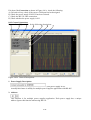
8.4.3 Data Logging and Setting Window in Application Software
Figure 8.4.3a Data Logging Function for a Single Power Supply
P.18
Page is loading ...
Page is loading ...
Page is loading ...
Page is loading ...
Page is loading ...
Page is loading ...
Page is loading ...
Page is loading ...
Page is loading ...
Page is loading ...
Page is loading ...
Page is loading ...
Page is loading ...
Page is loading ...
Page is loading ...
Page is loading ...
Page is loading ...
Page is loading ...
Page is loading ...
-
 1
1
-
 2
2
-
 3
3
-
 4
4
-
 5
5
-
 6
6
-
 7
7
-
 8
8
-
 9
9
-
 10
10
-
 11
11
-
 12
12
-
 13
13
-
 14
14
-
 15
15
-
 16
16
-
 17
17
-
 18
18
-
 19
19
-
 20
20
-
 21
21
-
 22
22
-
 23
23
-
 24
24
-
 25
25
-
 26
26
-
 27
27
-
 28
28
-
 29
29
-
 30
30
-
 31
31
-
 32
32
-
 33
33
-
 34
34
-
 35
35
-
 36
36
-
 37
37
-
 38
38
-
 39
39


Manson SDP-2405 User manual
- Type
- User manual
Ask a question and I''ll find the answer in the document
Finding information in a document is now easier with AI
Related papers
Other documents
-
B&K Precision Model 1696 User manual
-
Samsung SDP-950DXA User guide
-
-
UNI-T UT620A Digital Micro Ohm Meter User manual
-
-
Allen-Bradley 1763-L16BBB Instruction Set Reference Manual
-
Beijer Electronics QTERM-G55 User manual
-
WEG CFW-09 User manual
-
-
Optimus ACCS-S User manual