Page is loading ...

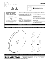
BQ
Faceplate
RELEASE DATE
5-19-16
REFERENCE NUMBER
INS-1455
40429 Brickyard Drive • Madera, CA 93636 • USA
559.438.5800 • FAX 559.438.5900
www.bklighting.com • [email protected]
B-K LIGHTING
THIS DOCUMENT CONTAINS PROPRIETARY INFORMATION OF B-K LIGHTING, INC. AND ITS RECEIPT OR POSSESSION DOES NOT CONVEY ANY RIGHTS TO REPRODUCE, DISCLOSE ITS CONTENTS, OR TO MANUFACTURE, USE OR SELL ANYTHING IT MAY
DESCRIBE. REPRODUCTION, DISCLOSURE OR USE WITHOUT SPECIFIC WRITTEN AUTHORIZATION OF B-K LIGHTING, INC. IS STRICTLY FORBIDDEN.
IMPORTANT SAFETY INFORMATION - READ, FOLLOW, AND SAVE THESE INSTALLATION INSTRUCTIONS
TOOLS
NEEDED:
By Others
1/8” Allen Wrench
Waterproof Wire Connectors
IMPORTANT NOTE
VQ and VQL mount in ceiling.
Orientation of installed back
box determines faceplate screw
orientation.
• Product must be installed by a qualified person in a manner
consistent with its intended use and in compliance with the
National Electrical Code, Canadian Electrical Code, and all Local
and Provincial Codes.
• Follow product label information and instructions.
• Qualified Personnel must perform all servicing or relamping of
this product.
• Before wiring to power supply and during servicing or relamping,
turn off power at fuse or circuit breaker before service.
• The use of accessory equipment not recommended by the
manufacturer or installed contrary to instructions may cause an
unsafe condition. The use of damaged components may cause
an unsafe condition and void product warranty.
IMPORTANT SAFETY INFORMATION - READ, FOLLOW, AND SAVE ALL SAFETY
AND INSTALLATION INSTRUCTIONS
• Do not block light emanating from product in whole or part,
as this may cause an unsafe condition.
• Never operate the fixture with missing or damaged lens.
Lens must be cleaned on regular basis.
• Entire fixture may become extremely hot. Do not touch hot
lens or fixture body. Do not touch the lamp at any time. Use
a clean, dry, soft cloth to handle the lamp. Oil from skin may
damage the lamp and cause it to rupture.
• Replace lamp only with correct wattage and type of lamp
marked on fixture label.
• All gaskets, o-rings and sealing surfaces must be kept clean
during installation and service; failure to do this may cause an
unsafe condition and void product warranty.
INSTRUCTIONS PERTAINING TO
A RISK OF FIRE, OR INJURY TO
PERSONS IMPORTANT SAFETY
INSTRUCTIONS
Lighted lamp is HOT!
WARNING - To reduce the risk of FIRE OR INJURY TO PERSONS:
Turn off/unplug and allow to cool before replacing lamp.
Lamp gets HOT quickly! Contact only switch/plug when
turning on.
Do not touch hot lens, guard, or enclosure (see diagram/
picture).
Keep lamp away from materials that may burn.
Do no touch the lamp at any time. Use a soft cloth. Oil
from skin may damage lamp.
Do not operate the luminaire fitting with a missing or
damaged shield.
SAVE THESE INSTRUCTIONS
· Suitable for wet location · Additionally suitable for mounting within 4 ft. of the ground • Type Non-IC
IMPORTANT LISTINGS AND CERTIFICATIONS
Hot Surface
Warning Low Voltage
BACK BOX
Low Voltage Halogen
Installation Instructions
Please refer to the low voltage design guide at www.bklighting.com/lvguide before installation for proper wire selection.
Socket
Assembly
BQL SQ SQL VQ VQLBQ
Rectangular Junction Box
(MB2) with Extension
This set of instructions works for:
BQ - Brick Star™
BQL - Louvered Brick Star™
SQ - Square Step Star™
SQL - Louvered Square Step Star™
VQ - Square Versa Star™
VQL - Louvered Square Versa Star™

RELEASE DATE
5-19-16
REFERENCE NUMBER
INS-1455
40429 Brickyard Drive • Madera, CA 93636 • USA
559.438.5800 • FAX 559.438.5900
www.bklighting.com • [email protected]
B-K LIGHTING
3. Re-insert socket assembly into faceplate.
Phase 2 - Finish Installation of Fixture with Remote Transformer
LINE 12V
Fixture
COM
Remote
Transformer
COM
IMPORTANT SAFETY INFORMATION LISTED ON REVERSE
READ, FOLLOW, AND SAVE ALL SAFETY AND INSTALLATION INSTRUCTIONS
WIRING DIAGRAM
Low Voltage - For use with 12VAC remote
transformer.
1. Remove socket assembly from faceplate housing.
Install lamp if needed. Do not exceed wattage on
label.
BACK BOX
Low Voltage Halogen
Installation Instructions
2. Make watertight connections from remote
transformer to lamp leads using waterproof
wire connectors. (By Others) See wiring
diagram.
Phase 1 - Rough In
Installation of Back box
2. Install Conduit (By Others) to be used with
this product.
5. Connect box to conduit and pull wires for
connections (See Wiring diagram).
Additional Info
• Please follow National and Local electrical codes for your area.
• Suitable for through wire.
• Suitable for installation into combustible materials.
• Rated for 90° C.
• Orientation of installed back box determines faceplate screw
orientation.
1. Remove canopy and/or fixture from MB2
housing. Ensure unused tapped holes are
plugged to maintain seal. Plugs are provided.
3. To prepare MB2 for mounting, align
mounting brackets on back of box. Brackets
can be aligned to vertical, horizontal or 45°
orientation. Secure with mounting screw
using screwdriver.
Install back box so that front face is flush
with finished wall or ceiling. Make sure
rectangular back box is plumb before
proceeding.
4. Mount MB2 box to surface using mounting
hardware (Provided) using the mounting
brackets attached to back of MB2 box.
Alternative mounting methods may
compromise integrity of MB2 against water
intrusion and will void warranty.
NOTE: Surface conduit is a common entrance
for water if not properly sealed. Seal
connector threads and conduit with a suitable
sealant (Teflon tape, adhesive, etc.). Sealing
the conduit after knockouts are removed is
required to maintain warranty.

4. Mount faceplate using two (2) #10-24 screws with
1/8” Allen wrench. Tighten to compress gasket. Do
not over tighten.
BACK BOX
Low Voltage Halogen
Installation Instructions
RELEASE DATE
5-19-16
REFERENCE NUMBER
INS-1455
40429 Brickyard Drive • Madera, CA 93636 • USA
559.438.5800 • FAX 559.438.5900
www.bklighting.com • [email protected]
B-K LIGHTING
IMPORTANT SAFETY INFORMATION LISTED ON REVERSE
READ, FOLLOW, AND SAVE ALL SAFETY AND INSTALLATION INSTRUCTIONS

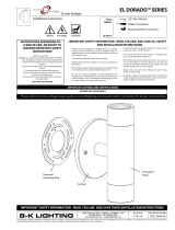
BQ
Rectangular Back Box
with Extension
Faceplate
RELEASE DATE
5-19-16
REFERENCE NUMBER
INS-1455-AJ
40429 Brickyard Drive • Madera, CA 93636 • USA
559.438.5800 • FAX 559.438.5900
www.bklighting.com • [email protected]
B-K LIGHTING
THIS DOCUMENT CONTAINS PROPRIETARY INFORMATION OF B-K LIGHTING, INC. AND ITS RECEIPT OR POSSESSION DOES NOT CONVEY ANY RIGHTS TO REPRODUCE, DISCLOSE ITS CONTENTS, OR TO MANUFACTURE, USE OR SELL ANYTHING IT MAY
DESCRIBE. REPRODUCTION, DISCLOSURE OR USE WITHOUT SPECIFIC WRITTEN AUTHORIZATION OF B-K LIGHTING, INC. IS STRICTLY FORBIDDEN.
IMPORTANT SAFETY INFORMATION - READ, FOLLOW, AND SAVE THESE INSTALLATION INSTRUCTIONS
TOOLS
NEEDED:
By Others
1/8” Allen Wrench
Waterproof Wire Connectors
Phillips Screwdriver
IMPORTANT NOTE
VQ and VQL mount in ceiling.
Orientation of installed back
box determines faceplate screw
orientation.
This set of instructions works for:
BQ - Brick Star™
BQL - Louvered Brick Star™
SQ - Square Step Star™
SQL - Louvered Square Step Star™
VQ - Square Versa Star™
VQL - Louvered Square Versa Star™
BQL SQ SQL VQ VQL
• Product must be installed by a qualified person in a manner
consistent with its intended use and in compliance with the
National Electrical Code, Canadian Electrical Code, and all Local
and Provincial Codes.
• Follow product label information and instructions.
• Qualified Personnel must perform all servicing or relamping of
this product.
• Before wiring to power supply and during servicing or relamping,
turn off power at fuse or circuit breaker before service.
• The use of accessory equipment not recommended by the
manufacturer or installed contrary to instructions may cause an
unsafe condition. The use of damaged components may cause
an unsafe condition and void product warranty.
IMPORTANT SAFETY INFORMATION - READ, FOLLOW, AND SAVE ALL SAFETY
AND INSTALLATION INSTRUCTIONS
• Do not block light emanating from product in whole or part,
as this may cause an unsafe condition.
• Never operate the fixture with missing or damaged lens.
Lens must be cleaned on regular basis.
• Entire fixture may become extremely hot. Do not touch hot
lens or fixture body. Do not touch the lamp at any time. Use
a clean, dry, soft cloth to handle the lamp. Oil from skin may
damage the lamp and cause it to rupture.
• Replace lamp only with correct wattage and type of lamp
marked on fixture label.
• All gaskets, o-rings and sealing surfaces must be kept clean
during installation and service; failure to do this may cause an
unsafe condition and void product warranty.
INSTRUCTIONS PERTAINING TO
A RISK OF FIRE, OR INJURY TO
PERSONS IMPORTANT SAFETY
INSTRUCTIONS
Lighted lamp is HOT!
WARNING - To reduce the risk of FIRE OR INJURY TO PERSONS:
Turn off/unplug and allow to cool before replacing lamp.
Lamp gets HOT quickly! Contact only switch/plug when
turning on.
Do not touch hot lens, guard, or enclosure (see diagram/
picture).
Keep lamp away from materials that may burn.
Do no touch the lamp at any time. Use a soft cloth. Oil
from skin may damage lamp.
Do not operate the luminaire fitting with a missing or
damaged shield.
SAVE THESE INSTRUCTIONS
· Suitable for wet location · Additionally suitable for mounting within 4 ft. of the ground • Type Non-IC
IMPORTANT LISTINGS AND CERTIFICATIONS
Hot Surface
Warning Low Voltage
BACK BOX
Low Voltage Halogen - Adjustable Bracket
Installation Instructions
BQ
Please refer to the low voltage design guide at www.bklighting.com/lvguide before installation for proper wire selection.
Adjustable
Bracket
Thumbscrew

RELEASE DATE
5-19-16
REFERENCE NUMBER
INS-1455-AJ
40429 Brickyard Drive • Madera, CA 93636 • USA
559.438.5800 • FAX 559.438.5900
www.bklighting.com • [email protected]
B-K LIGHTING
Phase 2 - Finish Installation of Fixture with Remote Transformer
LINE 12V
Fixture
COM
Remote
Transformer
COM
IMPORTANT SAFETY INFORMATION LISTED ON REVERSE
READ, FOLLOW, AND SAVE ALL SAFETY AND INSTALLATION INSTRUCTIONS
WIRING DIAGRAM
Low Voltage - For use with 12VAC remote
transformer.
1. To install lamp (if needed), remove socket assembly
from faceplate housing by loosening thumbscrew.
Do not exceed wattage on label.
BACK BOX
Low Voltage Halogen - Adjustable Bracket
Installation Instructions
3. Insert tab from socket into notch on adjustable
lamp bracket, then tighten thumbscrew.
2. Make watertight connections from remote
transformer to lamp leads using waterproof
wire connectors. (By Others) See wiring
diagram.
Phase 1 - Rough In
Installation of Back box
2. Install Conduit (By Others) to be used with
this product.
5. Connect box to conduit and pull wires for
connections (See Wiring diagram).
Additional Info
• Please follow National and Local electrical codes for your area.
• Suitable for through wire.
• Suitable for installation into combustible materials.
• Rated for 90° C.
• Orientation of installed back box determines faceplate screw
orientation.
1. Remove canopy and/or fixture from MB2
housing. Ensure unused tapped holes are
plugged to maintain seal. Plugs are provided.
3. To prepare MB2 for mounting, align
mounting brackets on back of box. Brackets
can be aligned to vertical, horizontal or 45°
orientation. Secure with mounting screw
using screwdriver.
Install back box so that front face is flush
with finished wall or ceiling. Make sure
rectangular back box is plumb before
proceeding.
4. Mount MB2 box to surface using mounting
hardware (Provided) using the mounting
brackets attached to back of MB2 box.
Alternative mounting methods may
compromise integrity of MB2 against water
intrusion and will void warranty.
NOTE: Surface conduit is a common entrance
for water if not properly sealed. Seal
connector threads and conduit with a suitable
sealant (Teflon tape, adhesive, etc.). Sealing
the conduit after knockouts are removed is
required to maintain warranty.

5. Mount faceplate using two (2) #10-24 screws
with 1/8” Allen wrench. Tighten to compress
gasket. Do not over tighten.
4. Loosen Phillips screws on adjustable lamp bracket
and aim lamp to desired angle. When angle is set,
tighten Phillips screw to lock in place.
Phillips Screw
BACK BOX
Low Voltage Halogen - Adjustable Bracket
Installation Instructions
RELEASE DATE
5-19-16
REFERENCE NUMBER
INS-1455-AJ
40429 Brickyard Drive • Madera, CA 93636 • USA
559.438.5800 • FAX 559.438.5900
www.bklighting.com • [email protected]
B-K LIGHTING
IMPORTANT SAFETY INFORMATION LISTED ON REVERSE
READ, FOLLOW, AND SAVE ALL SAFETY AND INSTALLATION INSTRUCTIONS

BQ
Rectangular Back Box
with Extension
Faceplate
RELEASE DATE
5-19-16
REFERENCE NUMBER
INS-1455-TP
40429 Brickyard Drive • Madera, CA 93636 • USA
559.438.5800 • FAX 559.438.5900
www.bklighting.com • [email protected]
B-K LIGHTING
THIS DOCUMENT CONTAINS PROPRIETARY INFORMATION OF B-K LIGHTING, INC. AND ITS RECEIPT OR POSSESSION DOES NOT CONVEY ANY RIGHTS TO REPRODUCE, DISCLOSE ITS CONTENTS, OR TO MANUFACTURE, USE OR SELL ANYTHING IT MAY
DESCRIBE. REPRODUCTION, DISCLOSURE OR USE WITHOUT SPECIFIC WRITTEN AUTHORIZATION OF B-K LIGHTING, INC. IS STRICTLY FORBIDDEN.
IMPORTANT SAFETY INFORMATION - READ, FOLLOW, AND SAVE THESE INSTALLATION INSTRUCTIONS
TOOLS
NEEDED:
By Others
1/8” Allen Wrench
Waterproof Wire Connectors
IMPORTANT NOTE
VQ and VQL mount in ceiling.
Orientation of installed back
box determines faceplate screw
orientation.
• Product must be installed by a qualified person in a manner
consistent with its intended use and in compliance with the
National Electrical Code, Canadian Electrical Code, and all Local
and Provincial Codes.
• Follow product label information and instructions.
• Qualified Personnel must perform all servicing or relamping of
this product.
• Before wiring to power supply and during servicing or relamping,
turn off power at fuse or circuit breaker before service.
• The use of accessory equipment not recommended by the
manufacturer or installed contrary to instructions may cause an
unsafe condition. The use of damaged components may cause
an unsafe condition and void product warranty.
IMPORTANT SAFETY INFORMATION - READ, FOLLOW, AND SAVE ALL SAFETY
AND INSTALLATION INSTRUCTIONS
• Do not block light emanating from product in whole or part,
as this may cause an unsafe condition.
• Never operate the fixture with missing or damaged lens.
Lens must be cleaned on regular basis.
• Entire fixture may become extremely hot. Do not touch hot
lens or fixture body. Do not touch the lamp at any time. Use
a clean, dry, soft cloth to handle the lamp. Oil from skin may
damage the lamp and cause it to rupture.
• Replace lamp only with correct wattage and type of lamp
marked on fixture label.
• All gaskets, o-rings and sealing surfaces must be kept clean
during installation and service; failure to do this may cause an
unsafe condition and void product warranty.
INSTRUCTIONS PERTAINING TO
A RISK OF FIRE, OR INJURY TO
PERSONS IMPORTANT SAFETY
INSTRUCTIONS
Lighted lamp is HOT!
WARNING - To reduce the risk of FIRE OR INJURY TO PERSONS:
Turn off/unplug and allow to cool before replacing lamp.
Lamp gets HOT quickly! Contact only switch/plug when
turning on.
Do not touch hot lens, guard, or enclosure (see diagram/
picture).
Keep lamp away from materials that may burn.
Do no touch the lamp at any time. Use a soft cloth. Oil
from skin may damage lamp.
Do not operate the luminaire fitting with a missing or
damaged shield.
SAVE THESE INSTRUCTIONS
· Suitable for wet location · Additionally suitable for mounting within 4 ft. of the ground • Type Non-IC
IMPORTANT LISTINGS AND CERTIFICATIONS
Hot Surface
Warning Low Voltage
BACK BOX
Low Voltage Halogen - Thermal Protector
Installation Instructions
Please refer to the low voltage design guide at www.bklighting.com/lvguide before installation for proper wire selection.
Thermal
Protector
Connector
Socket
Assembly
BQL SQ SQL VQ VQLBQ
This set of instructions works for:
BQ - Brick Star™
BQL - Louvered Brick Star™
SQ - Square Step Star™
SQL - Louvered Square Step Star™
VQ - Square Versa Star™
VQL - Louvered Square Versa Star™

RELEASE DATE
5-19-16
REFERENCE NUMBER
INS-1455-TP
40429 Brickyard Drive • Madera, CA 93636 • USA
559.438.5800 • FAX 559.438.5900
www.bklighting.com • [email protected]
B-K LIGHTING
Phase 2 - Finish Installation of Fixture with Remote Transformer
Red
LAMP
QUICK
DISCONNECT
REMOTE
TRANSFORMER
THERMAL
PROTECTOR
LINE
C
OMMON
Red
White
White
Yellow
White
White
White
Black
IMPORTANT SAFETY INFORMATION LISTED ON REVERSE
READ, FOLLOW, AND SAVE ALL SAFETY AND INSTALLATION INSTRUCTIONS
2. Make watertight connections from remote
transformer to thermal protector using
waterproof wire connectors. (By Others) See
wiring diagram.
WIRING DIAGRAM
Low Voltage - For use with 12VAC remote
transformer.
1. Remove socket assembly from faceplate housing.
Install lamp if needed. Do not exceed wattage on
label.
BACK BOX
Low Voltage Halogen - Thermal Protector
Installation Instructions
3. Connect quick disconnect from thermal protector
to lamp leads.
4. Re-insert socket assembly into faceplate.
Phase 1 - Rough In
Installation of Back box
2. Install Conduit (By Others) to be used with
this product.
5. Connect box to conduit and pull wires for
connections (See Wiring diagram).
Additional Info
• Please follow National and Local electrical codes for your area.
• Suitable for through wire.
• Suitable for installation into combustible materials.
• Rated for 90° C.
• Orientation of installed back box determines faceplate screw
orientation.
1. Remove canopy and/or fixture from MB2
housing. Ensure unused tapped holes are
plugged to maintain seal. Plugs are provided.
3. To prepare MB2 for mounting, align
mounting brackets on back of box. Brackets
can be aligned to vertical, horizontal or 45°
orientation. Secure with mounting screw
using screwdriver.
Install back box so that front face is flush
with finished wall or ceiling. Make sure
rectangular back box is plumb before
proceeding.
4. Mount MB2 box to surface using mounting
hardware (Provided) using the mounting
brackets attached to back of MB2 box.
Alternative mounting methods may
compromise integrity of MB2 against water
intrusion and will void warranty.
NOTE: Surface conduit is a common entrance
for water if not properly sealed. Seal
connector threads and conduit with a suitable
sealant (Teflon tape, adhesive, etc.). Sealing
the conduit after knockouts are removed is
required to maintain warranty.

5. Mount faceplate using two (2) #10-24 screws with
1/8” Allen wrench. Tighten to compress gasket. Do
not over tighten.
BACK BOX
Low Voltage Halogen - Thermal Protector
Installation Instructions
RELEASE DATE
5-19-16
REFERENCE NUMBER
INS-1455-TP
40429 Brickyard Drive • Madera, CA 93636 • USA
559.438.5800 • FAX 559.438.5900
www.bklighting.com • [email protected]
B-K LIGHTING
IMPORTANT SAFETY INFORMATION LISTED ON REVERSE
READ, FOLLOW, AND SAVE ALL SAFETY AND INSTALLATION INSTRUCTIONS

BQ
Rectangular Back Box
with Extension
RELEASE DATE
5-19-16
REFERENCE NUMBER
INS-1455-AJ-TP
40429 Brickyard Drive • Madera, CA 93636 • USA
559.438.5800 • FAX 559.438.5900
www.bklighting.com • [email protected]
B-K LIGHTING
THIS DOCUMENT CONTAINS PROPRIETARY INFORMATION OF B-K LIGHTING, INC. AND ITS RECEIPT OR POSSESSION DOES NOT CONVEY ANY RIGHTS TO REPRODUCE, DISCLOSE ITS CONTENTS, OR TO MANUFACTURE, USE OR SELL ANYTHING IT MAY
DESCRIBE. REPRODUCTION, DISCLOSURE OR USE WITHOUT SPECIFIC WRITTEN AUTHORIZATION OF B-K LIGHTING, INC. IS STRICTLY FORBIDDEN.
IMPORTANT SAFETY INFORMATION - READ, FOLLOW, AND SAVE THESE INSTALLATION INSTRUCTIONS
TOOLS
NEEDED:
By Others
1/8” Allen Wrench
Waterproof Wire Connectors
Phillips Screwdriver
IMPORTANT NOTE
VQ and VQL mount in ceiling.
Orientation of installed back
box determines faceplate screw
orientation.
This set of instructions works for:
BQ - Brick Star™
BQL - Louvered Brick Star™
SQ - Square Step Star™
SQL - Louvered Square Step Star™
VQ - Square Versa Star™
VQL - Louvered Square Versa Star™
BQL SQ SQL VQ VQL
• Product must be installed by a qualified person in a manner
consistent with its intended use and in compliance with the
National Electrical Code, Canadian Electrical Code, and all Local
and Provincial Codes.
• Follow product label information and instructions.
• Qualified Personnel must perform all servicing or relamping of
this product.
• Before wiring to power supply and during servicing or relamping,
turn off power at fuse or circuit breaker before service.
• The use of accessory equipment not recommended by the
manufacturer or installed contrary to instructions may cause an
unsafe condition. The use of damaged components may cause
an unsafe condition and void product warranty.
IMPORTANT SAFETY INFORMATION - READ, FOLLOW, AND SAVE ALL SAFETY
AND INSTALLATION INSTRUCTIONS
• Do not block light emanating from product in whole or part,
as this may cause an unsafe condition.
• Never operate the fixture with missing or damaged lens.
Lens must be cleaned on regular basis.
• Entire fixture may become extremely hot. Do not touch hot
lens or fixture body. Do not touch the lamp at any time. Use
a clean, dry, soft cloth to handle the lamp. Oil from skin may
damage the lamp and cause it to rupture.
• Replace lamp only with correct wattage and type of lamp
marked on fixture label.
• All gaskets, o-rings and sealing surfaces must be kept clean
during installation and service; failure to do this may cause an
unsafe condition and void product warranty.
INSTRUCTIONS PERTAINING TO
A RISK OF FIRE, OR INJURY TO
PERSONS IMPORTANT SAFETY
INSTRUCTIONS
Lighted lamp is HOT!
WARNING - To reduce the risk of FIRE OR INJURY TO PERSONS:
Turn off/unplug and allow to cool before replacing lamp.
Lamp gets HOT quickly! Contact only switch/plug when
turning on.
Do not touch hot lens, guard, or enclosure (see diagram/
picture).
Keep lamp away from materials that may burn.
Do no touch the lamp at any time. Use a soft cloth. Oil
from skin may damage lamp.
Do not operate the luminaire fitting with a missing or
damaged shield.
SAVE THESE INSTRUCTIONS
· Suitable for wet location · Additionally suitable for mounting within 4 ft. of the ground • Type Non-IC
IMPORTANT LISTINGS AND CERTIFICATIONS
Hot Surface
Warning Low Voltage
BACK BOX
Low Voltage Halogen - Adjustable Bracket and Thermal Protector
Installation Instructions
BQ
Please refer to the low voltage design guide at www.bklighting.com/lvguide before installation for proper wire selection.
Faceplate
Thermal Protector
Adjustable
Bracket
Connector
Thumbscrew

RELEASE DATE
5-19-16
REFERENCE NUMBER
INS-1455-AJ-TP
40429 Brickyard Drive • Madera, CA 93636 • USA
559.438.5800 • FAX 559.438.5900
www.bklighting.com • [email protected]
B-K LIGHTING
Phase 2 - Finish Installation of Fixture with Remote Transformer
Red
LAMP
QUICK
DISCONNECT
REMOTE
TRANSFORMER
THERMAL
PROTECTOR
LINE
C
OMMON
Red
White
White
Yellow
White
White
White
Black
IMPORTANT SAFETY INFORMATION LISTED ON REVERSE
READ, FOLLOW, AND SAVE ALL SAFETY AND INSTALLATION INSTRUCTIONS
2. Make watertight connections from remote
transformer to thermal protector using
waterproof wire connectors. (By Others) See
wiring diagram.
WIRING DIAGRAM
Low Voltage - For use with 12VAC remote
transformer.
BACK BOX
Low Voltage Halogen - Adjustable Bracket and Thermal Protector
Installation Instructions
3. Connect quick disconnect from thermal protector
to lamp leads.
1. To install lamp (if needed), remove socket assembly
from faceplate housing by loosening thumbscrew.
Do not exceed wattage on label.
Phase 1 - Rough In
Installation of Back box
2. Install Conduit (By Others) to be used with
this product.
5. Connect box to conduit and pull wires for
connections (See Wiring diagram).
Additional Info
• Please follow National and Local electrical codes for your area.
• Suitable for through wire.
• Suitable for installation into combustible materials.
• Rated for 90° C.
• Orientation of installed back box determines faceplate screw
orientation.
1. Remove canopy and/or fixture from MB2
housing. Ensure unused tapped holes are
plugged to maintain seal. Plugs are provided.
3. To prepare MB2 for mounting, align
mounting brackets on back of box. Brackets
can be aligned to vertical, horizontal or 45°
orientation. Secure with mounting screw
using screwdriver.
Install back box so that front face is flush
with finished wall or ceiling. Make sure
rectangular back box is plumb before
proceeding.
4. Mount MB2 box to surface using mounting
hardware (Provided) using the mounting
brackets attached to back of MB2 box.
Alternative mounting methods may
compromise integrity of MB2 against water
intrusion and will void warranty.
NOTE: Surface conduit is a common entrance
for water if not properly sealed. Seal
connector threads and conduit with a suitable
sealant (Teflon tape, adhesive, etc.). Sealing
the conduit after knockouts are removed is
required to maintain warranty.

6. Re-insert socket assembly into faceplate.
7. Mount faceplate using two (2) #10-24 screws with
1/8” Allen wrench. Tighten evenly to compress
gasket. Do not over tighten.
5. Loosen Phillip screws on adjustable lamp
bracket and aim lamp to desired angle. When
angle is set, tighten Phillip screw to lock in
place.
4. Insert tab from socket into notch on adjustable
lamp bracket, then tighten thumbscrew.
Phillip Screw
BACK BOX
Low Voltage Halogen - Adjustable Bracket and Thermal Protector
Installation Instructions
RELEASE DATE
5-19-16
REFERENCE NUMBER
INS-1455-AJ-TP
40429 Brickyard Drive • Madera, CA 93636 • USA
559.438.5800 • FAX 559.438.5900
www.bklighting.com • [email protected]
B-K LIGHTING
IMPORTANT SAFETY INFORMATION LISTED ON REVERSE
READ, FOLLOW, AND SAVE ALL SAFETY AND INSTALLATION INSTRUCTIONS
/