Page is loading ...

MODELS COVERED IN THIS MANUAL:
AJ-44CGP AJ-54CGP
AJ-66CGP AJ-76CGP
AJ-80CGP AJ-90CGP
II
NN
SS
TT
AA
LL
LL
AA
TT
II
OO
NN
&&
OO
PP
EE
RR
AA
TT
II
OO
NN
MM
AA
NN
UU
AA
LL
www.jacksonmsc.com
AJ-44/AJ-54 SERIES RACK CONVEYOR DISHMACHINES
(GAS HEATED)
October 5, 2001
P/N 7610-002-40-99 (Rev. A)

MANUFACTURERS WARRANTY
ONE YEAR LIMITED PARTS & LABOR WARRANTY
ALL NEW JACKSON DISHWASHERS ARE WARRANTED TO THE ORIGINAL PURCHASER TO BE FREE FROM
DEFECTS IN MATERIAL OR WORKMANSHIP, UNDER NORMAL USE AND OPERATION FOR A PERIOD OF (1) ONE
YEAR FROM THE DATE OF PURCHASE, BUT IN NO EVENT TO EXCEED (18) EIGHTEEN MONTHS FROM THE DATE
OF SHIPMENT FROM THE FACTORY.
Jackson MSC agrees under this warranty to repair or replace , at its discretion, any original part which fails under normal use due to faulty
material or workmanship during the warranty period, providing the equipment has been unaltered, and has been properly installed, main-
tained and operated in accordance with the applicable factory instruction manual furnished with the machine and the failure is reported to
the authorized service agency within the warranty period. This includes the use of factory specified genuine replacement parts, purchased
directly from a Jackson authorized parts distributor or service agency. Use of generic replacement parts may create a hazard and void war-
ranty certification.
The labor to repair or replace such failed part will be paid by Jackson MSC, within the continental United States, Hawaii and Canada, dur-
ing the warranty period provided a Jackson MSC authorized service agency, or those having prior authorization from the factory, performs
the service. Any repair work by persons other than a Jackson MSC authorized service agency is the sole responsibility of the customer.
Labor coverage is limited to regular hourly rates, overtime premiums and emergency service charges will not be paid by Jackson MSC.
Accessory components not installed by the factory carry a (1) one year parts warranty only. Accessory components such as table limit
switches, pressure regulators, pre rinse units, etc. that are shipped with the unit and installed at the site are included. Labor to repair or
replace these components is not covered by Jackson MSC.
This warranty is void if failure is a direct result from shipping, handling, fire, water, accident, misuse, acts of god, attempted repair by unau-
thorized persons, improper installation, if serial number has been removed or altered, or if unit is used for purpose other than it was origi-
nally intended.
TRAVEL LIMITATIONS
Jackson MSC limits warranty travel time to (2) two hours and mileage to (100) one hundred miles. Jackson MSC will not pay for travel time
and mileage that exceeds this, or any fees such as those for air or boat travel without prior authorization.
WARRANTY REGISTRATION CARD
The warranty registration card supplied with the machine must be returned to Jackson MSC within 30 days to validate the warranty.
REPLACEMENT PARTS WARRANTY
Jackson replacement parts are warranted for a period of 90 days from the date of installation or 180 days from the date of shipment from
the factory, which ever occurs first.
PRODUCT CHANGES AND UPDATES
Jackson MSC reserves the right to make changes in design and specification of any equipment as engineering or necessity requires.
THIS IS THE ENTIRE AND ONLY WARRANTY OF JACKSON MSC. JACKSON’S LIABILITY ON ANY CLAIM OF ANY KIND, INCLUDING
NEGLIGENCE, WITH RESPECT TO THE GOODS OR SERVICES COVERED HEREUNDER, SHALL IN NO CASE EXCEED THE PRICE
OF THE GOODS OR SERVICES OR PART THEREOF WHICH GIVES RISE TO THE CLAIM.
THERE ARE NO WARRANTIES, EXPRESSED OR IMPLIED, INCLUDING FOR FITNESS OR MERCHANTABILITY, THAT ARE NOT SET
FORTH HEREIN, OR THAT EXTEND BEYOND THE DURATION HEREOF. UNDER NO CIRCUMSTANCES WILL JACKSON MSC BE
LIABLE FOR ANY LOSS OR DAMAGE, DIRECT OR CONSEQUENTIAL, OR FOR THE DAMAGES IN THE NATURE OF PENALTIES,
ARISING OUT OF THE USE OR INABILITY TO USE ANY OF ITS PRODUCTS.
ITEMS NOT COVERED
This warranty does not cover cleaning or deliming of the unit or any component such as, but not limited to, wash arms, rinse arms, or strain-
ers at anytime. Nor does it cover adjustments such as, but not limited to, timer cams, thermostats or doors, beyond 30 days from the date
of installation. In addition, the warranty will only cover the replacement of wear items such as curtains, drain balls, door guides or gaskets
during the first 30 days after installation. Also not covered are conditions caused by the use of incorrect (non-Commercial) grade detergents,
incorrect water temperature or pressure, or hard water conditions.

SECTION DESCRIPTION PAGE
I. GENERAL SECTION
Specifications (AJ-44CGP, AJ-66CGP, AJ-80CGP) 1
Specifications (AJ-54CGP, AJ-76CGP, AJ-90CGP) 2
II. INSTALLATION & OPERATION SECTION
Installation Instructions 3
Hose Connections 5
Detergent Control 7
Operation Instructions 8
III. DIMENSIONS
AJ-44 Dimensions 9
AJ-54 Dimensions 10
AJ-66 (Left to Right) Dimensions 11
AJ-66 (Right to Left) Dimensions 12
AJ-76 (Left to Right) Dimensions 13
AJ-76 (Right to Left) Dimensions 14
AJ-80 (Left to Right) Dimensions 15
AJ-80 (Right to Left) Dimensions 16
AJ-90 (Left to Right) Dimensions 17
AJ-90 (Right to Left) Dimensions 18
IV. JACKSON MAINTENANCE & REPAIR CENTERS 19
V. ELECTRICAL DIAGRAMS
AJ-44CGP & AJ-54CGP (208-230V/60 Hz/1 Phase) Schematic 24
AJ-44CGP & AJ-54CGP (208-230V/60 Hz/3 Phase) Schematic 25
AJ-44CGP & AJ-54CGP (460V/60 Hz/3 Phase) Schematic 26
AJ-66CGP, AJ-76CGP, AJ-80CGP & AJ-90CGP (208-230V/60 Hz/1 Phase) Schematic 27
AJ-66CGP, AJ-76CGP, AJ-80CGP & AJ-90CGP (208-230V/60 Hz/3 Phase) Schematic 28
AJ-66CGP, AJ-76CGP, AJ-80CGP & AJ-90CGP (480V/60 Hz/3 Phase) Schematic 29
VI. IMPORTANT INFORMATION DATA SHEET 30
TABLE OF CONTENTS
i

SPECIFICATIONS (AJ-44CGP, AJ-66CGP & AJ-80CGP)
1
Drive Motor Prewash Motor Wash Motor Total
Model Volts Phase Hz HP Amps HP Amps HP Amps Amps
AJ-44CGP 208 1 60 1/4 1.8 N/A N/A 2 8.5 10.3
AJ-44CGP 230 1 60 1/4 1.8 N/A N/A 2 8.5 10.3
AJ-44CGP 208 3 60 1/4 1.1 N/A N/A 2 5.6 6.7
AJ-44CGP 230 3 60 1/4 1.1 N/A N/A 2 5.6 6.7
AJ-44CGP 460 3 60 1/4 0.55 N/A N/A 2 2.8 3.35
AJ-66CGP 208 1 60 1/4 1.8 1 6 2 8.5 16.3
AJ-66CGP 230 1 60 1/4 1.8 1 6 2 8.5 16.3
AJ-66CGP 208 3 60 1/4 1.1 1 3.4 2 5.6 10.1
AJ-66CGP 230 3 60 1/4 1.1 1 3.4 2 5.6 10.1
AJ-66CGP 460 3 60 1/4 0.55 1 1.7 2 2.8 5.05
AJ-80CGP 208 1 60 1/4 1.8 2 8.5 2 8.5 18.8
AJ-80CGP 230 1 60 1/4 1.8 2 8.5 2 8.5 18.8
AJ-80CGP 208 3 60 1/4 1.1 2 5.6 2 5.6 12.3
AJ-80CGP 230 3 60 1/4 1.1 2 5.6 2 5.6 12.3
AJ-80CGP 460 3 60 1/4 0.55 2 2.8 2 2.8 6.15
RACKS PER HOUR:
AJ-44CGP: 248
AJ-66CGP: 248
AJ-80CGP: 248
DISHES OR GLASSES PER HOUR:
AJ-44CGP: 6200
AJ-66CGP: 6200
AJ-80CGP: 6200
WASH TANK CAPAITY (GALLONS):
ALL MODELS: 15.4
PREWASH TANK CAPACITY (GALLONS):
AJ-66 MODELS: 16
AJ-80 MODELS: 16
WASH PUMP CAPACITY:
GALLONS PER MINUTE: 270
PREWASH PUMP CAPACITY (GPM):
AJ-66 MODELS: 120
AJ-80 MODELS: 270
VENTING REQUIREMENTS (CFM)(100% CAP.):
INPUT END: 200
OUTPUT END: 400
TOTAL: 600
CONVEYOR SPEED (FPM):
CGP MACHINES: 6.9
GALLONS PER RACK:
CGP MACHINES: .94
WATER TEMPERATURES (
°
F):
PREWASH (MINIMUM) 110
WASH (MINIMUM) 160
RINSE (MINIMUM) 180
FLOW PRESSSURE (PSI) 20
FLOWRATE (GPM) 3.9

SPECIFICATIONS (AJ-54CGP, AJ-76CGP & AJ-90CGP)
2
Drive Motor Prewash Motor Wash Motor Heater Load Total
Model Volts Phase Hz HP Amps HP Amps HP Amps KW Amps Amps
AJ-54CGP 208 1 60 1/4 1.8 N/A N/A 2 8.5 N/A N/A 10.3
AJ-54CGP 230 1 60 1/4 1.8 N/A N/A 2 8.5 N/A N/A 10.3
AJ-54CGP 208 3 60 1/4 1.1 N/A N/A 2 5.6 N/A N/A 6.7
AJ-54CGP 230 3 60 1/4 1.1 N/A N/A 2 5.6 N/A N/A 6.7
AJ-54CGP 460 3 60 1/4 0.55 N/A N/A 2 2.8 N/A N/A 3.4
AJ-76CGP 208 1 60 1/4 1.8 1 6 2 8.5 N/A N/A 16.3
AJ-76CGP 230 1 60 1/4 1.8 1 6 2 8.5 N/A N/A 16.3
AJ-76CGP 208 3 60 1/4 1.1 1 3.4 2 5.6 N/A N/A 11.1
AJ-76CGP 230 3 60 1/4 1.1 1 3.4 2 5.6 N/A N/A 11.1
AJ-76CGP 460 3 60 1/4 0.55 1 1.7 2 2.8 N/A N/A 5.1
AJ-90CGP 208 1 60 1/4 1.8 2 8.5 2 8.5 N/A N/A 18.8
AJ-90CGP 230 1 60 1/4 1.8 2 8.5 2 8.5 N/A N/A 18.8
AJ-90CGP 208 3 60 1/4 1.1 2 5.6 2 5.6 N/A N/A 13.3
AJ-90CGP 230 3 60 1/4 1.1 2 5.6 2 5.6 N/A N/A 13.3
AJ-90CGP 460 3 60 1/4 0.55 2 2.8 2 2.8 N/A N/A 6.2
RACKS PER HOUR:
AJ-54CGP: 288
AJ-76CGP: 288
AJ-90CGP: 288
DISHES OR GLASSES PER HOUR:
AJ-54CGP: 7200
AJ-76CGP: 7200
AJ-90CGP: 7200
WASH TANK CAPAITY (GALLONS):
ALL MODELS: 15.4
PREWASH TANK CAPACITY (GALLONS):
AJ-76 MODELS: 16
AJ-90 MODELS: 16
WASH PUMP CAPACITY:
GALLONS PER MINUTE: 270
PREWASH PUMP CAPACITY (GPM):
AJ-76 MODELS: 120
AJ-90 MODELS: 270
VENTING REQUIREMENTS (CFM)(100% CAP.):
INPUT END: 200
OUTPUT END: 400
TOTAL: 600
CONVEYOR SPEED (FPM):
CGP MACHINES: 8.0
GALLONS PER RACK:
CGP MACHINES: 1.21
WATER TEMPERATURES (
°
F):
PREWASH (MINIMUM) 110
WASH (MINIMUM) 160
RINSE (MINIMUM) 180
FLOW PRESSSURE (PSI) 20
FLOWRATE (GPM) 5.9

NOTE: THE INSTRCUTION PROVIDED HEREIN, UNLESS
OTHERWISE SPECIFIED ARE FOR THE PHYSICAL DISHMA-
CHINE ONLY. THERE ARE SEPERATE DIRECTIONS FOR THE
GAS BOOSTER.
VISUAL INSPECTION: Before installing the unit, check the con-
tainer and machine for damage. A damaged container is an indi-
cator that there may be some damage to the machine. If there is
damage to both the container and machine, do not throw away the
container. The dishmachine has been inspected and packed at
the factory and is expected to arrive to you in new, undamaged
condition. However, rough handling by carriers or others may
result in there being damage to the unit while in transit. If such a
situation occurs, do not return the unit to Jackson; instead, contact
the carrier and ask them to send a representative to the site to
inspect the damage to the unit and to complete an inspection
report. You must contact the carrier within 48 hours of receiving
the machine. Also, contact the dealer through which you pur-
chased the unit.
UNPACKING THE DISHMACHINE: Once the machine has been
removed from the container, ensure that there are no missing
parts from the machine. This may not be obvious at first. If it is dis-
covered that an item is missing, contact Jackson immediately to
have the missing item shipped to you.
LEVEL THE DISHMACHINE: The dishmachine is designed to
operate while being level. This is important to prevent any dam-
age to the machine during operation and to ensure the best
results when washing ware. The unit comes with adjustable bullet
feet, which can be turned using a pair of channel locks or by hand
if the unit can be raised safely. Ensure that the unit is level from
side to side and from front to back before making any connec-
tions.
PLUMBING THE DISHMACHINE: All plumbing connections must
comply with all applicable local, state, and national plumbing
codes. The plumber is responsible for ensuring that the incoming
water line is throroughly flushed prior to connecting it to any com-
ponent of the dishmachine. It is necessary to remove all foreign
debris from the water line that may potentially get trapped in the
valves or cause an obstruction. Any valves that are fouled as a
result of foreign matter left in the water line, and any expenses
resulting from this fouling, are not the responsibility of the manu-
facturer.
CONNECTING THE DRAIN LINE: The drain for the models cov-
ered in this manual are gravity disharge drains. All piping from the
1-1/2” FNPT connection on the waste accumulator must be
pitched (1/4” per foot) to the floor or sink drain. All piping from the
machine to the drain must be a minimum 1-1/2” I.P.S. and shall not
be reduced. There must also be an air gap between the machine
drain line and the floor sink or drain. If a grease trap is required by
code, it should have a flow capacity of 30 gallons per minute.
WATER SUPPLY CONNECTION: Ensure that you have read the
section entitled “PLUMBING THE DISHMACHINE” above before
proceding. Install the water supply line (3/4” pipe size minimum) to
the dishmachine line strainer using copper pipe. It is recommend-
ed that a water shut-off valve be installed in the water line between
the main supply and the machine to allow access for service.
The water supply line is to be capable of 25 PSI “flow” pressure at
the recommended temperature indicated on the data plate.
In areas where the water pressure fluctuates or is greater than the
recommended pressure, it is suggested that a water pressure reg-
ulator be installed. The models covered in this manual do not
come with water pressure regulators as standard equipment.
Do not confuse static pressure with flow pressure. Static pressure
is the line pressure in a “no flow” condition (all valves and services
are closed). Flow pressure is the pressure in the fill line when the
fill valve is opened during the cycle.
It is also recommended that a shock absorber (not supplied) be
installed in the incoming water line. This prevents line hammer
(hydraulic shock), induced by the solenoid valve as it operates,
from causing damage to the equipment.
PLUMBING CHECK: Slowly turn on the water supply to the
machine after the incoming fill line and the drain line have been
installed. Check for any leaks and repair as required. All leaks
must be repaired prior to placing the machine in operation.
ELECTRICAL POWER CONNECTION: Electrical and grounding
connections must comply with the applicable portions of the
National Electrical Code ANSI/NFPA 70 (latest edition) and/or
other electrical codes.
Disconnect electrical power supply and place a tag at the discon-
nect switch to indicate that you are working on the circuit.
The dishmachine data plate is located on the right side and to the
front of the machine. Refer to the data plate for machine operat-
ing requirements, machine voltage, total amperage load and seri-
al number.
To install the incoming power lines, open the control box. Install
conduit into the pre-punched holes in the back of the control box.
Route power wires and connect to power block and grounding lug.
Install the service wires (L1, L2, and L3 (3 phase only)) to the
appropriate terminals as they are marked on the terminal block.
Install the grounding wire into the lug provided. Tighten the con-
nections. It is recommended that “DE-OX” or another similar anti-
oxidation agent be used on all power connections.
VOLTAGE CHECK: Ensure that the power switch is in the OFF
position and apply power to the dishmachine. Check the incoming
power at the terminal block and ensure it corresponds to the volt-
age listed on the data plate. If not, contact a qualified service
agency to examine the problem. Do not run the dishmachine if the
voltage is too high or too low. Shut off the service breaker and
mark it as being for the dishmachine. Advise all proper personnel
of any problems and of the location of the service breaker.
Replace the control box cover and tighten down the screws.
VENTILATION OF DISHMACHINE: The dishmachine should be
located with provisions for venting into an adequate exhaust hood
or ventilation system. This is essential to permit efficient removal
of the condensation exhaust. Ensure that the exhaust system is
acceptable in accordance with all applicable codes and standards.
INSTALLATION INSTRUCTIONS
3

NOTE: Damage caused by steam or moisture due to improp-
er ventilation is NOT covered under the warranty.
This units covered in this manual have the following exhaust
requirements:
Load End: 200 CFM
Unload End: 400 CFM
The exhaust system must be sized to handle this volume for the
dishmachine to operate as it was designed to.
THERMOSTATS: The thermostats for the machines covered in
this manual are factory set. They should not be adjusted except by
an authorized service agent.
DETERGENT: Detergent may be introduced into the unit through
the removal of the bulkhead plug in the rear of the tub and replac-
ing it with the third party detergent injection fitting. Remove the
bulkhead plug in the side of the tub to install the detergent con-
centration probe.
For more information concerning detergent concerns, please refer
to the page entitled “Detergent Control”.
The 1/8” brass plugs on the incoming plumbing rinse injector may
be removed to install sanitizer and rinse aid injection fittings.
All wires for the chemical injectors should be routed through the
back of the control box.
Terminals in the control box marked “CVS” provide a constant volt-
age signal whenever the drive motor is operating.
Terminals in the control box marked “DET” provide a voltage sig-
nal whenever the wash motor is operating.
DELIMING OPERATIONS: In order to maintain the dishmachine
at its optimum performance level, it will be required to remove lime
and corrosion deposits on a frequent basis. A deliming solution
should be available from your detergent supplier. Read and follow
all instructions on the label of the deliming solution.
To proceed with the deliming operation, fill the dishmachine and
add the correct amount of deliming solution as recommended by
the deliming solution manufacturer. The water capacity of the var-
ious tanks of the dishmachine can be verified on the specification
sheet(s) of this manual.
Perform the following operations to delime the dishmachine:
1. Turn the NORMAL/DELIME switch on the back of the control
box to the DELIME position.
2. Disconnect or turn off all chemical feeder pumps.
3. Close all doors (after adding the deliming solution).
4. Run the machine for the recommended period of time.
5. Turn the unit off and open the doors.
6. Wait five minutes, then inspect the inside of the machine. If the
machine is not delimed, run another time cycle as per the delim-
ing solution’s instructions.
7. When clean, drain and re-fill the machine.
8. Run in MANUAL for 10 minutes to remove residual deliming
solution.
9. Drain and re-fill the machine.
INSTALLATION INSTRUCTIONS (CONTINUED)
4

Due to the fact that each customer may have different requirements for the orientation of the gas booster heater relative to the main
dishmachine, the hose lengths that connect the two units must be customized during each installation. The appropriate 3/4” hosing, fit-
tings and gaskets have been provided.
To prevent incorrect measurements of the hose, it is recommended to place one barbed hose fitting into the end of the uncut length of
hose coil and attach that fitting to an appropriate connection. Run the hose to the corresponding connection on the other unit before
cutting the hose. Use a barbed hose fitting that is screwed into the second connection on the other unit before cutting the hose. Use a
barbed hose fitting that is screwed onto the second connection to gauge the correct distance. Ensure a smooth “flow” of hose without
any sharp turns or kinks.
To aid in pushing the barbed hose fitting into the hose, place the fitting on a hard surface (i.e. the floor) with the barbed end of the fit-
ting pointing upward and push the hose down onto the fitting. A small amount of lubricant (i.e. petroleum jelly) may aid in this process.
HOSE CONNECTIONS
5
Barbed Hose Fitting
Connection
Attach the hose fitting to
this connection before
making the cut at the
other end of the hose.
Hose
Cut the hose at the location where
the hose is even with the yellow
plastic stop.

HOSE CONNECTIONS (CONTINUED)
6
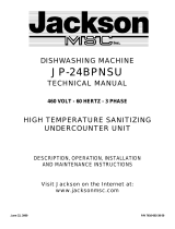
The illustrations below depict the typical hosing connection points for a gas-heated conveyor as seen from behind the unit. Figure
1 shows the hosing run when the gas booster heater is positioned to the LEFT of the unit. Figure 2 shows the hosing run when the
gas booster heater is positioned to the RIGHT of the unit.
Figure 1
Figure 2
Booster Tank
From discharge of
booster heater
To inlet of booster tank
Ensure a smooth “flow” of hose without any sharp turns
or kinks. Plumbing with copper tubing and fittings may
also be used instead of the flexible hosing.
To inlet of booster heater
From discharge of booster heater

Detergent usage and water hardness are two factors that contribute greatly to how efficiently your dishmachine will operate. Using
detergent in the proper amount can become, in time, a source of substantial savings. A qualified water treatment specialist can tell you
what is needed for maximum efficiency from your detergent, but you should still know some basics so you’ll understand what they are
talking about.
First, you must understand that hard water greatly effects the performance of the dishmachine. Water hardness is the amount of dis-
solved calcium and magnesium in the water supply. The more dissolved solids in the water, the greater the water hardness. Hard water
works against detergent, thereby causing the amount of detergent required for washing to increase. As you use more detergent, your
costs for operating the dishmachine will increase and the results will decrease. The solids in hard water also may build-up as a scale
on wash and rinse heaters, decreasing their ability to heat water. Water temperature is important in removing soil and sanitizing dish-
es. If the water cannot get hot enough, your results may not be satisfactory. This is why Jackson recommends that if you have installed
the machine in an area with hard water, that you also install some type of water treatment equipment to help remove the dissolved
solids from the water before it gets to the dishmachine.
Second, hard water may have you adding drying agents to your operating cycle to prevent spotting, when the real problem is deposit-
ed solids on your ware. As the water evaporates off of the ware, the solids will be left behind to form the spotting and no amount of dry-
ing agent will prevent this. Again, using treated water will undoubtedly reduce the occurences of this problem.
Third, treated water may not be suitable for use in other areas of your operation. For instance, coffee made with soft water may have
an acid or bitter flavor. It may only be feasible to install a small treatment unit for the water going into the dishmachine itself. Discuss
this option with your qualified water treatment specialist.
Even after the water hardness problems have been solved, there still must be proper training of dishmachine operators in how much
detergent is to be used per cycle. Talk with your water treatment specialist and detergent vendor and come up with a complete train-
ing program for operators. Using too much detergent has as detrimental effects as using too little. The proper amount of detergent must
be used for job. It is important to remember that certain menu items may require extra detergent by their nature and personnel need to
be made aware of this. Experience in using the dishmachine under a variety of conditions, along with good training in the operation of
the machine, can go a long way in ensuring your dishmachine operates as efficiently as possible.
Certain dishmachine models require that chemicals be provided for proper operation and sanitization. Some models even require the
installation of third-party chemical feeders to introduce those chemicals to the machine. Jackson does not recommend or endorse any
brand name of chemicals or chemical dispensing equipment. Contact your local chemical distributor for questions concerning these
subjects.
Some dishmachines come equipped with integral solid detergent dispensers. These dispensers are designed to accomodate deter-
gents in a certain sized container. If you have such a unit, remember to explain this to your chemical distributor upon first contacting
them.
As explained before, water temperature is an important factor in ensuring that your dishmachine functions properly. The data plate locat-
ed on each unit details what the minimum temperatures must be for either the incoming water supply, the wash tank and the rinse tank,
depending on what model of dishmachine you have installed. These temperatures may also be followed by temperatures that Jackson
recommends to ensure the highest performance from you dishmachine. However, if the minimum requirements are not met, the
chances are your dishes will not be clean or sanitized. Remember, a dish can look clean, but it may not be sanitized. Instruct your dish-
machine operators to observe the required temperatures and to report when they fall below the minimum allowed. A loss of tempera-
ture can indicate a much larger problem such as a failed heater or it could also indicate that the hot water heater for your operation is
not up to capacity and a larger one may need to be installed.
There are several factors to consider when installing your dishmachine to ensure that you get the best possible results from it and that
it operates at peak efficiency for many years. Discuss your concerns with your local chemical distibutor and water treatment specialist
before there is a problem.
DETERGENT CONTROL
7

PREPARATION: Before proceeding with the start-up of the unit,
verify the following:
1. Close door(s) on dishmachine.
2. Close the drain valve(s).
POWER UP: To energize the unit, turn on the power at the service
breaker. The voltage should have been previously verified as
being correct. If not, the voltage will have to be verified.
Furthermore, verify that steam lines are connected and allow
steam flow to the unit in accordance with applicable codes and
procedures.
FILLING THE WASH TUB: Ensure that the delime switch is in the
NORMAL position, and place the power switch into the ON posi-
tion. The machine should fill automatically and shut off when the
appropriate level is reached (just below the pan strainer). The
wash tub must be completely filled before operating the wash
pump to prevent damage to the component. Once the wash tub is
filled, the unit is ready for operation.
Machines equipped with prewash sections should not be run with-
out water in those sections. This can cause damage to compo-
nents.
WARE PREPARATION: Proper preparation of ware will help
ensure good results and less re-washes. If not done properly,
ware may not come out clean and the efficiency of the dishma-
chine will be reduced. It is important to remember that a dishma-
chine is not a garbage disposal and that simply throwing
unscrapped dishes into the machine simply defeats the purpose
altogether of washing the ware. Scraps should be removed from
ware prior to being loaded into a rack. Pre-rinsing and pre-soak-
ing are good ideas, especially for silverware and casserole dish-
es. Place cups and glasses upside down in racks so that they do
not hold water during the cycle. The dishmachine is meant not
only to clean, but to sanitize as well, to destroy all of the bacteria
that could be harmful to human beings. In order to do this, ware
must be properly prepared prior to being placed in the machine.
DAILY MACHINE PREPARATION: Refer to the section entitled
“PREPARATION” at the top of this page and follow the instructions
there. Afterwards, check that all of the chemical levels are correct
and/or that there is plenty of detergent available for the expected
workload.
WASHING A RACK OF WARE: To wash a rack, simply slide a
rack of soiled ware into the load end of the machine. Once the the
machine is started, it should pull the rack through the machine and
push it out the unload end. Once a rack has started through, you
may put another rack in.
OPERATIONAL INSPECTION: Based upon usage, the pan
strainers may become clogged with soil and debris as the work-
day progresses. Operators should reguarly inspect the pan strain-
ers to ensure they have not become clogged. If the strainers do,
they will reduce the washing capability of the machine. Instruct
operators to clean out the pan strainers at regular intervals or as
required by work load.
NOTE: On units equiped with prewash sections (AJ-66CGP, AJ-
76CGP, AJ-80CGP AND AJ-90CGP), operators should also take
the time to inspect the prewash section strainers and clean them
as required by workload.
SHUTDOWN AND CLEANING: Secure steam flow to the
machine in accordance with applicable codes and procedures.
Steam flow must be secured prior to cleaning the inside of the
machine. At the end of the workday, place the power switch in the
OFF position and open the door(s). Open the drain valves and
allow the machine to drain completely. Remove the pawl bar
assembly (clean as required). Remove the pan strainers and, if
equiped, the prewash strainers, run off sheets and scrap basket
strainer. Remove the wash and, if equipped, the prewash arms
and verify that the nozzles and arms are free from obstructions.
Flush the arms with fresh water. Remove the pump suction strain-
ers and clean out as required. Remove the rinse tray assembly
and clean. Remove the curtains and scrub with a mild detergent
and warm water. Wipe out the inside of the unit and then reassem-
ble with the components previously removed.
OPERATION INSTRUCTIONS
8

AJ-44 DIMENSIONS
9
6LQJOH7DQN5DFN
&RQYH\RU'LVKZDVKHUV
$-9LVLRQ6HULHV

AJ-54 DIMENSIONS
10
6LQJOH7DQN5DFN
&RQYH\RU'LVKZDVKHUV
$-9LVLRQ6HULHV
/(*(1'72'5$:,1*
$ ´)137:$7(5,1/(7´$)))
:$7(50,1+,7(03 81,70,1,080)/2:
5(48,5(0(176*30*3+
%´)137'5$,1&211(&7,21´$))
&(/(&75,&$/ &211(&7,21´$))'2(6
127 ,1&/8'(%2267(5+($7(5
32:(56833/<
(/(&75,&
7$1.+($7
67($0
7$1.+($7
$3352;,0$7(727$/ /2$'$03(56
3+3+ 3+ 3+
1$ 1$
1$ 1$
92/76&\FOHV
92/76&\FOHV
92/76&\FOHV
92/76&\FOHV
'9(17 &2:/ 67$1'$5'%27+(1'6
(237,21$/ 9(17 &2//$5:,7+'$03(5
´:,'(;´/21*;´+,*+6833/,('$7
$'',7,21$/ &267
)´)137/2:35(6685(67($0&211(&
7,21237,21$/ 7$1.+($76833/,(':,7+
*$7(9$/9(5(48,5(6/%62)67($03(5
+285%+3
*´137&21'(16$7(5(7851&211(&7,21
5(785172%2,/(5)(('(52523(1'5$,1
127(6
$// ',0(16,216)520)/225$5( ´
'8(72$'-867$%/()((7
87,/,7< &211(&7,216$5(7+(6$0()25
(,7+(5',5(&7,212)23(5$7,21(;&(37
:$7(5,1/(7
0$;,08029(5$// ',0(16,212)81,7 ,6
´:+,&+,1&/8'(6'5$,1+$1'/($1'
&21'8,70,1,080'22523(1,1*
5(48,5('´:,'(;´+,*+

AJ-66 (LEFT TO RIGHT) DIMENSIONS
11
6LQJOH7DQN5DFN
&RQYH\RU'LVKZDVKHUV
$-9LVLRQ6HULHV

AJ-66 (RIGHT TO LEFT) DIMENSIONS
12
6LQJOH7DQN5DFN
&RQYH\RU'LVKZDVKHUV
$-9LVLRQ6HULHV

AJ-76 (LEFT TO RIGHT) DIMENSIONS
13
Single-Tank Rack
Conveyor Dishwashers
AJ-76 SERIES
ELLECTRICAL DATA
ELECTRIC
TANK HEAT
STEAM
TANK HEAT
APPROXIMATE TOTAL LOAD AMPERS
3-PH1-PH 1-PH 3-PH
65.7112.3 18.3 10.1
60.4103.3 18.3 10.1
30.2N/A N/A 5.1
39.4N/A N/A 5.5
208 VOLTS 60 CYCLES
230 VOLTS 60 CYCLES
460 VOLTS 60 CYCLES
380 VOLTS 50 CYCLES
E - VENT COWL - STANDARD BOTH ENDS.
F - OPTIONAL VENT COLLAR WITH DAMPER
4” WIDE X 16” LONG X 7” HIGH - SUPPLIED AT
ADDITIONAL COST.
G - 3/4” F.N.P.T. LOW PRESSURE STEAM CONNEC-
TION-OPTIONAL TANK HEAT. SUPPLIED WITH
GATE VALVE, REQUIRES 60 LBS OF STEAM PER
HOUR (1.74 BHP).
H - 3/4” N.P.T. CONDENSATE RETURN CONNECTION.
RETURN TO BOILER FEEDER OR OPEN DRAIN.
J - 3/4” F.N.P.T. COLDWATER THERMOSTAT
PLUMBING.
NOTES:
- ALL DIMENSIONS FROM FLOOR ARE +/- 1/2”
DUE TO ADJUSTABLE FEET.
- MAXIMUM OVERALL DIMENSION OF UNIT IS
34 1/2”, WHICH INCLUDES TRASH BOX AND
DRAIN PIPING. MINIMUM DOOR OPENING
REQUIRED 35” WIDE X 78” HIGH.
LEGEND TO DRAWING
A - 3/4” F.N.P.T. WATER INLET, 66 1/2” A.F.F. 180°F
WATER MIN. HI-TEMP UNIT, 140°F WATER MIN.
LOW-TEMP UNIT, MINIMUM FLOW REQUIRE-
MENTS 5.9 GPM, 350 GPH.
B - 3/4” F.N.P.T. PREWASH WATER INLET, 66 1/2”
A.F.F. 140°F WATER MAX.
C - 1 1/2” F.N.P.T. DRAIN CONNECTION 9” A.F.F.
D - ELECTRICAL CONNECTION 67” A.F.F. (DOES
NOT INCLUDE BOOSTER HEATER).
AJ-76 Vision Series

AJ-76 (RIGHT TO LEFT) DIMENSIONS
14
E - VENT COWL - STANDARD BOTH ENDS.
F - OPTIONAL VENT COLLAR WITH DAMPER
4” WIDE X 16” LONG X 7” HIGH - SUPPLIED AT
ADDITIONAL COST.
G - 3/4” F.N.P.T. LOW PRESSURE STEAM CONNEC-
TION-OPTIONAL TANK HEAT. SUPPLIED WITH
GATE VALVE. REQUIRES 60 LBS OF STEAM PER
HOUR (1.74 BHP).
H - 3/4” N.P.T. CONDENSATE RETURN CONNECTION.
RETURN TO BOILER FEEDER OR OPEN DRAIN.
J - 3/4” F.N.P.T. COLDWATER THERMOSTAT
PLUMBING.
NOTES:
- ALL DIMENSIONS FROM FLOOR ARE +/- 1/2”
DUE TO ADJUSTABLE FEET.
- MAXIMUM OVERALL DIMENSION OF UNIT IS
34 1/2”, WHICH INCLUDES TRASH BOX AND
DRAIN PIPING. MINIMUM DOOR OPENING
REQUIRED 35” WIDE X 78” HIGH.
LEGEND TO DRAWING
A - 3/4” F.N.P.T. WATER INLET, 66 1/2” A.F.F. 180°F
WATER MIN. HI-TEMP UNIT, MINIMUM FLOW
REQUIREMENTS 5.9 GPM, 350 GPH.
B - 3/4” F.N.P.T. PREWASH WATER INLET, 66 1/2”
A.F.F. 140°F WATER MAX.
C - 1 1/2” F.N.P.T. DRAIN CONNECTION 9” A.F.F.
D - ELECTRICAL CONNECTION 67” A.F.F. (DOES
NOT INCLUDE BOOSTER HEATER).
AJ-76 SERIES
ELLECTRICAL DATA
ELECTRIC
TANK HEAT
STEAM
TANK HEAT
APPROXIMATE TOTAL LOAD AMPERS
3-PH1-PH 1-PH 3-PH
65.7112.3 18.3 10.1
60.4103.3 18.3 10.1
30.2N/A N/A 5.1
39.4N/A N/A 5.5
208 VOLTS 60 CYCLES
230 VOLTS 60 CYCLES
460 VOLTS 60 CYCLES
380 VOLTS 50 CYCLES
Single-Tank Rack
Conveyor Dishwashers
AJ-76 Vision Series

AJ-80 (LEFT TO RIGHT) DIMENSIONS
15
6LQJOH7DQN5DFN
&RQYH\RU'LVKZDVKHUV
$-9LVLRQ6HULHV

AJ-80 (RIGHT TO LEFT) DIMENSIONS
16
6LQJOH7DQN5DFN
&RQYH\RU'LVKZDVKHUV
$-9LVLRQ6HULHV

AJ-90 (LEFT TO RIGHT) DIMENSIONS
17
Single-Tank Rack
Conveyor Dishwashers
E - VENT COWL - STANDARD BOTH ENDS.
F - OPTIONAL VENT COLLAR WITH DAMPER
4” WIDE X 16” LONG X 7” HIGH - SUPPLIED AT
ADDITIONAL COST.
G - 3/4” F.N.P.T. LOW PRESSURE STEAM CONNEC-
TION. OPTIONAL TANK HEAT. SUPPLIED WITH
GATE VALVE. REQUIRES 60 LBS OF STEAM PER
HOUR (1.74 BHP).
H - 3/4” N.P.T. CONDENSATE RETURN CONNECTION.
RETURN TO BOILER FEEDER OR OPEN DRAIN.
J - 3/4” F.N.P.T. COLDWATER THERMOSTAT
PLUMBING.
NOTES:
- ALL DIMENSIONS FROM FLOOR ARE +/- 1/2”
DUE TO ADJUSTABLE FEET.
- MAXIMUM OVERALL DIMENSION OF UNIT IS
34 1/2”. WHICH INCLUDES TRASH BOX AND
DRAIN PIPING. MINIMUM DOOR OPENING
REQUIRED 35” WIDE X 78” HIGH.
LEGEND TO DRAWING
A - 3/4” F.N.P.T. WATER INLET, 66 1/2” A.F.F. 180°F
WATER MIN. HI-TEMP UNIT, 140°F WATER MIN.
LOW-TEMP UNIT, MINIMUM FLOW REQUIRE-
MENTS 5.9 GPM, 350 GPH.
B - 3/4” F.N.P.T. PREWASH WATER INLET, 66 1/2”
A.F.F. 140°F WATER MAX.
C - 1 1/2” F.N.P.T. DRAIN CONNECTION 9” A.F.F.
D - ELECTRICAL CONNECTION 67” A.F.F. (DOES
NOT INCLUDE BOOSTER HEATER).
AJ-90 Vision Series
POWER SUPPLY
ELECTRIC
TANK HEAT
STEAM
TANK HEAT
APPROXIMATE TOTAL LOAD AMPERS
3-PH1-PH 1-PH 3-PH
67.9114.8 18.8 12.3
62.6105.8 18.8 12.3
31.3N/A N/A 6.8
40.8N/A N/A 6.9
208 VOLTS 60 CYCLES
230 VOLTS 60 CYCLES
460 VOLTS 60 CYCLES
380 VOLTS 50 CYCLES
/